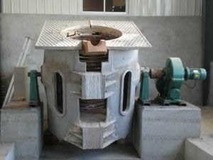
Technical analysis of 5 T/ 4000 KW/ 300 Hz medium frequency induction melting furnace
The 5 ton medium frequency induction melting furnace is a 5 ton series inverter medium frequency coreless induction melting furnace for steel smelting. The program also includes equipment water cooling system and transformers, as well as all equipment quotation andturnkey project prices .
First, the general rules:
The scope of use of this technical solution is limited to the technical requirements of Party A's 5 ton medium frequency induction melting furnace . The complete set of 5 ton electric furnace equipment includes: selection, design, manufacture and factory test of all equipment components in the overall design and supply scope of the equipment. Technical requirements and services such as handover test, packaging, transportation, installation, commissioning, warranty, equipment commissioning, and after-sales service.
Party B is responsible for providing the complete machine qualification certificate, test report, relevant drawings and materials, instructions for use, equipment manufacturer certificate and instructions for use.
This technical solution shall be approved by Party A and signed a technical agreement, which is one of the annexes to the contract and has the same legal effect.
After the technical requirements and standards involved in this technical solution, Party A and Party B are responsible for the quality and safety of the products involved after confirming the signature.
Second, equipment performance and characteristics:
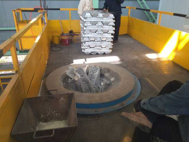
5 tons of medium frequency induction melting iron furnace use: used for melting scrap steel, ductile iron, alloy structural steel, high nickel alloy steel, heat resistant alloy.
The equipment consists of:
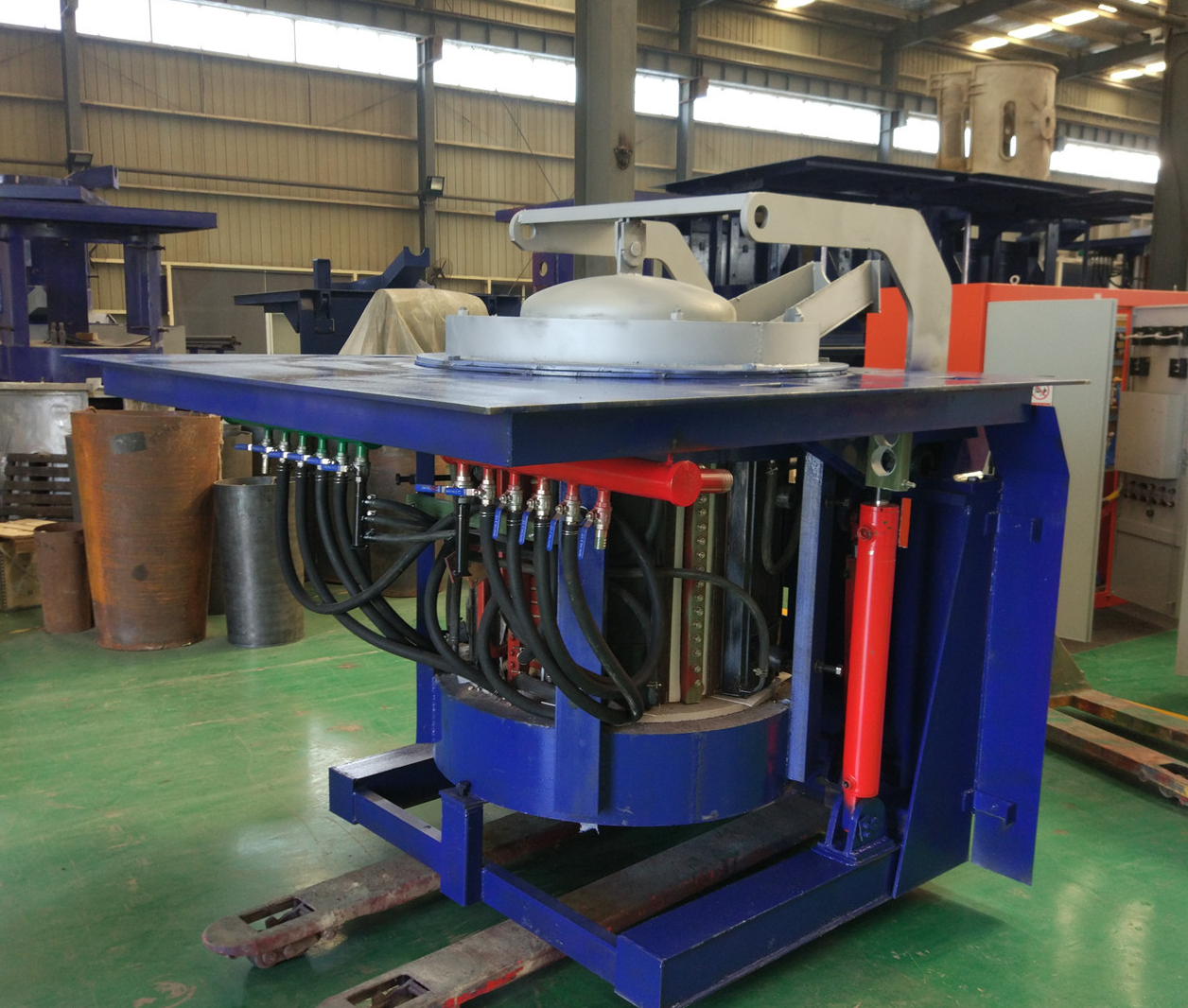
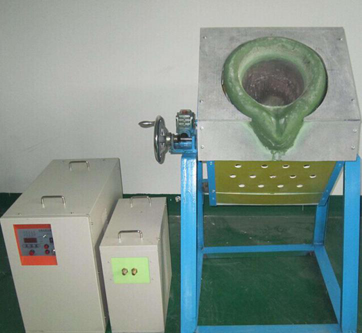
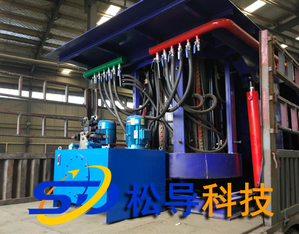
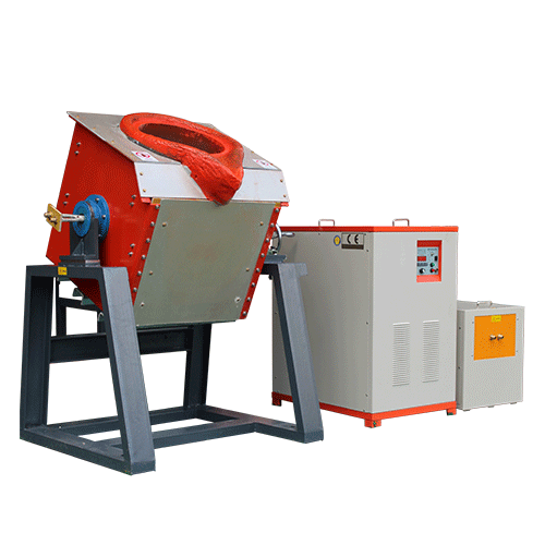
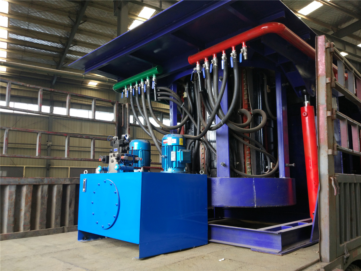
The equipment of this scheme consists of a high voltage switchgear, a rectifier transformer, a 12- pulse intermediate frequency power supply, and two 5 ton furnace bodies (with and without a furnace cover). And hydraulic operation mode), one hydraulic device (one for dual pump hydraulic system, four for hydraulic tilting cylinder, one for furnace lining), one tilting table, water distributor, water cooling device , one The set of intermediate frequency power supplies respectively supply power to the two electric furnaces, and the two furnaces can be simultaneously smelted, or one medium frequency induction melting furnace can be smelted, and the other medium frequency induction melting furnace can control the required temperature for casting or heat preservation. (Weighing 5 tons of medium frequency induction melting furnace) can be set by users according to their needs.
5 tons medium frequency induction melting iron furnace : It is the most energy-saving medium frequency induction melting iron furnace developed by our company. It is the mainstream mainstream medium frequency induction melting furnace in the future. The intermediate frequency power supply adopts the thyristor full-controlled rectifier circuit. The voltage regulation and frequency modulation power adjustment is different from other series intermediate frequency induction melting iron furnaces. The DC voltage is first adjusted, and the inverter frequency is adjusted. The protection is the pull-in inverter fast pull negative pressure protection. It is the biggest advantage of our company's series medium frequency induction melting furnace. Pull inverter protection can effectively protect thyristor overcurrent damage.
The equipment has protection systems such as overvoltage, overcurrent, lining, water temperature, water pressure, short circuit, grounding, etc., and has indications such as fault and temperature.
Features: 5 tons of medium frequency induction melting furnace energy saving effect is remarkable
The rectification adopts the 12-pulse thyristor intermediate frequency power supply, and does not contain the 5th and 7th harmonic components. According to the harmonic analysis, the harmonic influence generated by the 12-pulse rectified power supply is much smaller than the 6-pulse ordinary KGPS intermediate frequency power supply . The control system is fully digital and the startup success rate is 100%.
The series inverter uses a half-bridge circuit, the number of main circuit components is relatively reduced, and has a high power factor, so there is higher power.
1. High power factor operating characteristics with a power factor of 0.9 6 . efficient. Constant power output, power output is controlled by constant. During the melting process, when the load and temperature change, the load is always full power output, whicheffectively shortens the melting time. Parallel frequency inverter technology using electric average power factor of 0.85, in series inverter technology power factor 0.96
2. Compared with other circuits, the current of the load circuit is 10-12 times smaller, which can save 3% of running power consumption .
3, no need for large-capacity filter reactors can save 1% power consumption
4. Each induction melting furnace is independently powered by a group of inverters. It is not necessary to install a large current to change the furnace switch to save 1% of power consumption .
5. In series inverter, there is no power concave part in the running power characteristic curve, that is, the power loss part makes the smelting time significantly shortened, which increases the output and saves electricity consumption .
Third , 5 tons of medium frequency induction melting furnace main technical parameters
|
project |
unit |
data |
|
Electric furnace parameters |
T |
5 t |
|
Rated Capacity |
t |
5 |
|
Maximum capacity |
t |
6 |
|
Lining thickness |
Mm |
|
|
Inductive circle |
Mm |
85 0 |
|
Induction loop height |
Mm |
150 0 |
|
Maximum working temperature |
°C |
1800 |
|
Electrical parameters |
|
|
|
Transformer capacity |
KVA |
400 0 |
|
transformer Primary voltage |
KV |
10 |
|
transformer Secondary voltage |
V |
950 |
|
Intermediate frequency power supply rated power |
KW |
4 000kw melting furnace power 30 00kw, holding furnace 10 00kw, power adjustable |
|
Coil voltage |
V |
3000 |
|
Rated operating frequency |
Hz |
300 |
|
Power conversion efficiency |
% |
96 |
|
Start success rate |
% |
100 |
|
Comprehensive parameter |
|
|
|
Equipment power factor |
|
≥0.9 6 |
|
Melting rate (heating to 1800 °C) |
t/h |
8 |
|
Melting power consumption (heating up to 1800 °C) |
KW.h/t |
58 0 |
|
Working noise |
Db |
≤75 |
|
Hydraulic system |
|
|
|
Hydraulic station capacity |
L |
8 00 |
|
Working pressure |
MPa |
15 |
|
Hydraulic medium |
|
Hydraulic oil |
|
Cooling water system |
|
|
|
flow |
M3/h |
120 |
|
Water supply pressure |
MPa |
0.2 to 0.3 |
|
Inlet temperature |
°C |
5~35 |
|
Effluent temperature |
°C |
35~55 |
|
Leakage alarm device |
2 sets |
|
|
price |
960,000 |
|
Fourth , technical standards and equipment operating conditions
This equipment is designed and manufactured to meet the following national standard and Ministry standard technical standards.
1, GBl0067.3-88 basic technical conditions of electric heating equipment - induction electric heating equipment
2, GBl0063.3-88 test method of electric heating equipment - coreless induction furnace
3, GB5959.3--88 safety of electric heating equipment - for induction and conductive heating equipment
And special requirements for induction melting equipment
4, JB4086--85 IF coreless induction heating electronic control equipment technical conditions
5, JB/T4280-93 medium frequency coreless induction furnace.
6. GB/T14549--93 Power Quality—The performance and technical parameters of the harmonic equipment of the shared power grid meet the specifications of the technical specifications.
Fifth, the normal operating conditions of the equipment as follows.
1. Environment:
a. The altitude does not exceed 1000m.
b. The ambient temperature is between 5 °C and 40 °C.
c. The relative humidity is not more than 90% (at 25 ° C).
d. There are no conductive dust, explosive gases and corrosive gases that can damage metals and insulation.
e. No obvious vibrations and bumps.
2, power supply requirements:
a. The main circuit power supply voltage is 1OKV 50Hz, the fluctuation is not more than 5%, and the three-phase unbalance is not more than 5%.
b. The control system supply voltage is 220V, and the fluctuation is no more than 5%.
c. The main circuit and control system supply voltage must be sinusoidal, and the waveform distortion is not more than 10%.
3, external circulation cooling water requirements (when using wind-water cooling device without this requirement):
a. Total hardness < 60mg equivalent / L
b. Soluble solids <300mg/L
c. PH value 7-8.5
d. Suspended solids
e. Conductivity <500ps/cm
f. Inlet water temperature ≤35°C
Six , 5 tons of medium frequency induction melting furnace electrical part of the technical description
1, high voltage switch cabinet (user optional ):
The high voltage switchgear is installed in front of the rectifier transformer to protect the transformer.
KYN28-12 hand truck type high voltage switchgear:
This switchgear is equipped with a vacuum circuit breaker, which is suitable for cutting capacitor banks and electric furnace transformers.
Such as frequent operations. The circuit breaker of this structure is a hand-car type structure, and the switch cabinet can be pulled out, and the maintenance is very convenient.
2, power rectifier transformer (user optional ):
The power rectifier transformer is used to reduce the 1OKV high voltage of the power grid to a voltage suitable for the intermediate frequency power supply. The IF equipment uses a dedicated rectifier transformer, and the oil is immersed in the self-cooling mode.
2.1, 12 pulse rectifier transformer:
This kind of rectifier transformer generally adopts Y/d11, Y0 connection group mode, and the secondary output is two groups, one set of outputs is Y type connection, and the other set of output is d11 type connection, so the phase of the two sets of output will be The difference between each other is 30°, that is, a rectification method of 12 pulses is formed. Compared with the six-pulse rectification, this rectification method can effectively suppress the 5th and 7th harmonics, and can reduce the interference of the harmonic components to the power grid. Therefore, in the large electric furnace (more than 2500KW), the rectifier transformer is used.
2.3, the parameters of the rectifier transformer:
|
Electric furnace capacity (t) |
IF power (KW) |
Transformer capacity (KVA) |
Voltage combination |
Connection group label
|
Impedance voltage (%) |
|
|
Primary side (KV) |
Secondary side (V) |
|||||
|
5 |
4 000 |
4 000 |
10 |
95 0 |
Y/d11, Y0 |
6-8 |
Note: There should be no load voltage regulator on the high voltage side of the transformer, the voltage is -10%, -5%, 0,
+5%, +10% five-speed adjustment.
3, IF power supply
3.1, the circuit uses 12 pulse wave rectification mode, the incoming line voltage is 95 0V. The inverter uses a half bridge inverter. The intermediate frequency power supply of this kind of line is suitable for a larger capacity electric furnace with a power of 1500 KW to 1000 0 KW . 3. 2 IF power structure features:
3. 2. The rectifying part of the thyristor uses the latest stacked radiator
This type of installation makes the thyristor disassembly and assembly more convenient and scientific. When replacing the thyristor, you can replace any thyristor component in the component by loosening a captive bolt. The radiator assembly has a scale for reference when tightening, which ensures the correct pressing force between the thyristor and the heat sink. Moreover, this mounting method substantially reduces the volume of the thyristor assembly and increases the operating space within the electrical cabinet.
3.2 .2 large capacity DC smoothing capacitor
The filter capacitor is very important for the solid power supply. It can make the output voltage of the rectifier smooth and stable, provide a stable and smooth voltage for the inverter, and make the inverter waveform stable and reliable.
3.2 .3 inverter circuit with large capacity and fast freewheeling diode SCR
In order to ensure reliable operation and reliable freewheeling of the inverter, the inverter thyristor and freewheeling diode adopt large-capacity KK thyristor and fast diode.
4, leakage furnace protection and grounding alarm trip function
The control system has a dedicated lining thickness detector. The working principle is to judge the integrity of the lining according to the magnitude of the leakage current between the induction coil and the charge. Because when the furnace lining becomes thin, the leakage current must increase.
The alarm current of the lining thickness detector can be adjusted. The appropriate alarm current must be adjusted step by step according to different sizes of electric furnace and different lining materials. The lining thickness detector cannot be 100% accurate, it can only be used as a reference for judging the thickness of the lining. The lining thickness detector is directly connected between the side electrode and the bottom electrode.
5, compensation capacitor bank
The characteristic of the series-type intermediate frequency power supply is that the tank current is the same as the output current of the intermediate frequency power supply, and the voltage of the tank circuit is Q times the output voltage of the intermediate frequency power supply. Since the current of the tank is relatively small, the compensation capacitor is installed in the intermediate frequency power cabinet. Simply connect the furnace body with a water-cooled cable. The workload at the installation site is greatly reduced.
6 , electric furnace part
The electric furnace part includes an electric furnace body, a water-cooled cable, a refractory cement, a lining quick-release device, and a main circuit copper platoon.
6. 1. Furnace body
The furnace body is composed of an induction coil, a yoke, a hob, a tilting cylinder and a furnace cover.
6.1.1 Induction coil
The induction coil is made of 99.9% rectangular copper tube. The induction coil is made of bandaged mica tape and immersion insulation paint. The exterior is coated with a layer of gray insulating varnish. The insulation layer has a withstand voltage greater than 5000V. The induction coil is fixed by a series of bolts and insulating stays welded to its outer circumference. After the coil is fixed, the pitch error of the coil is not more than 2 mm.
A stainless steel water-cooling ring is arranged on the upper part and the lower part of the induction coil, and the purpose is to make the lining material uniformly heated in the axial direction and prolong the service life of the lining. At the water outlet of the induction coil, several water temperature probes are installed according to the water path. When the water temperature of a certain road is blocked, the alarm can be immediately issued, and the intermediate frequency power supply can be automatically stopped.
6.1.2 , yoke
The yoke is made of a high permeability cold rolled silicon steel sheet. The thickness of the silicon steel sheet is 0.3 mm. The yoke adopts a profiling structure, and the arc of the inner arc surface is the same as the outer arc of the induction coil, so that the yoke can be evenly distributed on the outer side of the induction coil, thereby maximally restraining the magnetic field radiated outward from the coil and reducing the external magnetic circuit. Magnetoresistance.
The yoke is clamped by stainless steel plates and stainless steel clamps on both sides and fixed by welding. A cooling water pipe is welded to the stainless steel plate on both sides for cooling the yoke. The cooling water pipe can withstand 0.45Mpa water pressure and no leakage within 15min.
After the yoke is assembled, the bending degree is not more than 4 mm, and the deviation between the theoretical center line and the actual center line is not more than 3 mm.
A PTFE sheet and an asbestos rubber sheet are interposed between the yoke and the coil. The PTFE sheet has high dielectric strength and high temperature resistance, and the asbestos rubber sheet has high heat resistance. This ensures insulation and heat resistance between the yoke and the coil.
Each yoke is fixed by a screw rod fixed on the furnace shell, and a uniform top force is formed in one circumference of the coil, so that the yoke is fixed and the coil is fixed, and the coil is not generated during the melting and discharging process. mobile.
6.1.3 , hob
The hob is divided into two parts.
6.1.3 , 1 , movable hob
The movable hob is used to mount the induction coil and the yoke. It is welded from profiled steel and steel plate and has a frame structure for easy maintenance. The operating platform at the top of the movable hob is made of thick steel plate to improve the strength and load-bearing capacity of the hob.
6.1.3 , 2 , fixed hob
The fixed hob is mounted on the foundation for carrying the movable hob. The upper part of the fixed hob is connected by the tilting shaft and the movable hob. Under the pushing of the tilting cylinder, the movable hob can be tilted forward by 95 degrees.
The hob section is designed with a large safety factor. Ensure that the hob has sufficient rigidity to run smoothly when carrying the maximum load.
6. 1.4, furnace cover
A furnace cover is mounted on the movable hob. The operation of the furnace cover is either manual or hydraulic.
6. 1.4.1, manual furnace cover
The manual furnace cover is mounted on the rotating shaft on the side of the upper end of the furnace body, and the furnace cover can be opened and closed by pulling up and down the handle. When feeding or when the furnace cover is not required, the furnace cover can be rotated to the side position of the upper part of the furnace body.
6. 1.4.2, hydraulically driven furnace cover
The hydraulically driven furnace cover is mounted on the rotating shaft on the side of the upper end of the furnace body, and the opening and rotating action of the furnace cover is realized by the action of the upper and lower oil cylinders and the rotating oil cylinder. Operate through the operation switch on the console. When feeding or when the furnace cover is not required, the furnace cover can be rotated to the side position of the upper part of the furnace body.
7, water-cooled cable
The connector of the water-cooled cable has a detachable structure and can be easily disassembled. The inside is connected to the copper strand by soldering. In this way, the connection is firm and the contact resistance is small.
The outer casing of the water-cooled cable is a rubber tube. This hose is not easy to burn and has good strength. It can withstand 0.45Mpa water pressure without leaking or breaking.
The rubber tube will age after long-term use and will be replaced at this time. This detachable structure does not need to damage the internal copper strands, and it is only necessary to disassemble the bolts on the joints to easily replace the outer rubber hoses.
The inside of the joint is sealed with a tapered cone and is electrically conductive. When the joint bolt is tightened, it naturally acts as both conductive and sealed.
8, refractory clay
Refractory clay is a highly insulating and insulating material that is applied to the inside and outside of the induction coil and has the following effects:
(1) Make the induction coil as a whole, reducing vibration and noise during operation.
(2) Protect the induction coil when the charge leaks.
(3) Conducive to the launch of the lining.
9 , furnace lining rapid launch device
The lining quick-release device is used to quickly remove the old lining. It includes a push block, a push cylinder and an operating mechanism.
The jacking block is mounted under the lining and is connected to the jacking cylinder through a pushing hole at the bottom of the furnace body. When the old furnace lining needs to be introduced, the electric furnace is tilted to 90 degrees, and the thrust pin is fixed by the fixing pin and the connecting flange at the bottom of the furnace body, and the old furnace lining can be pushed out by operating the manual valve to pressurize the oil cylinder.
Seven , hydraulic system
Includes hydraulic pumping station and tilting station.
The hydraulic pumping station is used to power the tilting cylinder, the lid drive cylinder, and the lining to push the cylinder. The rated working pressure of the pumping station is 11Mpa. The hydraulic medium is hydraulic oil.
The tilting table is used to control the tilting of the furnace body, to fall back, the switch of the furnace cover and the lining of the furnace. It is operated by a manual valve with smooth movement and no impact. All hydraulic components are made of domestic quality products.
Eight , water cooling device (user optional )
(Optional) According to your own situation, you can also purchase or build a cooling pool to save the closed circulation cooling tower .
The water tank can be built at the production site, and the water circulation can be used to cool the 5 ton medium frequency induction melting furnace by water pump . A complete set of combined cooling equipment can also be used . Power recommended F bt - 1 0 0 closed loop cooling tower, an electric furnace using F bt - 15 0 Closed loop cooling tower, can save a lot of space and production area.
Nine, the main components supporting manufacturers (for famous manufacturers)
|
1. Power cabinet: |
(1) Main breaker |
Shanghai People's Electric Appliance Factory or Delixi DW Series |
|
|
(2) Rectifier thyristor |
Hubei Xiangfan Power Electronics Group Co., Ltd. |
|
|
(3) Inverter thyristor |
Hubei Xiangfan Power Electronics Group Co., Ltd. |
|
|
(4) Main control board |
Luoyang Wancong Power Equipment Co., Ltd. |
|
|
(5) buttons, indicators, etc. |
Shanghai Electric Appliance Factory |
|
|
(6) Protecting the thyristor's resistance and capacitance |
794 factory and 795 factory |
|
|
Copper material ⑺ |
|
|
2.Electric heating capacitor |
|
Luo yang songdao induction heating technology Co.,LTD |
|
3. Stove |
(1) Induction coil copper tube |
Luoyang Copper or Zhejiang Shangyu Copper Material Factory |
|
|
(2) Silicon steel sheet |
Wuhan Iron and Steel Company |
|
|
(3) Hydraulic cylinder |
Shanxi Yuci Group |
|
4.Hydraulic system |
(1) Hydraulic components |
Shanxi Yuci Group Hydraulic Factory |
|
|
(2) oil pump |
Shanxi Yuci Group Hydraulic Factory |
|
|
(3) Motor |
Xi'an or Kaifeng Motor Factory |
|
5. Transformer |
|
Tongniu Transformer Factory (optional) |
|
6.Waterway system |
( 1) FBT closed cooling tower |
Ark or Ruiwo (optional) |
|
|
( 2) Water pipes and hoses |
Kaifeng Rubber Factory or Jiaozuo Rubber Factory |
|
|
(3) Other valves and piping |
Luoyang City Building Materials Market |
X. Scope of supply:
|
Serial number |
name |
Specification model |
unit |
Quantity |
Remarks |
|
1 |
Rectifier transformer |
12-pulse double rectifier 4000 KVA |
set |
1 |
Optional |
|
2 |
IF power cabinet (including low voltage switch cabinet) |
KGPS - 4000 /0.5 |
set |
1 |
|
|
3 |
Compensation capacitor cabinet |
|
set |
2 |
|
|
4 |
Furnace body |
GW 5 - 4 000 |
set |
2 |
|
|
5 |
Hydraulic power station |
|
set |
1 |
|
|
6 |
Incubator console |
|
station |
2 |
|
|
7 |
Furnace lining device |
|
set |
1 |
|
|
8 |
Leakage alarm device |
|
set |
2 |
|
|
9 |
Furnace building tool |
|
set |
1 |
|
|
10 |
Water cooled cable |
|
set |
2 |
|
|
11 |
Model |
|
only |
2 |
|
|
12 |
Connecting cable and copper bar |
Power cabinet to capacitor cabinet |
set |
2 |
|
|
13 |
Water dispenser |
|
set |
2 |
|
|
14 |
Water cooling device |
F bt - 1 00 closed cooling tower F bt - 1 50 0 circulating cooling tower |
set |
Each 1 |
Optional |
|
15 |
Domestic transportation (to the use site) |
|
set |
1 |
Optional |

