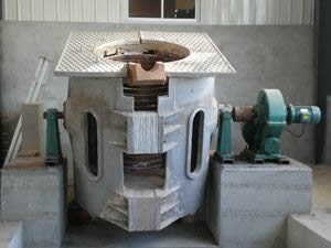
Main technical indicators of busbar trunking of intermediate frequency induction melting furnace
1) Busbar three-phase six-wire system, the number of wires is: L1 , L2 , L3 , L11 , L12 , L13 .
2) Type: copper conductor busway
3) Rated operating voltage: 1000V or less.
4) rated insulation voltage: below 1000V
5) Rated operating current: 3000A
6) Rated frequency: 50~60HZ .
7) Insulation resistance: the insulation resistance of each unit busway is not less than 50 megohms (the national standard is not less than 20 megohms)
8) Dielectric performance: The power frequency withstand voltage of each unit busway is 4500V , the busbar system power frequency withstand voltage is 3750V , and there is no breakdown flashover for 1min .
9) Temperature rise: When the busbar system works normally at rated current, the temperature rise is not higher than: 60K at the joint , 30K at the outer casing , and 40K at the inner tank .
10) Heat resistance level: Class C.
11) Protection level: IP54 .
12) The busbar conductor T2 is electrolytically copper-bonded into a TMY electrician copper row, and the purity of the copper row is 99.95% or more (providing inspection report).
13) Three-phase five-wire busbar A , B , C , N phase cross-sectional area to ensure that all parts are consistent, the busbar should also have a separate PE conductor, the busbar surface is tinned, the independent PE phase is the phase line of 1/2 busbar The surface is smooth and flat.
14) The busway housing is made of cold-rolled sheet and has sufficient mechanical strength. The span is 3 meters or 6 meters. There should be no deflection between the support points. Each joint unit is equipped with a joint assembly.
15) The busway housing should be completely sealed. A special fire barrier is designed when the busway is through the wall and through the floor to avoid the fire spread during the fire. The busway spacer is made of 4220 arc resistant powder.
16) The busway is equipped with a dedicated transformer connection system and a power distribution cabinet connection system. The connection is time-saving, convenient, safe and reliable. It is connected with the transformer to configure a soft connection to prevent the vibration of the transformer from affecting the entire power distribution system. The connection to the power distribution cabinet is connected by a connecting copper bar and a cabinet top box.
17) The busbar joint must be designed to meet the linear expansion of the trunk due to thermal expansion without reducing the mechanical strength, electrical connectivity, current carrying capacity, and short-circuit flow of the busbar. When the straight section of the busway is more than 80 meters in the case of no elbow or tee , the expansion joint busbar should be considered.
18) The busbar slot is connected by a fastening terminal, which is quick and easy to replace and easy to maintain. Remove any busbar without affecting adjacent units.
19) According to the drawings and design instructions, the horizontal installation is generally vertical vertical installation.
20) The busbar connection is double-sidedly overlapped to reduce contact resistance and avoid heat generation at the joint. The material of the connector box pin and the bus bar connector is tin plated with copper.
21) The bidder shall, in accordance with the national standards, increase the functional unit such as the expansion joint to ensure the use and safety at a certain position.
22) The number of T -joints, the number of variable capacity sections, and the specifications and quantity of the starting line box (with starting busbar) of each substation and the interface requirements of the power distribution cabinet of the substation are strictly in accordance with the material list.
twenty three) Other technical requirements are strictly in accordance with the design drawings and should be in accordance with current national standards.

