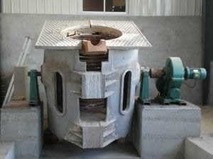
Nitrogen protection rotary sintering furnace design
First, the use of equipment:
This equipment is mainly used for the roasting of powder materials such as lithium iron phosphate.
Second, the process brief
Through the rotary motion of the drum with a certain angle of inclination, the powdery material is driven to make a reverse spiral motion in the drum, and the various temperature zones set by the heating chamber of the furnace body are used to complete the product under the action of the furnace atmosphere. Sintering process.
Third, the main technical parameters:
1 , Design temperature: 800 °C;
2 , Operating temperature: 400 ~ 700 °C;
3 , Furnace tube size: φ 7 0 0 × 1 5500 mm ;
4 , Heating section length: 10500 mm ;
5 , Heating method: the resistance wire rod is arranged horizontally, and the upper and lower parts are heated;
6 , Heating element: resistance wire rod ;
7 , Temperature control mode: Solid state relay zero-crossing trigger, intelligent instrument temperature control;
8 , Number of temperature control groups: 11 groups;
9 , Temperature control accuracy: ≤ ± 2 °C;
10 , Design power: 150Kw ; insulation power is about 80Kw ;
11 , Drum velocity: 0.1 ~ 1 r / min, stepless adjustable continuously;
12 , Inclination angle of the furnace body: 0 ~ 2 ° continuous stepless adjustable;
13 , Process atmosphere: high purity nitrogen;
14 , Material advance speed: 680 mm / hour;
15 , Production capacity: 65K g / h (feed amount, calculated according to raw material bulk density 0.8 g/cm 3 , sintering time 910 minutes , no cooling time);
16 , Filling rate of material in the cylinder: 30 %;
17 , Feed bin effective volume: 700 liters;
18 , Mode of operation: Fully automatic continuous feeding and discharging;
19, The height of the discharge port: 1000 mm ;
20 , Discharge temperature: no more than 40 °C;
21, Oxygen content in the furnace: 10 ppm + gas source oxygen content + raw material oxygen content;
22 , Sample gas collection method: Pumped oxygen analyzer automatically samples.
Fourth, the device structure profile:
The equipment is mainly composed of a furnace body, a feed conveying device, a drum transmission device, a sealing device at both ends of the drum, a spray water cooling device, a spiral discharge cooling device, a gas path portion, and an electric appliance portion.
1. Furnace body: The furnace body is mainly composed of furnace lining, drum and hob.
The whole lining is made of lightweight material structure, and the thermal insulation materials on both sides of the furnace are aluminum silicate refractory fiber products with light weight and excellent thermal insulation performance. In order to ensure the strength of the bottom of the furnace, the bottom of the furnace is made of lightweight refractory insulation material and light diatomaceous earth with good insulation performance and lightweight high-alumina brick. In order to facilitate the assembly of the drum, the roof is made in a detachable form. In order to reduce the weight of the furnace roof, enhance the heat preservation effect and facilitate the operation, the top of the furnace is made of aluminum silicate fiber hard board and aluminum silicate fiber felt. The whole lining is light-weight material, which has the advantages of good thermal insulation performance, small heat storage and fast heating speed.
The drum is placed in the middle of the furnace and is made of SUS310S ( 0Cr25Ni20 Si 2 ). Roller diameter 0.7 meters, a total length of 15.5 m, wherein the heating zone length of 10.5 m. The rollers are supported by the rollers disposed at the two ends of the furnace body, and two rollers are provided in front and rear, and the rollers can be adjusted in the radial direction of the rollers to ensure that the rollers are concentric with the furnace. The drum is provided with a certain inclination angle. After the material enters the drum, during the rotation of the drum, the material passes through the furnace at a certain speed to complete the heating process.
A condensate water retaining ring is arranged at a temperature greater than 100 ° C of the feed end of the drum , and the condensed water is blocked outside the material portion of the drum, and is discharged into the condensed water collecting chamber by the nozzle end of the drum. The feed port of the screw feeder opens into the inside of the heating end of the drum retaining ring. Reliably prevent condensate from flowing back and mixing with the material to cause adhesion to the wall.
The discharge end of the drum is provided with an outlet fixing cover for installing the intake pipe and the inlet sealing ring. A spiral discharge cooling device is arranged at the lower end of the outlet fixed cover. The inlet end of the drum is provided with an inlet fixed cover for installing the outlet pipe and the inlet sealing ring. The exhaust gas generated by the material in the furnace and the process gas introduced therein are discharged from the exhaust port. The exhaust port can be adjusted in size to ensure the pressure in the furnace. A condensed water collecting chamber is disposed at a lower portion of the inlet fixed cover, and the condensed water is discharged through the drain pipe.
On the inlet fixed cover, there are inlet and discharge upper and lower level level switches to control the automatic operation and stop of the incoming and outgoing materials as required. An oxygen content analyzer sampling port is respectively arranged on the inlet fixed cover and the outlet fixed cover, and the oxygen content analyzer adopts a zirconia oxygen analyzer equipped with an air pump inside, in order to prevent the influence of dust on the accuracy of the oxygen analyzer, at the sampling port A filter device convenient for washing and unloading is installed in the pipeline of the oxygen analyzer.
A drum tilt adjustment device is arranged at the front of the hob to adjust the appropriate inclination according to the process requirement, and the adjustment range is 0. - — 2 °.
In order to ensure uniform heating of the material and sufficient contact between the material and the atmosphere in the furnace, a fry plate is welded in the drum. In order to eliminate the thermal expansion of the drum, the feed end of the drum is fixed so that the direction of expansion proceeds in the direction of the discharge port. In order to prevent the material from sticking to the inner wall of the drum, a hammer is provided at both ends of the heating section of the drum. In order to prevent damage to the drum and the product due to accidental power failure, an accidental power-off hand crank mechanism is provided in the drum drive device.
The hob is welded with high-quality steel and steel plates to support and connect the various components of the whole equipment, and the exterior is coated with anti-rust paint.
2. Screw feed conveyor:
The spiral feed conveying device is composed of a feeding hopper, a spiral quantitative feeding device, a sprocket, a speed regulating motor and the like. The material enters the quantitative feeding device through the feeding hopper. During the rotation of the screw shaft, the material enters the drum according to a certain flow rate. The feeding amount is 0~70 Kg/h continuously and infinitely adjustable, and the frequency converter frequency display can be converted into actual Feed amount. In order to eliminate the air trapped in the feed material, a nitrogen gas curtain and an intake pipe are provided at the lower portion of the feed funnel and at the front end of the screw feeder. The feeding hopper is made of stainless steel and has upper and lower limit level switches on the upper and lower ends of the feeding hopper to control the feeding device of the front end of the equipment to feed the feeding hopper of the equipment. When the material level in the feeding hopper reaches the upper limit, the feeding stops; when the material level in the feeding hopper reaches the lower limit, the feeding starts, so as to ensure that a part of the material is always sealed in the feeding hopper . The material level switch can also output the feeding alarm signal, which is used for the automatic feeding line of the supporting materials at the demand side, but for the manual feeding.
3 , drum drive:
The drum transmission part is arranged at the feeding end of the furnace body, and is composed of a sprocket, a speed reducer, a speed regulating motor, a gear spoke and the like. To ensure the transmission velocity of the material, in order to meet the requirements of the sintering process, the drum speed at 0.1 to 1 revolution / minute continuous stepless adjustable.
4 , the sealing device at both ends of the drum:
In order to ensure the reliable sealing of the drum, prevent the outside air from entering the furnace and the exhaust gas generated by the reaction overflowing and polluting the environment, at both ends of the drum, a double graphite sealing ring is used as a sealing element, and the graphite is passed through the grinding action between the moving and static graphite rings to make the graphite A good sealing joint is formed between the rings. At the same time, a sealed pressure gas ring is arranged on the static graphite ring, and the atmosphere inside and outside the furnace is effectively insulated by the high-purity nitrogen pressure in the gas ring. In order to ensure a certain sealing joint surface pressing force and eliminate the thermal expansion of the drum, an elastic expansion compensating ring is arranged outside the fixed end graphite ring sealing member, and the outer edge of the expansion compensating ring is equipped with an adjustable spring to adjust the appropriate pressure according to the expansion condition of the drum. Tight force.
5 , spray water cooling device:
A spray water cooling device is provided at the end of the heating section for preliminary cooling of the sintered product. At the same time, the spray water cooling device also plays a role in reducing the temperature of the furnace tube in the outlet section and improving the reliability and service life of the outlet sealing portion.
6, helical feed cooling means: the cooling means and composed of helical feed means.
The cooling device is composed of a water cooling jacket and a pipeline. The water-cooled sleeve is made of stainless steel, with multiple sets of guide plates inside, which are reverse-cooled. The material spreads out during the movement and slides around the cooling sleeve. It has the characteristics of high cooling efficiency, and the flow of the cooling water is adjusted. And valve) to adjust the cooling rate to further ensure the product outlet temperature.
The screw discharge device is mainly composed of a screw, a motor, a sprocket, a chain, a discharge bin, and the like. After the product is fired, it falls into the discharge bin, and the discharge screw moves under the driving of the motor and the speed reduction mechanism, and discharges outward. A nitrogen gas curtain is provided at the outlet of the spiral discharge device to prevent air from entering the furnace through the discharge spiral gap.
7, the gas path part:
The gas path portion is composed of an air intake portion and an air outlet portion.
The intake portion is disposed at the discharge end of the kiln, and the intake air is introduced into the furnace by the outlet fixed cover. A flow meter and a regulating valve are arranged in the intake pipeline , and the intake air amount is 0 to 20 N m 3 /h , which is infinitely adjustable.
The outlet part is arranged at the feeding end of the kiln, and the outlet gas is arranged above the outlet fixed cover, and is equipped with a flow regulating valve, and the atmospheric pressure of the furnace is adjusted by adjusting the size of the outlet port.
8 , electrical control part:
The electrical control part is composed of an electronic control part, a temperature control part and the like. Each part is installed in a uniform control cabinet. The installation in the control cabinet is neat and orderly, and the arrangement is smooth. The power line and the control line are isolated and reliable without interference. All components have corresponding Chinese signs or logos, all wirings have corresponding line numbers, easy to operate and maintain. The control cabinet has an independent lighting system and a heat dissipation channel. The lower side of the control cabinet is provided with an air inlet with a filter net, and the upper part is provided with an exhaust fan, and the airflow in the cabinet is smooth, thereby ensuring the use of the device.
Electronic control part: The whole system is distributed by air switch. It is equipped with total power air switch and air switch of each temperature difference. The air switch capacity is reasonably selected according to the power of each temperature zone. Each temperature zone is controlled by independent air switch. All electrical components of the electronic control part are imported from Japan Fuji.
Temperature control part: The temperature control part includes temperature control instrument, thyristor, air switch, contactor, etc. The temperature control instruments all adopt imported intelligent instrument. The instrument has PID self-tuning function. The thermocouple indexing number can be set arbitrarily, and the optimal PID value can be automatically tracked and set . The temperature control instrument also has temperature compensation function, which can make the furnace The temperature is consistent with the set temperature display. The temperature control instrument also has an audible and visual alarm function such as over temperature and break.
V. Other:
1, During the manufacturing process of the product, the demand side can monitor the progress and production quality of the equipment according to the schedule.
2, The material for the lining and the drum is supplied to the purchaser and approved by the purchaser.
3, The supplier provides a list of consumables and drawings to facilitate future maintenance by the purchaser.
4, The supplier is responsible for the installation and commissioning of the furnace and provides training and guidance to the operator of the demand side.
5, The power supply connection control cabinet of the equipment to the furnace body is responsible for the supplier, and the front part of the control cabinet is the responsibility of the purchaser.

