Loading rack
The loading gantry is to stack the steel pipes to be heated. The gantry is welded with 16mm thick steel plate and 20 hot-rolled I-beams. The width of the table is 200 mm, the table top is set at 3°, and 8 φ325mm steel pipes can be placed. The columns are bolted. When working, the crane can hang the whole bundle on the gantry, the bundle device feeds, the bundle device is driven by the oil cylinder, the drive device is placed in the middle of the gantry as much as possible, and 7 feeders are installed. One by one automatically rolls to the end of the gantry. The end has a feeding positioning seat. Due to the large difference in the diameter of the steel pipe, the material positioning seat can be adjusted according to the diameter of the steel pipe.
Feed translation mechanism
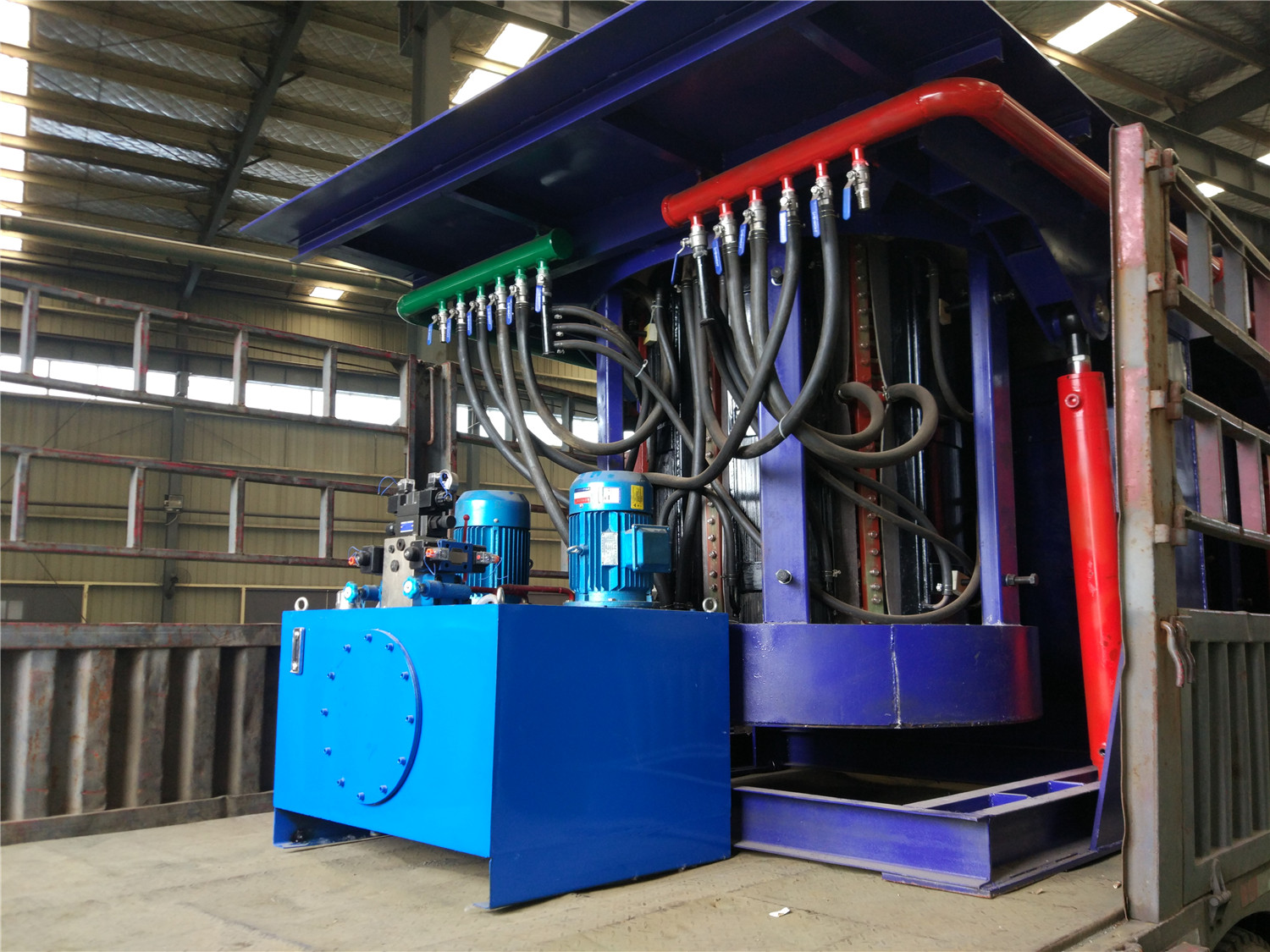
The feed translation mechanism hydraulic drive adopts synchronous valve. There are 6 sets of feeding mechanism and 6 sets of cylinder diameter ф50 and 250mm metallurgical cylinder. Two sets of translation cylinders, diameter φ80, stroke 900mm. The translation is in place, which is exactly the center of the double roller. There are 4 wheel sets under each set of feeding mechanism. The lower support of the wheel set is two 15# light rails, which are accurate, labor-saving, practical and reliable.
Double roller drive
Double roller drive. By adjusting the angle of the double rollers, both the speed of the steel tube rotation and the speed of advancement can be achieved. The double roller transmission adopts a reducer and a frequency conversion speed regulating device to ensure the forward speed requirements of steel pipes of different diameters. There are 38 sets of double idler rollers, the distance between the rollers is 1200mm, the center distance between the two wheels is 460mm, the diameter of the roller is φ450mm, and the steel pipe is φ133mm to φ325mm. One set of rollers is the power wheel and the other set is the support. Passive wheel, considering that the heating furnace has a certain installation position, the power wheel is designed with a set of 1:1 sprocket chain transmissions, aiming to move the center distance of the transmission connection outward by 350mm. All the rollers rotating shafts are provided with water cooling devices, and the roller supports are bearings. In order to ensure the consistent and balanced transmission speed of the workpiece, 38 power inverter motors are used for power. Motor speed control, with frequency converter, φ325 roller speed range: 10-35 rev / min, forward speed 650-2000mm / min, frequency converter speed range: 15-60HZ. The roller is placed at an angle of 5° to the center. The angle can be adjusted to a maximum of 11° and the minimum can be adjusted to 2°. The adjustment of the roller angle is controlled by the motor to drive the turbine vortex. The whole double roller transmission device is installed on the inclined table surface of the climbing slope of 0.5% from the feeding end to the discharging end, so that the residual water inside the steel pipe can be smoothly discharged after quenching.
By controlling the speed of the feeding idler, the heat-treating idler and the discharging idler, the head and tail of the steel pipe are connected into and out of each heating furnace until the pipe body of one steel pipe leaves all the heating furnace bodies and is cooled. The steel pipe that is connected to the head and tail is automatically separated before the bed.
Discharge translation mechanism
The lifting and lowering mechanism of the discharging adopts a lever type. In order to ensure the straightness of the heating steel pipe, the discharging lifting and lowering device has a total of 11 groups of feeding mechanisms, and is combined into one. 11 groups of feeding mechanism can hold and lower the material at the same time, the stroke is 165mm. Synchronization of the heated steel pipe is ensured. The structure adopts the lever action, the lifting cylinder adopts 3 sets of metallurgical cylinders φ90×200, the translation cylinder adopts 2 sets of φ80×1250, the stroke is 1250mm, and the stroke control is installed with the proximity switch and can be adjusted. When the 11 sets of feeding mechanism simultaneously lifted the steel pipe up to 165 mm, the material was displaced from the fixed position to the highest position (165 mm), and the center position of the material was displaced by 6 mm.

