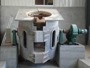
2019 the most complete intermediate frequency furnace commonly used parameter calculation method
Many people are asking how to calculate frequency furnace power, frequency, how to count, incoming and outgoing to choose more than rough and so on, which are involved in the calculation of intermediate frequency furnace, electric furnace today small pine guide you summarize finishing 2019 the most comprehensive The intermediate frequency furnace commonly used parameter calculation method, I believe it will help you.
1. Intermediate frequency furnace power calculation method
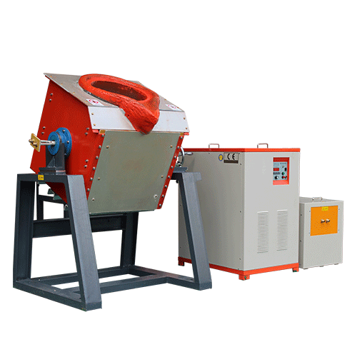
The power of the intermediate frequency furnace is divided into three categories: medium frequency heating furnace power, medium frequency furnace quenching power and medium frequency furnace melting power. The calculation method is as follows:
Medium frequency heating furnace power calculation:
P= ( C × T × G )÷( 0.24 × S ×η)
Intermediate frequency furnace notes:
P = equipment power ( KW )
C= material specific heat ( kcal/kg °C)
G = workpiece weight ( kg )
T = heating temperature, Heating (°C)
t= time ( S )
η = comprehensive thermal efficiency of the equipment, generally 0.5 - 0.7 , and 0.4 of the shaped parts .
For example, a forging factory has a forging blank of Φ 60 × 150 mm , a working cycle of 12 seconds / piece (including auxiliary time), and an initial forging temperature of 1200 °C.
Calculated as follows: P = ( 0.17 × 3.3 × 1200 ) / ( 0.24 × 12 × 0.65 ) = 359.61KW
According to the above calculation, an intermediate frequency induction furnace with a rated power of 400 KW can be configured .
According to the basic principle of electromagnetic induction, the three-phase power frequency alternating current is rectified into a direct current, and then the direct current is converted into an adjustable intermediate frequency current, and a load composed of a capacitor and an induction coil is supplied (the coil and the capacitor can be connected in parallel or in series). A high-density magnetic line is generated in the induction coil, and the metal material contained in the induction coil is cut to generate a large eddy current in the metal material. This eddy current also has some properties of the intermediate frequency current, that is, the free electrons of the metal itself flow in the metal body with resistance to generate heat.
Medium frequency furnace quenching power calculation:
P= ( 1.5 — 2.5 )× S
S= hardening area of the workpiece (square centimeter)
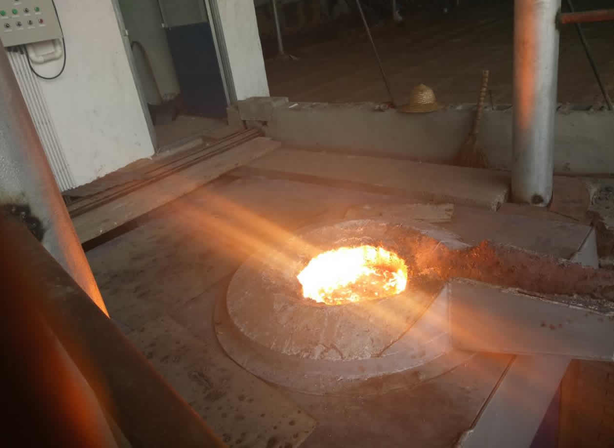
Intermediate frequency furnace smelting power calculation:
P=T/2
T = electric furnace capacity ( T )
2. Intermediate frequency electric furnace frequency calculation
δ = 4500/d2
4500= coefficient
d = workpiece radius
The above is the calculation method of the intermediate frequency furnace power. I believe that you have already learned how to calculate the power of the intermediate frequency furnace. However, in the actual application process, you will find that the intermediate frequency furnace accessories are in good condition, but the power is not going up. Timely adjustment of the power of the intermediate frequency furnace is fine. For the method of adjusting the power of the intermediate frequency furnace, please pay attention to how to adjust the power of the intermediate frequency furnace .
3. Selection of the capacity of the rectifier transformer of the intermediate frequency induction furnace
|
Electric furnace power ( kW ) |
Transformer capacity ( kVA ) |
|
50 |
100 |
|
100 |
160 |
|
200 |
250 |
|
250 |
315 |
|
350 |
400 |
|
500 |
630 |
|
750 |
100 0 |
|
······· |
|
4. Selection of the inlet section of the intermediate frequency furnace
|
Power supply ( kW ) |
Copper core cable ( mm2 ) |
Aluminum core cable ( mm2 ) |
|
50 |
25 |
35 |
|
100 |
50 |
75 |
|
200 |
95 |
150 |
|
250 |
2*70 |
2*120 |
|
350 |
2*95 |
2*185 |
|
500 |
3*95 |
3*185 |
|
750 |
4*95 |
4*185 |
|
1000 |
5*95 |
5*185 |
5. Selection of cross section of output cable of medium frequency electric furnace
|
Output frequency ( KHZ ) Power ( kW ) |
0.5 |
1.0 |
2.5 |
4.0 |
8.0 |
|
50 |
35 |
50/90 |
70 |
95 |
120 |
|
100 |
50 |
70 |
95 |
2*70 |
2*95 |
|
200 |
95 |
2*70 |
2*95 |
4*70 |
4*95 |
|
250 |
2*70 |
2*95 |
3*70 |
5*90 |
5*95 |
|
350 |
2*95 |
3*95 |
4*95 |
5*100 |
5*100 |
|
500 |
3*95 |
4*95 |
5*100 |
5*150 |
5*200 |
|
750 |
4*95 |
5*100 |
5*150 |
5*200 |
( 5*150 ) *3 |
|
1000 |
5*100 |
5*150 |
5*200 |
( 5*150 ) *2 |
( 5*150 ) *4 |
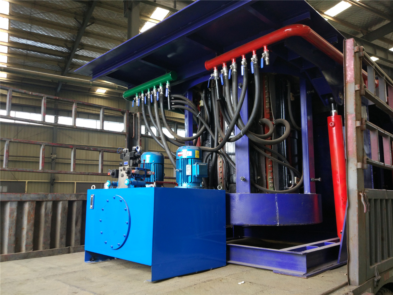
6. Selection of cooling water flow
6.1 Intermediate frequency furnace inlet pressure: 0.15 ~ 0.3Mpa
6.2 cooling water temperature at 5 ~ 30 within the range °, water hardness does not exceed . 8 degrees, turbidity is not greater than 5 , the PH value of 6.5 - . 8 range.
6.3 The following are the requirements of the traffic
|
Power supply ( kW ) |
Heating power supply (including capacitors) |
Diathermy |
Quenching |
Melting |
|
50 |
4 |
4 |
4 |
5 |
|
100 |
4 |
4 |
4 |
8 |
|
200 |
5 |
6 |
6 |
12 |
|
250 |
6 |
7 |
8 |
14 |
|
350 |
7 |
12 |
12 |
18 |
|
500 |
10 |
15 |
15 |
twenty four |
|
750 |
18 |
25 |
25 |
40 |
Note: The full-frequency circulatory cooling system is recommended for medium frequency furnaces.
The above is the calculation method of the commonly used parameters of the intermediate frequency furnace summarized by the pine guide intermediate frequency furnace, so that you can choose the right intermediate frequency furnace to save your cost.

