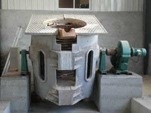
Master furnace worker, do you know the three major alarm systems for induction melting furnaces?
The main alarm protection systems of induction melting furnaces include water cooling alarm system, grounding protection system and overvoltage protection system. This article introduces and analyzes these three protection systems in detail.
1. Water cooling alarm system
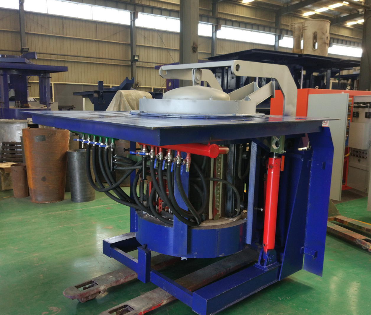
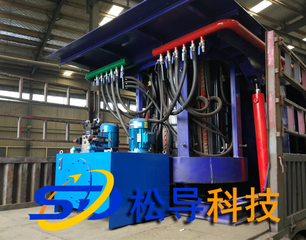
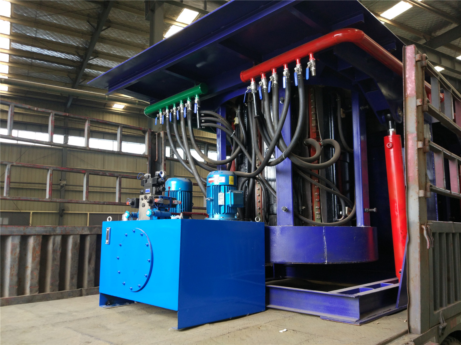
The water cooling system is the most important auxiliary system of the induction melting furnace, which can generally be divided into two parts: the furnace body cooling system and the electrical cabinet cooling system.
The coil of the induction melting furnace body is wound by a square copper tube. Although the resistivity of copper is low, the current passing through is large, and the current in the copper tube shifts to the side of the crucible wall due to the skin effect. , Causing a large amount of heat of the copper pipe (so the insulating paint used on the surface of the copper pipe must have the ability to withstand high temperatures). In order to ensure the insulation of the furnace coil and the safety of the molten pool, sufficient cooling capacity must be guaranteed during the smelting period. And the cooling device must not be shut down before the temperature in the crucible drops to 100°C. The cooling part of the electrical cabinet is mainly used to cool the thyristors, capacitors, inductors and copper bars that will generate a lot of heat during operation. In order to achieve a good cooling effect, it is generally necessary to install an independent cooling tower outdoors. Depending on the power of the equipment, an independent furnace body and electrical cabinet cooling tower are sometimes required.
Common induction melting furnace water cooling alarm systems mainly include:
①The water temperature, pressure and flow meter installed on the water inlet pipe monitor the water inlet parameters of the water cooling system. When the water temperature exceeds the set value, the cooling tower power should be automatically increased. When the temperature exceeds the warning value or the pressure and flow are too low, an alarm and the power supply should be interrupted.
②Temperature sensors that need to be manually reset are installed in series with the outlets of the cooling water pipes of the furnace body and the electric cabinet. During maintenance, the abnormal location can be quickly determined according to the reset button of the temperature sensor.
2. Inverter system grounding alarm
During the operation of the induction melting furnace, the furnace body coil and the capacitor form a high-voltage resonance circuit. Once the ground insulation resistance is low, the high-voltage ground discharge electrode is prone to major safety accidents. In order to ensure the normal operation of the equipment, a ground leakage protection system must be installed.
Common ground leakage protection systems perform two functions:
1) Detect whether there are abnormal paths with low ground resistance among capacitors, furnace coils and busbars;
2) Check whether there is abnormal low resistance between the furnace body coil and the metal charge. This low resistance may be caused by metal charge infiltrating the furnace lining to cause "iron infiltration" or excessive water content in the furnace lining. Conductive debris falling into the furnace lining may also cause the resistance to decrease.
The commonly used alarm system principle is: apply a low-voltage DC power supply to the resonance circuit, and the general induction melting furnace body coils are only slightly insulated. Therefore, the applied DC voltage will be generated between the coil and the molten pool. Some small leakage currents can be detected by milliampere meter. Once the leakage current increases abnormally, it indicates that the resistance of the resonant circuit to ground decreases abnormally. The smelting furnace that uses ground leakage protection generally uses stainless steel wire at the bottom of the furnace body to be led from the furnace lining and grounded. This can ensure the zero potential of the molten pool and prevent safety accidents during the slag removal process. It can also ensure that the system can accurately detect the "iron penetration" condition.
In order to check whether the grounding alarm system is working properly at any time, a lead wire in the resonant circuit can be connected to the ground through an inductor and a contactor. By controlling the contactor to artificially create a short circuit to the ground, the sensitivity of the alarm system can be detected under the premise of ensuring safety. In order to ensure the safety of the smelting process, check whether the earth leakage alarm device of the furnace body is normal before each opening of the furnace.
3. Overcurrent and overvoltage protection
The load short-circuit of the intermediate frequency power supply or the failure of the reverse conversion flow will cause the rectifier circuit to form a short-circuit current through the inverter circuit (Figure 1) and pose a threat to the entire rectifier and inverter thyristor, so a protection circuit must be installed.
When a short-circuit current is generated, the trigger pulse of the rectifier circuit (as shown in Figure 1) will switch from the rectification zone to the active inverter zone (as shown in Figure 2) within a millisecond time range, that is, the trigger angle is quickly switched from α<90° to α>90°, the magnetic field energy on the reactor is quickly released to the grid through the rectifier circuit. When the short-circuit surge current exceeds the tolerance range of the thyristor or the grid-side rectifier circuit is short-circuited, it is protected by a special fast fuse for the thyristor.
The specific working steps are shown in Figure 2. Before t1, the intermediate frequency power supply is running under normal operating conditions, and the DC current Id and voltage Ud are normal at this time. Assuming that the equipment fails at t1, the upper and lower arms of the inverter thyristor break down, which is equivalent to a direct up and down short circuit on the DC side in Figure 1. At this time, due to the effect of the reactance Ld, Id will not change suddenly, but the current increases rapidly at this time. At t2, the current Id reaches the overcurrent action set value, and the overcurrent protection action is triggered. The rectifier trigger angle is quickly shifted to α=l50°. At this time, the thyristors v6 and v2 are turned on. If the equipment is in normal working condition, V6 and V2 should be switched to V4 and V3 respectively after being turned on for l20°. But now the trigger angle is changed from Phase shift from l20° to l50°, when V6 is turned on for 120°, V4 is still not triggered, V6 continues to conduct until v6 and V4 commutate at time t4, and similarly, V3 does not commutate with V2 at time t5. During the over-current protection process, the Ud line voltage Ubc decreases due to the increase of the α angle. At t3, Ubc=0. After t3, the Ud voltage drops to a negative value. Due to the effect of the reverse voltage, Id starts to decrease from the highest point, the rectifier circuit changes from the rectification state to the active inverter state, and Ld acts as a DC source to release energy to the grid. As the energy in Ld decreases, Id gradually decreases and drops below the safety limit voltage after t4. Finally, at time t6, the induced potential on Ld can no longer overcome the grid voltage to generate current, and the active inverter stops.
During the above-mentioned protection action, the over-current protection system can reduce the DC voltage below the safety limit voltage within the power frequency half-wave, and generally will not cause damage to the melting equipment. The principle of overvoltage protection is the same as that of overcurrent protection. Take the intermediate frequency voltage signal at the load end. When the intermediate frequency voltage exceeds the allowable value, the trigger angle α is quickly shifted to 150° and the machine stops.
The thyristor is a current control component, and its probability of damage due to overvoltage is much higher than that of overcurrent damage. Therefore, the commonly used protection measures for thyristors are mainly resistance-capacitance absorption devices (as shown in Figure 3). This protection method mainly uses the characteristic that the voltage across the capacitor can not change suddenly to absorb the peak voltage. The series resistance can consume part of the energy generated by the overvoltage and suppress resonance in the loop.
Conclusion
Induction melting furnace smelting alarm protection system ensures the cooling of the furnace through the water cooling system to ensure the safety of the furnace body; monitors the ground insulation of the electrical system through the grounding protection system to prevent high voltage to ground discharge; through the overvoltage and overcurrent protection system to avoid the main circuit The component's overload breakdown ensures the safety of the component. These three protection systems not only ensure the melting safety of the induction melting furnace, but also further improve the efficiency of the induction melting furnace.

