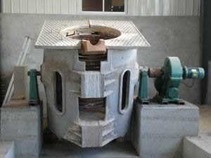
Induction heating principle of tandem induction melting furnace
For induction heating of thyristor passive series induction melting furnace , single-phase half-bridge series induction melting furnace is the most widely used ; single-phase full-bridge passive series intermediate frequency power supply is more common in the field of low power. Regardless of the full bridge or the half bridge, the load is a series tank circuit; the tank circuit excitation method is a square wave controlled by an inverter switch, and the tank circuit response is a constant amplitude sinusoidal oscillation (positive half cycle); the inductor realizes electrothermal conversion. The switching frequency and phase are mostly controlled by a frequency closed-loop system composed of tank circuit current signals (also useful tank circuit voltage signals). The basic circuit structure of the series resonant inverter power supply is shown in Figure G-1 .
Figure G.1 Block diagram of a single-phase passive series inverter induction melting furnace
As far as system control is concerned, the full bridge is basically the same as the half bridge. In the inverter bridge of the half-bridge series inverter power supply, the position of the thyristor of the missing half-bridge is replaced by a resonant capacitor to form a double-slot compound series resonant circuit. The general excitation power source-DC constant voltage source is always constant at the rated value, that is , the voltage does not change. After the constant voltage source is the three-phase rectifier, through . The LC " shaped filter is formed. Although the rectified voltage constant, but the voltage to protect the stability of the current and the like, generally designed as a rectification part independent voltage, current bicyclic structure The self-adjusting control system of voltage fixed value .
The power adjustment of the series (half bridge, full bridge) inverter induction melting furnace is generally realized by changing the power factor of the tank circuit. The power adjustment system is actually a self-adjusting system with no difference in voltage between the outer loop of voltage (intermediate frequency) and the inner loop of current (power frequency, intermediate frequency, DC): voltage setting T, voltage regulator and current regulator together stepping phase logic trigger T trigger inverter frequency control switch (SCR) to T change inductor LH voltage Kh a change RLC tank circuit power factor T control the output power F. .
Full and half-bridge power inverter series regulator, may be implemented by a constant frequency regulator; but the loss will be the main transformer and power factor waste valve Si c tank nominal parameter expense, not recommended engineering. The power regulation of full-bridge and half-bridge series inverter power supplies, whether it is voltage regulation or frequency regulation, is actually a single-variable self-regulating system (also called a fixed-value control system) with a given voltage . Voltage regulation achieves the purpose of power regulation, and the current belongs to the disturbance of the control system.
The triggering of the inverter switch (thyristor) must be synchronized with the tank current. Trigger synchronization is achieved by the frequency automatic tracking link. The automatic tracking link is based on the intermediate frequency current signal (usually taken from the LC tank circuit or the inverter bridge circuit, and the inverter switch thyristor current "180. Time" is measured, which is the natural zero crossing time, as the "reference 0 " for the phase shift of the intermediate frequency current . frequency) and the associated logic circuit , with the step part of the closed loop control. This kind of frequency closed-loop method is called self-excitation method, as shown in Figure G-1 , the frequency and synchronization link.
In the actual operation of the inverter triggering, it is impossible to achieve trigger synchronization due to the drift of the control circuit parameters and the drift of the tank circuit parameters. Separate excitation can only operate in a range far below the resonance frequency; generally, separate excitation is only used for circuit testing before debugging. Heterogeneous excitation is the frequency tracking open-loop trigger, which can only be used in pure resistive or non-resonant variable frequency inverters.
Parallel inverter induction melting furnace . The oscillating current of the tank circuit must be continuous. The inverter bridge requires a stable constant current source. If the current is intermittent, the inverter will fail. Inverter series L C tank circuit oscillation current is interrupted, the inverter bridge requires a stable constant voltage source, if a large voltage intermittent or pulsating, the inverter fails.

