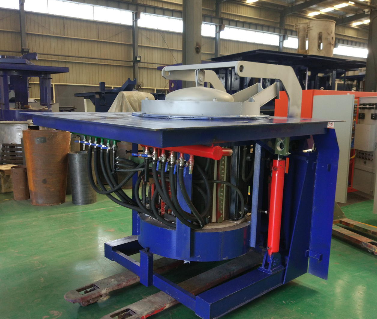
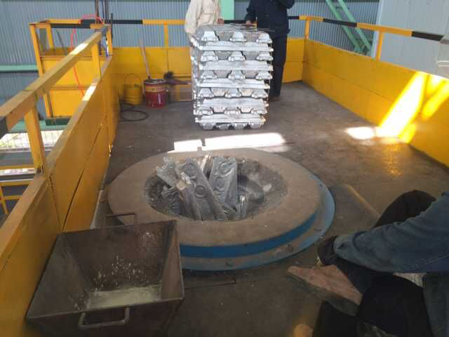
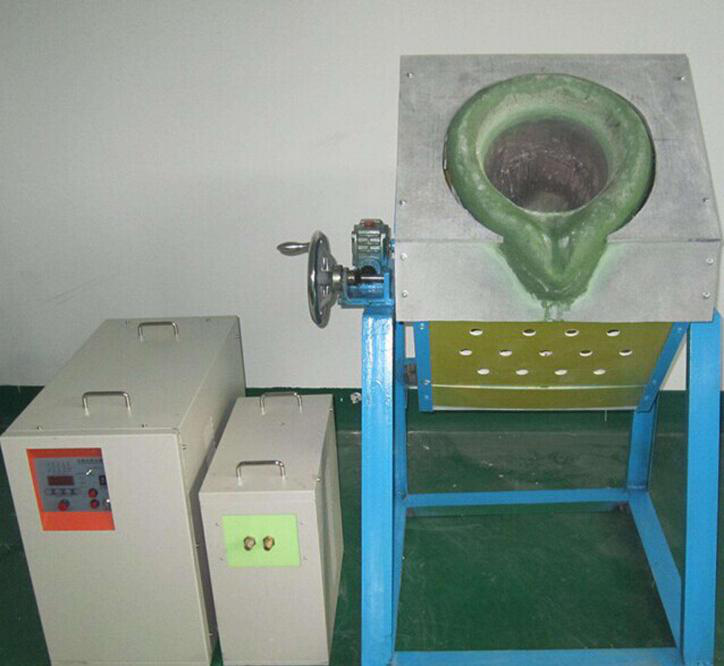
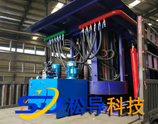
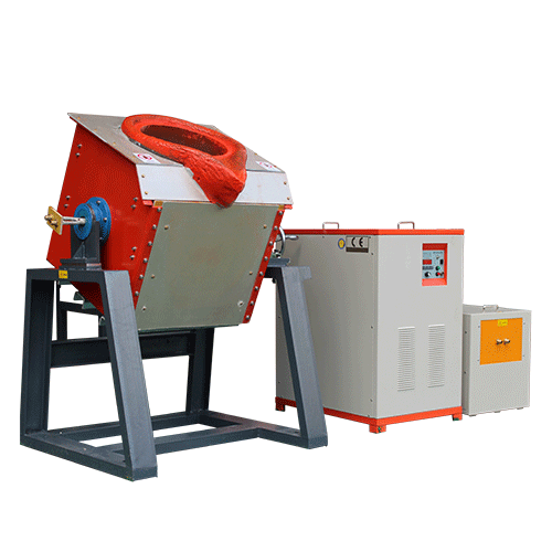
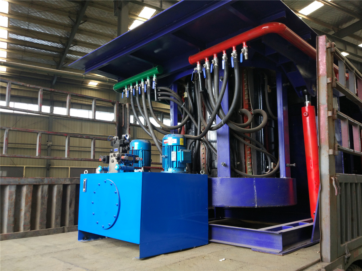
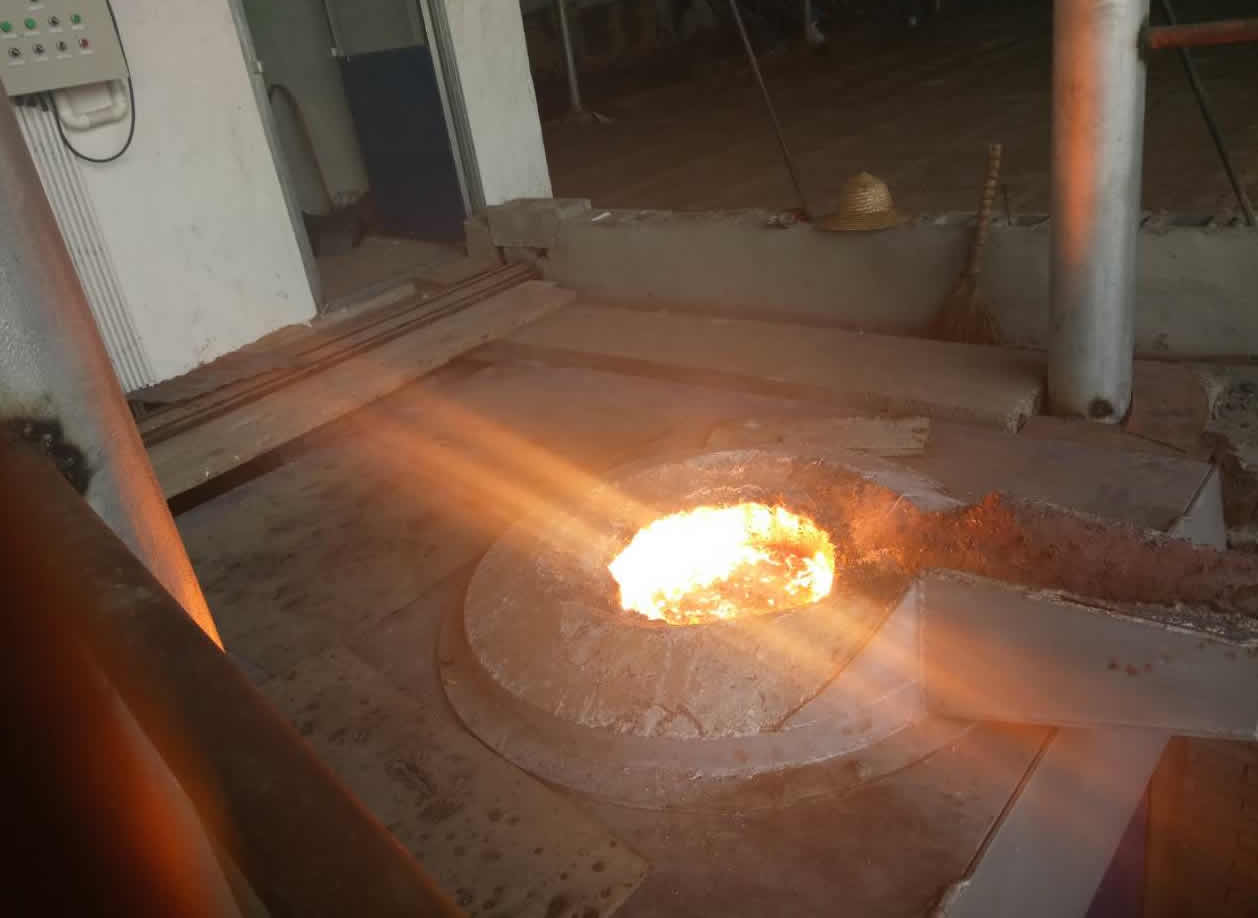
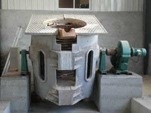
6000kW induction melting furnace harmonic and reactive power compensation device case
A metal products company has a 6000kW induction melting furnace , high voltage 6kV power supply, intermediate frequency power supply equivalent to 12 pulses. Due to the large number of high-order harmonics generated during smelting in the induction melting furnace , the 11th and 13th are the main ones, which seriously threatens the safe operation of the upper-level power supply transformer and makes the compensation capacitor connected to the same power supply network unable to operate normally. In order to eliminate the above influence, a filter compensation device is installed on the 6kV side of the induction melting furnace , which can filter out a large number of harmonic components on the one hand, and on the other hand can compensate the power factor, reduce line loss, and save energy. The effective power frequency capacity of the filter is determined based on the amount of reactive power compensation required by the power factor. The configuration and actual installed capacity of the filter are determined based on the harmonic current spectrum generated by the induction melting furnace and the magnitude of each harmonic current. of. Filter capacity on the premise fundamental and harmonic current determination of other parameters are to be calculated filter, first to the rated voltage of the filter capacitor must be determined, and the rated voltage of the smoothing capacitor is affected by the following factors.
(1) Fundamental current The fundamental voltage applied to both ends of a capacitor.
(2) Harmonic current is the harmonic voltage applied to both ends of a capacitor.
(3) The increase in the voltage across the capacitor after the reactor is connected in series.
(4) Deviations in voltage operation increase the voltage across the capacitor.
After considering the above four factors, the rated voltage of the filter capacitor is calculated to determine the installation capacity of the filter and the capacitor connection method, as shown in Table 2-3 . The filter reactor parameters are shown in Table 2-4 . The resistor parameters are shown in Table 2-5 .
Table 2-3 each receiving filter branch capacitor mounting ■ connected and connection mode
|
Filter branch |
5th branch |
7th branch |
Qualcomm Branch |
total |
|
Installation capacity (three-phase) /kVar |
600 |
1200 |
1350 |
3150 |
|
Capacitor capacity /kVar |
200 |
200 |
225 |
|
|
Number of units used/unit |
3 |
6 |
6 |
15 |
|
Connection method |
1 and / phase |
2 and / phase |
2 and / phase |
|
Table 2-4 Reactor parameters of each filter branch
|
Filter branch |
5th branch |
7th branch |
Gaotong Zhilu |
total |
|
System voltage /kv |
6 |
6 |
6 |
|
|
Quality factor |
30 |
30 |
20 |
|
|
Number of units used/unit |
3 |
3 |
3 |
9 |
Table 2-5 Filter resistor parameters
|
Filter branch |
Resistor model |
Rated voltage /kV |
Rated resistance /Q |
Number of units used |
|
Qualcomm Branch |
GZN6-200 |
6 |
200 |
3 |
The filter sets the following protections:
(1) Overvoltage protection: set according to L1 times of the bus voltage , delay lmin to protect trip;
(2) Under-voltage protection: set at 0.6 times the bus voltage , Os protection trips;
(3) Current quick-break protection: Set at 5 times the rated current of the filter, Os protection trips;
(4) Overcurrent protection: set at 1.5 times the rated current of the filter, 0.5s protection trip;
(5) Three-phase balance protection: Set according to the unbalanced voltage generated after a capacitor fails, and the Os protection trips.
All the above-mentioned protections are realized by microcomputer protection. In addition, for a single capacitor, use fuse protection one by one, and use a gapless zinc oxide arrester for the filter bank to prevent transient overvoltage and operating overvoltage.
The effects before and after the filter compensation device is put into use are shown in Table 2-6 .
Table 2-6 Treatment effect before and after the filter compensation device is put into use
|
project |
Before installation |
After the device is put in |
project |
Before installation |
After the device is put in |
|
Current RMS (average value) /A |
530.43 |
514. 03 |
11th harmonic current value /A |
69.31 |
5.81 |
|
Average power factor |
<0.9 |
>0. 98 |
13th harmonic voltage content/% |
6.44 |
1.78 |
|
6kV bus voltage total distortion rate/% |
16. 34 |
3. 13 |
13th harmonic current value /A |
57.92 |
9. 15 |
|
11th harmonic voltage content/% |
7. 61 |
0.81 |
|
|
|

