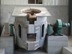
Principle of Induction Melting Furnace-Harmonic Control Method
The traditional induction melting furnace does not control the rectification circuit, that is, bridge rectification followed by a large smoothing capacitor. This circuit will only have current input when the absolute value of the input voltage is greater than the capacitor voltage, so that the input current becomes a kind of The discontinuous waveform is approximately pulsed, and this waveform contains a large number of harmonics. Power devices that use this circuit, such as linear stabilized voltage sources, and most of the popular induction melting furnaces today, basically use this circuit in the front input rectifier part. Phase control converter. The development of power electronics technology, especially the invention of thyristors, has resulted in various current conversion technologies and power control. Since this technology only conducts electricity within a certain phase angle range of each voltage cycle, its input current also has a large amount of input current. Harmonic components, and with the increase of the phase control angle during the voltage regulation process, the power factor of the induction melting furnace decreases; the lower harmonic current in the AC circuit is relatively large. Such devices, such as various inverter and chopper devices powered by DC voltage, whose DC power is obtained by a phase-controlled rectifier circuit.
It can be seen from the above that most of the pollution sources that cause harmonics are the power supply part of the induction melting furnace, especially the AC-DC part. Therefore, improving the existing rectifier devices and improving their input current waveform is the most fundamental way to reduce harmonic pollution.
Harmonic control method
At present, the following methods can be used to control harmonics:
(1) Isolation, shielding and grounding of induction melting furnace: the power supply of the induction melting furnace system is independent of the power supply of other equipment. Or install isolation transformers on the input side of induction melting furnaces and other electrical equipment. Or put the induction melting furnace in a human iron box, and the iron box shell is grounded. At the same time, the output power of the induction melting furnace should be laid as far away as possible from the control cable (not less than 50mm spacing), and it must be placed as close as possible to cross at an orthogonal angle; when it must be laid in parallel, the length of the parallel section should be shortened as much as possible (no more than 1mm). And make the steel pipe electrical connection and reliable grounding.
(2) Install AC reactor and DC reactor: when the induction melting furnace is used in the distribution transformer with a capacity greater than 500KVA, and the transformer capacity is greater than 10 times the capacity of the induction melting furnace, an AC reactor should be installed on the input side of the induction melting furnace Device. When the three-phase output voltage of the distribution transformer is unbalanced, and the unbalance rate is greater than 3%, the peak current of the induction melting furnace is too large, which will cause the wire to overheat, and an AC reactor must be installed at this time. In severe cases, a DC reactor must be installed.
(3) Install passive filter: Install the passive filter on the AC side of the induction melting furnace. The passive filter is composed of L, C, and R components to form a harmonic resonance circuit. When the harmonic frequency of the LC circuit and a certain When the frequency of the primary high-order harmonic current is the same, the high-order harmonic current can be prevented from flowing into the power grid. Passive filters are characterized by low investment, high frequency, simple structure, and reliable operation. Easy to maintain. The disadvantage of passive filters is that filtering is susceptible to the influence of system parameters, which may amplify certain sub-harmonics, consume a lot of money, and are bulky.
(4) Install a source filter: As early as the early 1970s, Japanese scholars put forward the concept of an active filter. The active filter passed the middle and high order of the current. Harmonics are detected. According to the detection results, input currents with opposite phases to the higher harmonic components to achieve the purpose of real-time compensation of harmonic currents. Compared with passive filters, it has a high degree of controllability and rapid response, and has the characteristics of one machine and multiple functions. And it can eliminate the danger of resonance with the system impedance. It can also automatically track and compensate the changed harmonics. But it has the characteristics of large capacity and high price.
(5) Installation of reactive power static reactive power compensation device: For large impact loads, a reactive power static reactive power compensation device can be installed to compensate for the rapidly changing reactive power demand of the load and improve the power factor , Filter out the system harmonics, reduce the injection of harmonic currents into the system, stabilize the bus voltage, reduce the three-phase voltage imbalance, and improve the power supply system's ability to withstand harmonics. Among them, the self-saturated reactance type (SR type) has the best effect. It has fewer electronic components, high reliability, fast response, convenient and economical maintenance, and can be manufactured by general transformer factories in my country.
(6) Line separation: Because of the impedance in the power system, the harmonic load current will cause the harmonic voltage distortion of the voltage waveform. Separate the power supply lines of the loads that generate harmonics from the power supply lines of the loads that are sensitive to harmonics. Linear loads and nonlinear loads are fed by different circuits from the same power interface point PCC, so that the distortion voltage generated by the nonlinear load will not Conducted to the linear load.
(7) Multiplexing and diversification of the circuit: The parallel diversification of the inverter unit is to use 2 or more inverter units in parallel, and the harmonic components are offset through the waveform shift and superposition; the multiplexing of the rectifier circuit is to use 12 pulses Wave, 18-pulse, and 24-pulse rectification can reduce harmonic components; the series multiplexing of power units uses multiple pulses (such as 30-pulse series), and the multiple circuits of power units can also reduce harmonic components. In addition, there are new variable frequency modulation methods, such as voltage vector deformation modulation.
(8) Improving the control method of induction melting furnace: With the development of high-tech power electronics, microelectronics, computer networks, etc., the control method of induction melting furnace has the following developments: digital control of induction melting furnace, digital use of induction melting furnace Single-chip microcomputer MCS5l or 80C196MC, etc., assisted with SLE4520 or EPLD liquid crystal display to achieve more complete control performance; a combination of multiple control methods, a single control method has its own shortcomings, if these single control methods are combined, they can learn from each other's strengths, thereby Achieve the effect of reducing harmonics and improving efficiency.
(9) Use idealized green induction melting furnace without harmonic pollution: The quality standard of green induction melting furnace is: input and output current are both sine waves, input power factor is controllable, and power factor can be achieved with any load. For l, it can obtain any controllable output power up and down the power frequency.

