Method for detecting the quality of thyristor in induction melting furnace
Induction melting furnace thyristor, also known as thyristor rectifier, is widely used in controllable rectification, AC voltage regulation, non-contact electronic switching, inverter and frequency conversion and other electronic circuits, playing a very important role, therefore, the intermediate frequency The detection of the quality of the electric furnace thyristor is very important.
1. A rough judgment method using a multimeter
Usually the most commonly used detection tool on the user's site is a multimeter. Many users are also accustomed to using a multimeter to judge whether the device is good or bad. In some cases, it is indeed possible to detect a damaged device with a multimeter. If the thyristor gate is open, a multimeter can be used to detect the gate-to-cathode resistance RGK infinity; the gate short circuit can detect that the gate-to-cathode resistance RGK is zero (or less than 5W). When the device is completely broken down, it can be judged by using a multimeter to detect the resistance values of the A and K poles. However, when the device blocking voltage is damaged and the breakdown is not completely broken, the multimeter cannot be detected. In addition, due to the parameter dispersion, the A and K resistance values detected by the multimeter will have a large difference, which will also cause the user to make a wrong judgment. Therefore, we recommend that users can use the multimeter to perform some rough detection on the device. It is generally not recommended to use a multimeter to judge whether the device is good or bad.
2. Recommended simple detection program
Often, the field service personnel and maintenance personnel need to understand the blocking voltage capability of the device and the gate triggering performance of the thyristor. According to the conditions on the equipment site, we recommend the simple detection scheme shown in Figure 1.
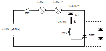
DUT is the device under test. When the DUT blocking voltage is about 1000V (must be greater than 800V), it can be tested with AC 380V power supply; in some cases with 660V AC power supply, the DUT blocking voltage is about 2000V (must be greater than 1200V) The AC 660V power supply can be used for testing. D1 can be used in 1-5A, and voltage diodes above 1000V can be connected in series only. LAMP is the detection indicator. Note that the rated voltage of the lamp should match the incoming AC voltage. If a 220V bulb is used, multiple series connections can be used depending on the incoming line voltage. When the device under test is a diode, the two devices are connected to the circuit as shown by the dotted line, and the resistor R and the switch SW2 are not required.
For the thyristor, when testing, first close the switch SW1. If the indicator light is on, it indicates that the device has been broken down or the voltage is not enough. If the indicator light is off, the device blocking voltage is normal. If the button SW2 is pressed, the indicator light is on, the button is released, and the indicator light is off, indicating that the device's gate triggering performance is normal. If the button SW2 is pressed, the indicator light does not illuminate, indicating that the device gate has been damaged.
For the diode, when testing, close the switch SW1. If the indicator light is off, the reverse voltage of the two devices is normal. If the indicator light is on, it means that one or two reverse voltages of the two devices under test have been damaged, and the device can be replaced for further judgment.
3. Attention
a. The basic idea of the detection method recommended in this paper is to let the device be evaluated under the actual use voltage environment. The user must ensure that the voltage of the device under test is higher than the peak value of the incoming line voltage during the test to avoid damage to the device during the test.
b. For Taiwan-based flat-panel devices, the user must apply appropriate clamps to the devices to apply pressure to the electrodes A and K. Failure to do so may result in incorrect judgment due to poor internal contact.
c. When using a higher line voltage detection device, the operator must take safety measures to prevent electric shock and ensure personal safety.

