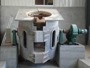
Mechanical structure and use environment of induction melting furnace intermediate frequency power supply
1. Mechanical structure
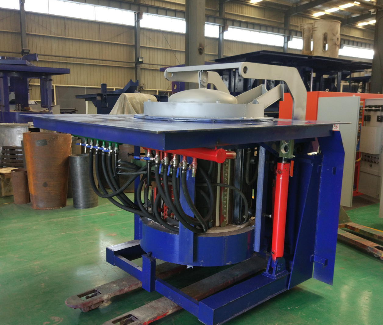
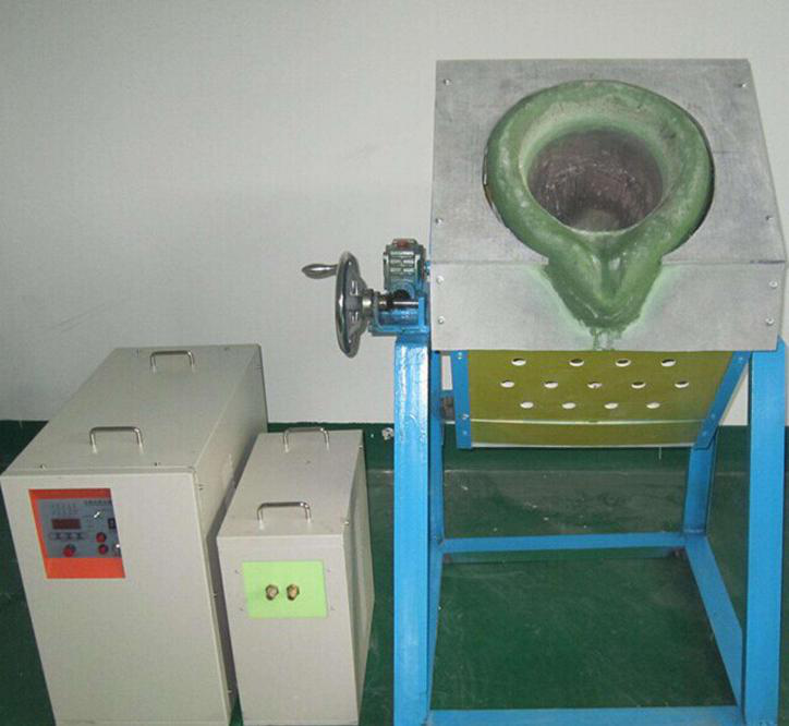
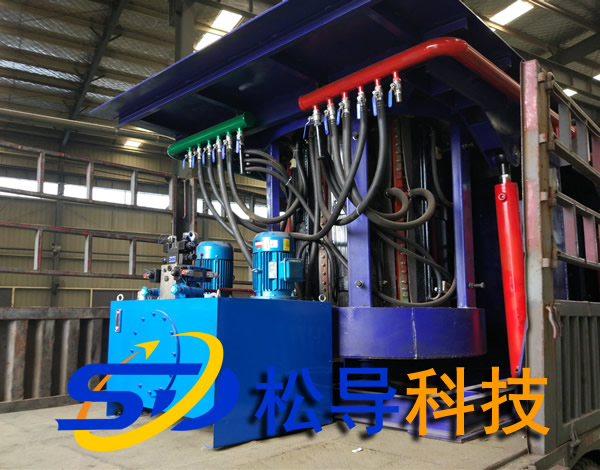
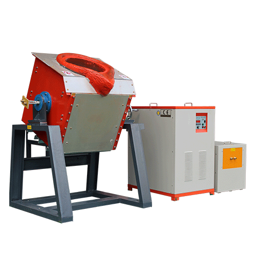
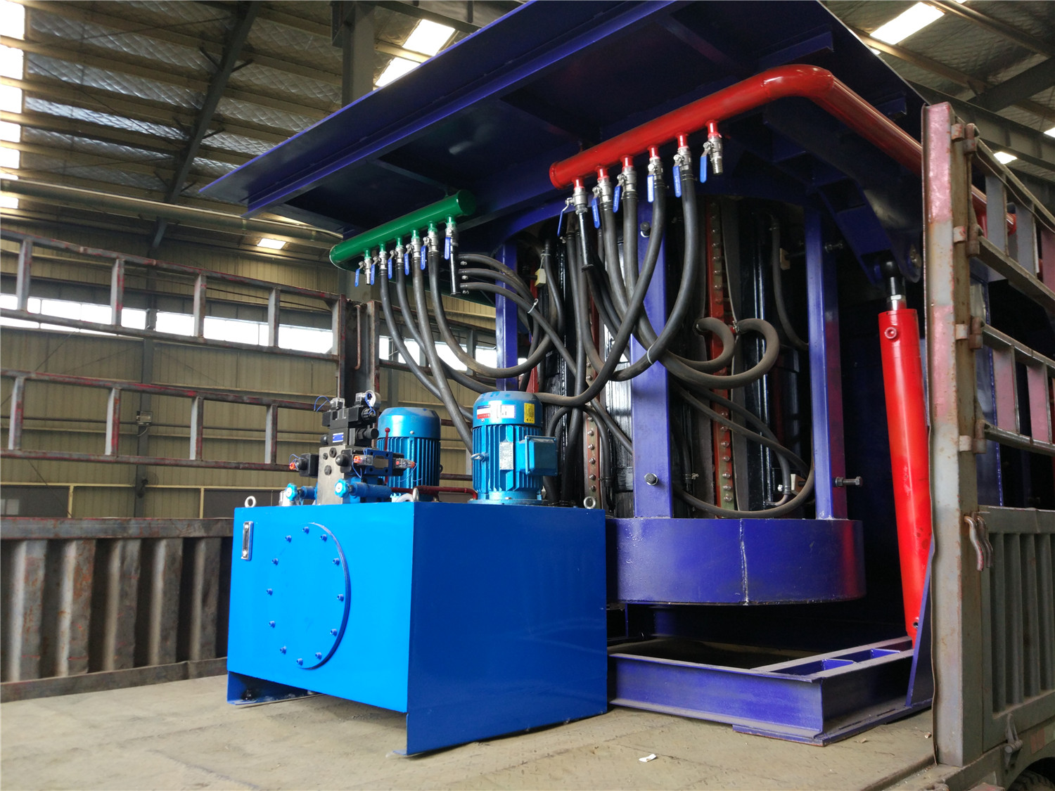
The mechanical structure of the induction melting furnace power supply stipulates items such as the shape, dimensions and tolerances of the chassis, the assembly position, the length of the assembly holes and screws, the material and surface treatment of the chassis, cooling conditions (such as forced air cooling or natural cooling), and ventilation. Direction and air volume and opening size, external temperature rise, interface position and display, position of operating parts and position of text display, quality of power supply equipment, etc.
2, the environment of the intermediate frequency power supply and other conditions
The specified operating temperature range varies with the place of use. Commercial grades are generally 0 to 50 ° C, storage temperatures are generally -25 to 75 ° C; industrial grades are generally -25 to 50 ° C, and storage temperatures are generally -40 to 75 ° C. The military grade is generally -40 to 55 ° C, and the storage temperature is generally -55 to 75 ° C. When used in a place where the temperature changes abruptly, it is necessary to specify the temperature slope, which is generally within 15 ° C / h. The specified relative humidity range is 20y-6~85%, and the storage relative humidity range is generally 18%~90%. There must be corresponding indication when dew condensation. Generally, the environment at normal temperature and normal humidity is 15 to 35 ° C and 25% to 85%. For vibration-resistant regulations, the vibration force is 0.5 to 1. OG when operating at a vibration frequency of 10 to 55 Hz, and 2.5 to 4 G when not working. The impact resistance varies with the power supply product, which is 10 to On the order of 100G. The noise regulations include input noise, lightning surge, and static noise. The input noise is caused by the pulse voltage superimposed on the power frequency. The pulse width is generally 100-800 utS, and the applied voltage is lO0OV. Recently, the pulse width is several milliseconds and the voltage is several hundred volts. The lightning surge regulations are several thousand volts for communication equipment, typically 1200V. The specification of static noise varies with capacitance capacity and series resistance value.

