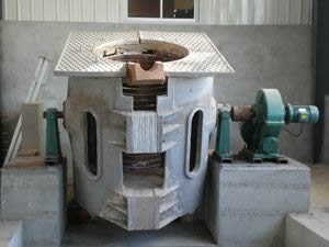
Five major fault repairs in induction melting furnaces
1. Power supply: Use a multimeter to measure the main circuit switch (contactor) and control the fuse behind the power, which will eliminate the possibility of these components open circuit.
2. Rectifier: The rectifier uses a three-phase fully controlled bridge rectifier circuit, which includes six fast fuses, six thyristors, six pulse transformers and one freewheeling diode.
There is a red indicator on the quick fuse. When the indicator is normal, it will shrink inside the housing. When the fuse is blown, it will pop out. Some fast-melting indicators are tight. When the fuse is blown, it will get stuck inside. Therefore, for the sake of reliability, you can use the multimeter on/off to measure the fast-melting to determine if it is blown.
A simple way to measure a thyristor is to measure its cathode-anode, gate-cathode resistance with a multimeter electrical barrier (200Ω block). The thyristor does not need to be removed during measurement. Under normal circumstances, the anode-cathode resistance should be infinite, and the gate-cathode resistance should be between 10 and 50 Ω. Too large or too small indicates that the thyristor gate is ineffective and will not be triggered to conduct.
The pulse transformer is connected to the thyristor on the secondary side, and the primary side is connected to the main control board. The primary side resistance is about 50Ω measured by a multimeter. The freewheeling diode is generally not prone to failure. When checking, the multimeter diode is used to block the two ends. In the forward direction, the multimeter shows that the junction voltage drop is about 500mV, and the reverse is not possible. 3
3. Inverter: The inverter consists of four fast thyristors and four pulse transformers, which can be inspected as described above.
4. Transformer: Each winding of each transformer should be open. Generally, the primary side resistance is about tens of ohms and the second pole is a few ohms. It should be noted that the primary side of the IF voltage transformer is connected in parallel with the load, so its resistance is zero.
5. Capacitor: The electrothermal capacitor connected in parallel with the load may be broken down. The capacitors are generally grouped and mounted on the capacitor holder. The inspection should be performed to determine the group in which the capacitor is broken. Disconnect the connection point between the busbar of each group of capacitors and the main busbar, and measure the resistance between the two busbars of each group of capacitors. Normally, it should be infinite. After confirming the bad group, disconnect the soft copper from each electric capacitor to the busbar, and check the breakdown capacitors one by one. Each electric heating capacitor is composed of four cores, the outer casing is one pole, and the other pole is respectively led to the end cover through four insulators. Generally, only one core is broken down, and the lead wire on the insulator is tripped. The capacitor can continue to be used, and its capacity is 3/4 of the original. Another fault of the capacitor is oil leakage, which generally does not affect the use, but pay attention to fire prevention.

