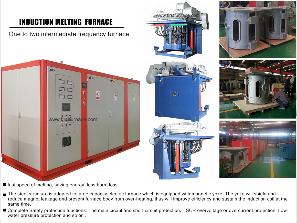
Sales hot line ( 24 hours service): 18037961302
E-Mail: firstfurnace@gmail.com
whatsapp:+8618037961302
Adress: Luoxin Industrial Park, Luoyang, HenanLarge diameter steel pipe quen
Piston rod quenching and tempe
Grinding rod quenching and tem
High frequency induction heate
Quenching equipment for machin
Round steel end heating furnac
Steel pipe heat treatment prod
Square steel quenching and tem
Sucker rod quenching and tempe
Thickened petroleum steel pipe
Round steel quenching and temp
Steel pipe quenching and tempe
Steel plate quenching and temp
Induction Hardening Machine&nb
Flywheel ring gear high freque
Important technical description of 10T/6500KW/250Hz induction melting furnace
Important technical notes
1. The total important technology of the system
|
Serial number |
Term project |
Reference number |
Preparation Note |
|
1 |
Power incoming line voltage |
1250V ,50Hz |
User grid voltage 10KV |
|
2 |
Rated Capacity |
10T |
6500KW power smelting |
|
3 |
rated power |
6500KW (1250V×2 incoming line) |
6-phase 12-pulse control system |
|
4 |
Rated intermediate frequency |
250 Hz |
|
|
5 |
Rated temperature |
1650°C |
|
|
6 |
Melting rate |
About 10T/H |
|
|
7 |
Unit power consumption |
About 520-600kwh/T |
|
|
8 |
Power cooling circulating water consumption |
38T/H |
|
|
Circulating water consumption of furnace cooling |
35T/H |
|
|
|
9 |
Hydraulic station capacity |
250 L |
|
|
10 |
Transformer model |
ZSS-8000 /10KV/1250 |
A special rectifier transformer (for 8000KW) |
|
11 |
Hydraulic medium |
No. 46 hydraulic oil |
|
|
12 |
Water supply pressure |
0.2-0.3 MPa |
To the position of the electric furnace port |
|
13 |
Working pressure of hydraulic station |
15 MPa |
Z height 18 MPa |
|
14 |
Inlet water temperature |
(35℃ |
|
|
15 |
Outlet temperature |
(55℃ |
|
Our company refers to and integrates the advantages of domestic and foreign intermediate frequency induction melting furnaces, based on the principles of reasonable structure, advanced technology, practicality and reliability, and convenient maintenance. Compared with ordinary lines, the 20T intermediate frequency induction melting furnace has obvious energy-saving effects and can be saved. Electricity is about 5%. Due to very few connections, the failure rate can be reduced by 90% and debugging and maintenance are simple.
1. Main technical parameter requirements of 10T/6500KW intermediate frequency induction melting furnace
This set of induction melting furnace complies with GB5959.3 "Safety of Electric Heating Equipment Part III Special Requirements for Induction and Conductive Heating Equipment and Induction Melting Equipment", GB10067.3 "Basic Technical Conditions of Electric Heating Equipment Part 3 Induction Electric Heating Equipment" and JB4280 "Intermediate frequency coreless induction furnace" requirements.
2. Project Quotation of 10T/6500KW Intermediate Frequency Melting Furnace Project
|
Serial number |
Name called |
Model and remarks |
Quantity |
price (Ten thousand yuan) |
|
1 |
IF power supply cabinet |
6500KW with 10 tons furnace |
1 set |
|
|
2 |
Capacitor bank |
|||
|
3 |
Leaking furnace alarm device |
|||
|
4 |
Furnace body (including: oil steel, iron core, bracket, induction coil, etc. ) |
10T melting furnace body |
1 set |
|
|
5 |
Crucible mold |
|
||
|
6 |
Water-cooled cable |
Water-cooled cable side outlet |
1 set |
|
|
7 |
Hydraulic station system |
|
1 set |
|
|
8 |
External control console |
|
1 set |
|
|
9 |
Equipment technical drawings |
|
1 set |
|
|
10 |
Equipment instruction manual |
|
1 set |
|
|
11 |
Certificate of conformity and inspection report |
|
1 set |
|
|
total |
The total price of the complete set of equipment is: |
|||
3. Major component manufacturers (a well-known manufacturer)
1. Power supply cabinet:
⑴ main circuit breaker Shanghai People's Electric Factory or West Germany DW Series
DW15--2500
⑵ "Xianfeng" brand of rectifier SCR Hubei Xiangfan Power Electronics Group Co., Ltd.
KP 2000A 3000V 12 pcs
⑶Inverter SCR "Xianfeng" brand of Hubei Xiangfan Power Electronics Group Co., Ltd.
KK2500A 2800V 16 pcs
⑷ Self-made main control board
⑸ buttons, lights, etc. Shanghai Second electrical plant
⑹Resistance and capacitance to protect SCR 794 factory and 795 factory
⑺ Copper row 8*100 Luoyang Copper Material or Zhejiang Shangyu Copper Material Factory
2. "Weiwei" brand of electric heating capacitor Xin'anjiang Capacitor Factory
1.7—2000—0.25S
3. Furnace body :
⑴Induction coil copper tube Luoyang Copper Material or Zhejiang Shangyu Copper Material Factory
⑵Silicon steel sheet Wuhan Iron and Steel Company
⑶ cylinder Sichuan Changjiang Hydraulic Parts or Yuci Group
4. Hydraulic system:
⑴Hydraulic components Beijing Huade Hydraulic Group Co., Ltd.
⑵Oil pump Shanxi Yuci Group Hydraulic Factory
⑶ Motor Xi'an Motor Factory
5. Transformer Tongniu Transformer Factory
6. Waterway system :
(1) FBT closed cooling self-made
4. Brief introduction of equipment design features
A) Power transformer
This equipment uses a dedicated rectifier transformer (designed and produced according to high altitude, and the following equipment is designed and produced according to high altitude)
Transformer technical parameters rectification:
Model: One ZSS-8000/10 (for 10 ton melting furnace)
Rated capacity: 8000KVA
Rated voltage: 10KV±5%/1250
The transformer used in the intermediate frequency solid power supply is used to reduce the 10KV high voltage to the voltage of the intermediate frequency power supply used. This equipment uses a dedicated rectifier transformer, oil-immersed and self-cooled. The model of the rectifier transformer is ZS-8000KVA. The primary voltage is 10KV , and the secondary voltage is 1250V. The short-circuit impedance range of the rectifier transformer is between 6%-8%. A no-load manual voltage regulating switch is installed on the high voltage side of the transformer, and the output voltage can be adjusted in three gears of -5%, 0, and +5%. The power transformer is equipped with a Buchholz relay and an oil temperature gauge, and its output is interlocked with the high-voltage switchgear. When the transformer has a gas alarm or the oil temperature is too high, it will automatically cut off the high
5. Power supply features: see "Constant Power Digital Control Manual" for details
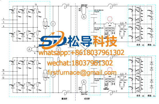
The power supply adopts transverse power control system, 6-phase 12-pulse circuit. It is used for the power control of various metal smelting, heat preservation and induction heating equipment. This technology has reached the leading domestic level.
The power control board is a fully integrated control board for single-board computers, which adopts digital triggering, which has high reliability, high precision, and adjustment.
The maintenance is convenient and simple, the debugging is easy, and the relay components are few.
3. The incoming line of the main circuit can be independent of phase sequence (phase sequence is automatically adjusted).
4. The advanced constant power zero voltage sweep frequency starting technology enables the operator to achieve 100% successful starting without having to select the starting voltage and starting frequency.
5. Inverter control refers to foreign advanced control technologies such as ABB, Pillar, Ajax, Fuji Electric, etc., and has strong anti-interference ability.
6. Automatically follow load changes, with non-faulty automatic restart capability and power automatic adjustment function during operation.
7. It has ideal cut-off, cut-off, precise shut-off time or inverter angle control to ensure reliable operation of the equipment.
8. It has a complete multi-level protection system (water pressure, phase loss, under voltage, over current, over voltage, off time, through, operation interlock, etc.) with high frequency conversion efficiency, greater than 94% for 1000HZ and below.
9. Main circuit parameters:
1) Protection and temperature control
·Main circuit short circuit protection (circuit breaker, main control board protection)
·Main circuit lack phase protection (main control board protection)
·Cooling water pressure low protection (main control board protection)
·SCR overvoltage protection (main control board protection)
·SCR over-current protection (main control board protection)
·Inverter thyristor current rise rate high protection (current transformer protection)
·Insufficient commutation time protection of inverter thyristor (main control board protection)
·Insufficient voltage time protection for reverse turn-off of the inverter thyristor (main control board protection)
·Power supply cooling water temperature, pressure, induction coil water temperature, water pressure and cooling water flow protection have complete detection and protection system settings.
Furnace leakage protection (another dedicated circuit is connected to the main control board for protection)
·Power cooling water temperature and pressure protection.
2) Display and measuring instruments: There are DC ammeter, voltmeter, intermediate frequency voltmeter, power meter, frequency meter on the intermediate frequency power cabinet.
3) Compensation capacitors: all capacitors adopt new large-capacity non-toxic medium water-cooled intermediate frequency capacitors
Three) Furnace body part
1. Furnace characteristics
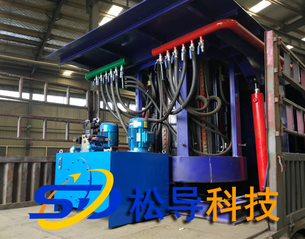
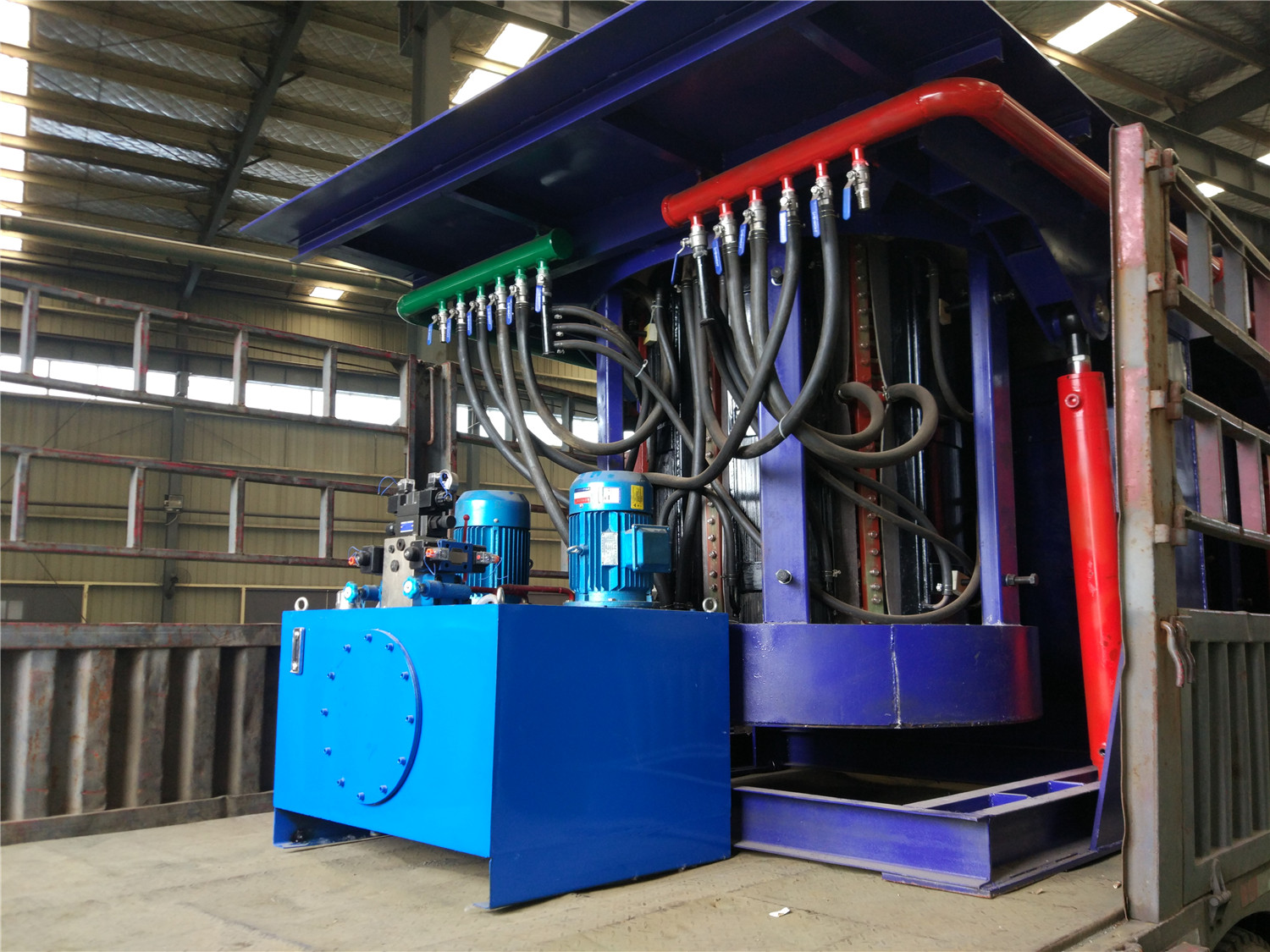
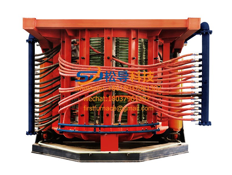
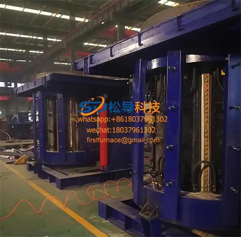
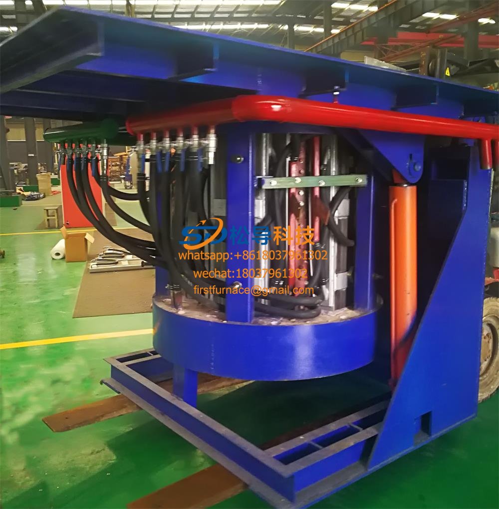
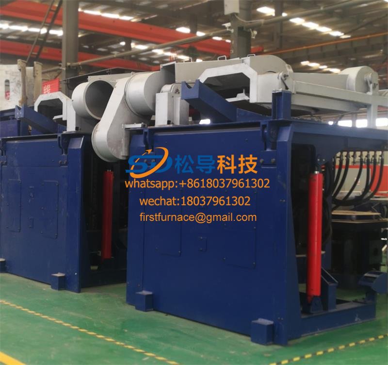
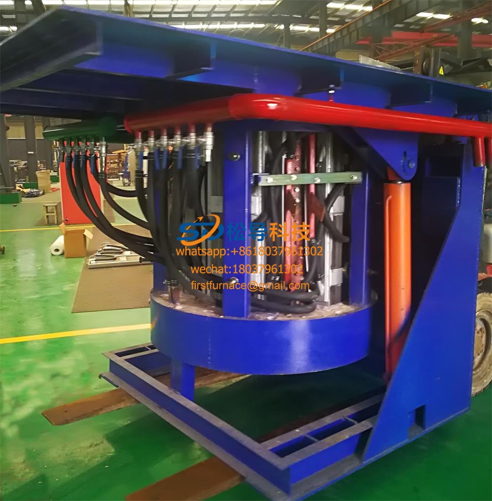
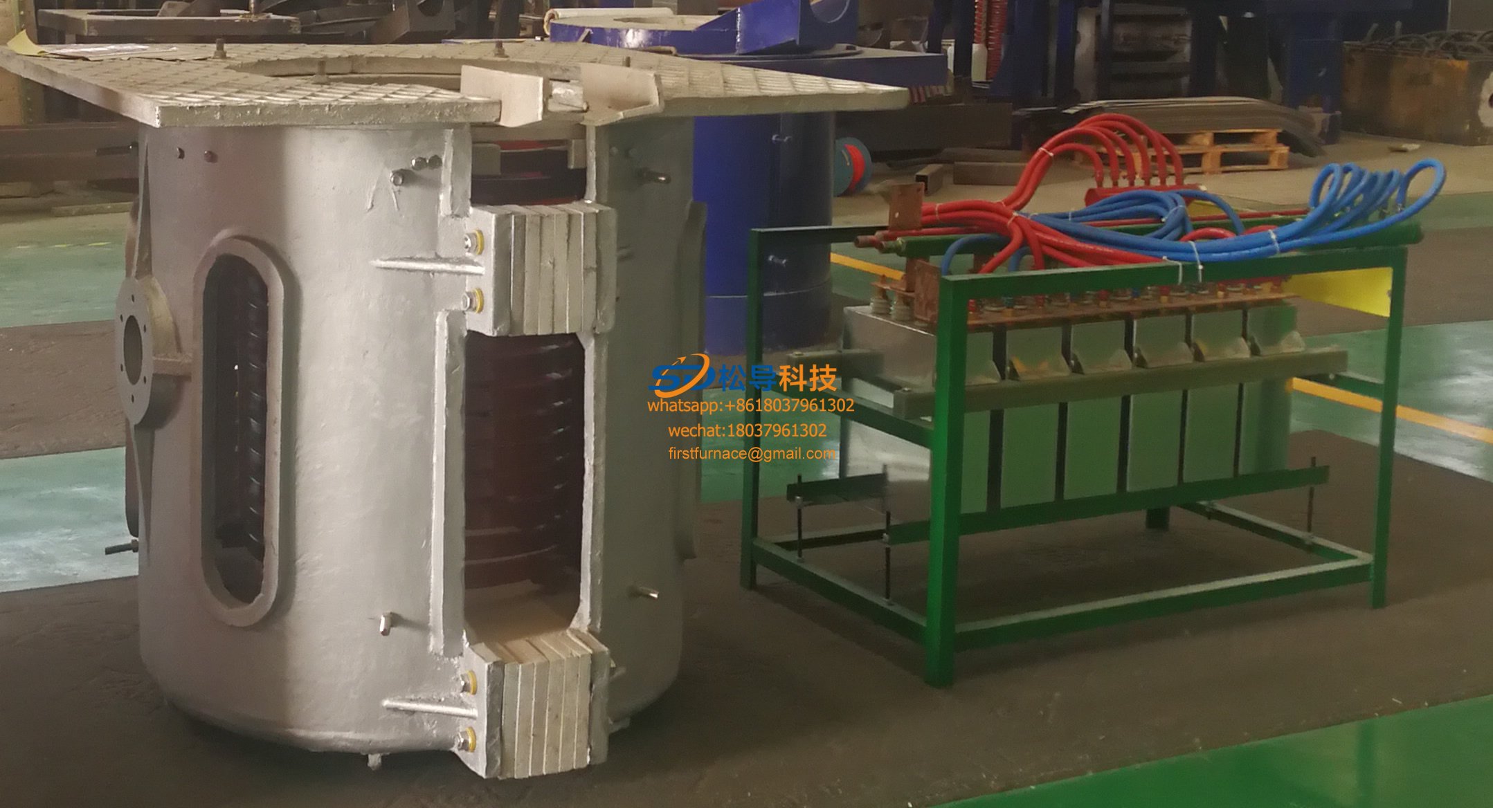
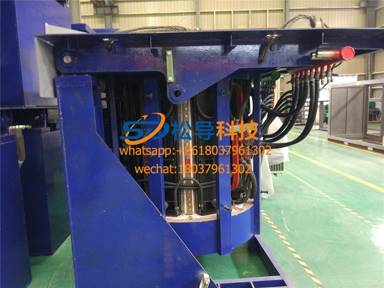
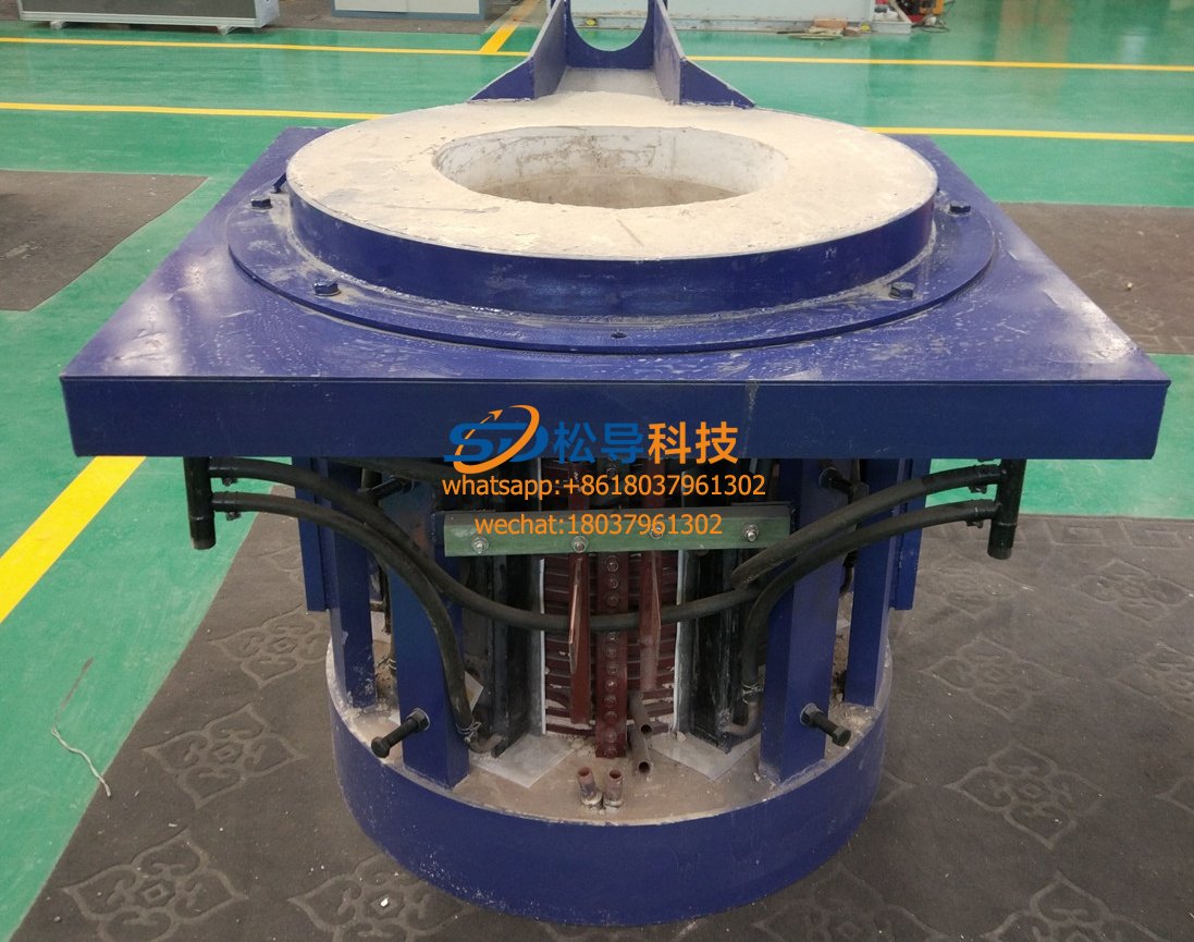
The mechanical part of the intermediate frequency induction furnace is composed of a furnace cover, a furnace body, a fixed frame, a water and electricity introduction system, a hydraulic device, etc.
(2) Furnace body: composed of induction coil, magnetic yoke, furnace frame and leaking furnace alarm device
1) Induction coil
1) The induction coil should be fired with a 99.9% pure oxygen-free copper rectangular thick-walled pipe, the pipe wall thickness is uniform, the water and electricity joints are sturdy and durable, and it is easy to disassemble.
·There are water-cooled coils on the upper and lower parts of the induction coil, so that the furnace lining material is heated evenly in the axial direction, so as to prolong the service life of the furnace lining.
·In order to strengthen the insulation of the induction coil, a layer of high-strength insulating resin should be sprayed on the surface of the coil, and fire-resistant mortar (refractory 1800°C) should be applied to the inner, outer wall and between turns of the induction coil. Because the refractory mortar has a high degree of insulation and heat insulation, it protects the induction coil from damage when the inner lining is damaged.
2) Through years of design and use, we have accumulated certain experience data for its height-to-diameter ratio (H(D)). Sensors of different tonnages have different height-to-diameter ratios. The height-to-diameter ratio of the computer optimized design has greatly improved it. Electric efficiency.
3) The sensor material is made of copper T2
A, copper content 99(95%, B, tensile strength 220K((((
C, stretch rate 45%, D, hardness HB35
4) Sensor design:
The large-tonnage sensor designed by our company adopts the upper and lower sections in parallel, which improves the electrical efficiency of the inductor and is beneficial to production.
Manufacture and improve the mechanical strength, which can reach full power operation under the conditions of half furnace and full furnace. Insulation strength is applied
Rated voltage plus 1000V has no breakdown and flicker. The surface coating is silicone enamel 167, and the insulation resistance is equivalent
The constant voltage is below 1000V, not less than 0.5M(; when the rated voltage is above 1000V, not less than 1M(.
It is produced in strict accordance with the technological requirements of the sensor.
2. Furnace frame: (steel furnace shell)
The movable furnace frame and fixed bracket are based on the original Soviet-style structure, and absorb the advantages of foreign countries such as American Pile, Yingda British Renault, etc., using open squirrel cage, compact structure, good stability, easy heat dissipation and easy maintenance.
Yoke: (steel furnace shell)
The yoke is made of high-quality high-silicon silicon steel sheets (D330 or D43). The conformal yoke is clamped by new stainless steel, which are distributed on the outside of the coil and account for more than 65% of the outer surface of the coil. It is mainly used for magnetic shielding. The magnetic flux outside the inductor can be more concentrated and pass along the yoke with a small magnetic resistance Z to restrict the magnetic flux of the inductor from diverging outward, improve the electrical efficiency of the furnace, and also play a role in fixing and supporting the inductor. The outer layer is coated with alkyd gray enamel, and the insulation resistance shall not be less than 0(5M(.
The yoke is made of high permeability cold-rolled silicon steel sheet with a thickness of 0.30-0.35mm. Z minimizes magnetic loss and improves electromagnetic coupling efficiency.
4. Leaking furnace alarm device
1. During the operation of the crucible induction furnace, cracks are often formed in the furnace lining due to various reasons, leading to furnace leakage accidents. If this kind of accident cannot be discovered in time, the lighter is the damage to the insulation layer of the induction coil and the yoke, the more serious is that the copper tube of the induction coil is burned out, and the high-temperature molten iron contacts the cooling water of the induction coil, causing serious equipment accidents. It even caused an explosion, endangering personal safety. In order to ensure safe production and prevent the occurrence and expansion of furnace leakage accidents, it is necessary to set up a crucible furnace leakage alarm system. The alarm device must be able to send out a furnace leakage alarm signal before the molten iron reaches the sensor. It can judge the severity of the furnace leakage, properly handle the molten iron in the furnace, and reduce the loss to the lowest Z limit.
The leak alarm device is not only a safety protection measure, but also helps to judge the use of the furnace lining and achieve the purpose of extending the furnace life. Because some furnaces do not have a leak alarm device, it is difficult to determine whether the furnace lining can continue after the furnace runs to a certain stage. Use, but fear of leaking the furnace, often remove the furnace lining in advance and re-repair, resulting in unnecessary waste of manpower and material resources.
Working principle of contact leaking furnace alarm device:
2. The principle of the contact leak alarm device is shown in the attached drawing. A stainless steel wire is buried in the bottom of the furnace as the bottom electrode (called Z electrode), which should be in good contact with the molten metal in the furnace. Another electrode (called the second electrode) made of non-magnetic material (such as stainless steel foil, aluminum foil) is installed between the two layers of asbestos plates inside the induction coil. The shape of the second electrode can be made into a fence or dressing, and its height is slightly higher than that of the molten metal in the furnace, and it cannot form a short-circuit ring during installation. A low-voltage direct current is applied between these two electrodes. Under normal circumstances, the furnace lining material and the heat-insulating asbestos board have a large insulation resistance. If the lining is knotted with silica sand, the insulation resistance is in the range of 5~10KΩ, the current is very small (about 10mA at 30V DC voltage), and it is also relatively high. stable. When the molten metal leaks into the furnace lining and contacts the second electrode, causing a short circuit between the Z and the second electrode, the current suddenly increases. When the alarm setting value (about 70~80mA at 30V) is reached, the alarm device will send out a signal and cut the power supply.
This circuit is mainly used as an alarm for furnace leakage, but it can also be used to check the grounding of the main circuit and the low resistance of the cooling water. The switches S1~S5 are closed to perform different inspection functions. For example: S2 and S4 are closed, and the test rod is in contact with the metal in the furnace to check whether the Z electrode lead and the entire control circuit and components are intact; S2 and S5 are closed to check whether the metal is in contact with the copper tube of the induction coil; S1 and S3 are closed It can be checked whether the second electrode is grounded (grounding usually occurs at the lead-out); S1 and S4 are closed, and the test rod is in contact with the furnace molten metal to check whether the molten metal has touched the furnace shell; S1 and S5 are closed to check the main Whether the circuit is grounded; in the leaking furnace alarm state, S2 and S3 are closed.
Four) Hydraulic system: (steel furnace shell)
The valve block of the hydraulic station adopts the integrated block type, which is small in size, and the oil passage is in one direction, which is convenient for the installation of the actuator and the auxiliary equipment of the pipeline.
(2) All hydraulic components adopt joint venture manufacturers and domestic famous brand products.
(3) The tilting of the furnace body is completed by two synchronized plunger cylinders.
(4) The hydraulic device is used to provide power for the tilting furnace cylinder, the furnace cover rotating cylinder and the furnace lining top discharge cylinder. It adopts the form of double pumps and double electricity, and the hydraulic medium is hydraulic oil.
(5) The hydraulic operating table is used to control the tilting and falling of the furnace body, the ejection of the furnace lining and the rotation of the furnace cover, etc. The operations are all realized by the joystick. When the handle is not operated, even if the oil pump is in working condition, the whole system can still be in unloaded condition automatically. Avoid the defects of increased oil temperature caused by operating errors, with high reliability, smooth movement and no impact. Rexroth components are used for hydraulic components.
5) Water-cooled cable:
The joint of the water-cooled cable is crimped with the copper stranded wire by the cold pressing process, and the outer tube of the water-cooled cable is made of a special flame-retardant rubber tube, and can withstand 0.5Mpa water pressure without leakage or rupture.
6) Switch for furnace change (optional equipment):
The furnace change switch is used to switch the furnace body. A double-roll switch and a motor are used to drive this equipment. When the furnace is changed, there is a manual control button on the control panel to control the designated furnace position for furnace change to complete the furnace change action. When the section is switched on, it stays at the original locked position and waits for the next furnace replacement operation command. The control circuit of the furnace changer has a mutual protection function to ensure that the two furnace bodies are not connected to the intermediate frequency solid power supply at the same time.
7) Cooling water system (optional):
1. Plate heat exchanger
The mechanism of the plate heat exchanger is relatively simple. It is composed of stainless plates, sealing gaskets, fixed compression plates, movable compression plates, compression bolts, guide sleeve nuts, upper and lower guide rods and uprights.
The stainless plates of the plate heat exchanger are heat transfer elements. The cold and hot fluids flow in opposite directions on both sides of the plates. The heat of the hot fluid is transferred to the cold fluid through the plates. The plates are 0.6-0.8mm thick. For the rust plate, the thinner the plate, the better the heat exchange efficiency without affecting the bearing capacity. The plates are pressed into herringbone corrugations, so that the fluid forms turbulence when flowing, which increases the heat transfer efficiency and effectively prevents the formation of dirt.
The plate heat exchanger has a compact structure, and only needs to loosen the bolts to move the movable clamping plate backwards during maintenance, unlike the shell-and-tube heat exchanger, which requires a large maintenance space. Also, because the thickness of the selected heat exchange plates of the plate heat exchanger is only 0.6mm~0.8mm, while the shell of the shell and tube heat exchanger is much heavier; therefore, the plate heat exchanger occupies an area when completing the same heat exchange task. Small area and light weight
2. Fully enclosed cold cooling tower
The furnace body and the power supply adopt two independent sets of fully enclosed cooling devices (one set can also be used). The purpose of using two independent sets of cooling devices is to avoid mutual influence. There is a water collecting pan under the cooling tower, which is equipped with spray water. The water inlet of the water collecting pan is equipped with a float valve, which can automatically control the water level in the water collecting pan, and the water outlet is equipped with a spray water pump. Because the intermediate frequency power supply requires low-temperature cooling water, the outlet water temperature should be controlled within 55°C. Since the cooling water temperature of the induction coil of the electric furnace is slightly higher, this can increase the thermal efficiency of the electric furnace and reduce the volume of the cooling device, thereby reducing the cost. The core of the fully enclosed cooling device is a spray evaporative closed cooling tower. There are many cooling coils inside the cooling tower, and the circulating water flows inside the coils without contact with the air. The upper part of the cooling tower is equipped with a water spray and a cooling fan During operation, the spray water pump pumps the water to the upper spray port, spraying the water on the outer surface of the coil in a mist shape, and the cooling fan draws air at the same time, so that the spray water is vaporized and the heat of the circulating water in the coil is taken away. The advanced type of cooling device has high heat exchange efficiency.
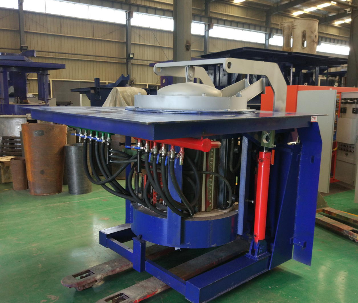
Iron induction furnace
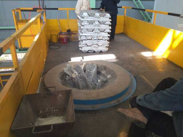
Aluminum melting furnace
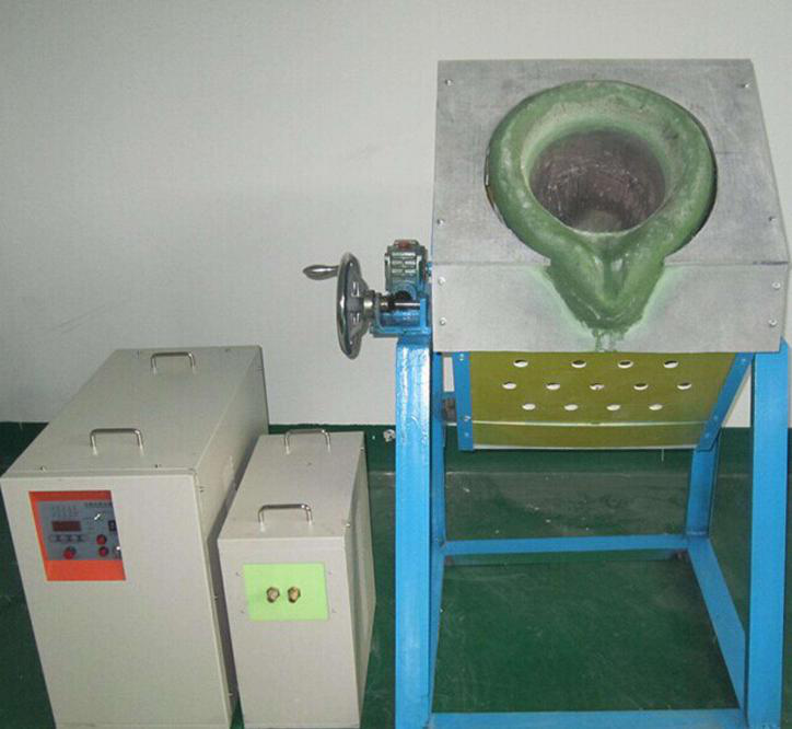
Copper melting furnace
Small steel melting furnace
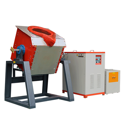
Small induction melting furnace
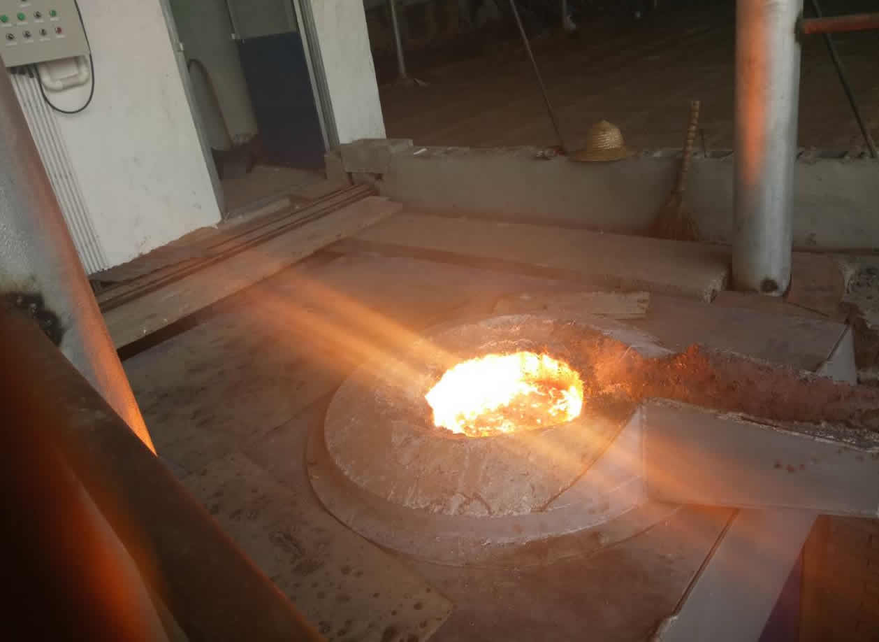
Induction iron furnace
3T intermediate frequency iron melting f
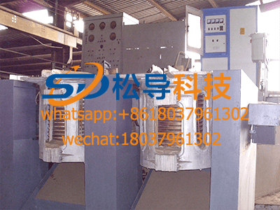
0.25T Intermediate Frequency Furnace
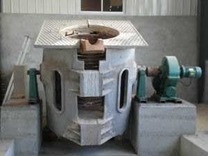
0.5T Intermediate Frequency Furnace
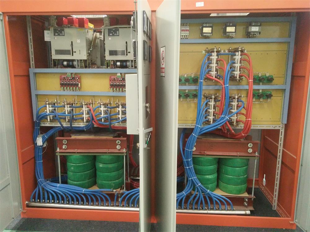
Medium Frequency Furnace

2T Induction Melting Furnace
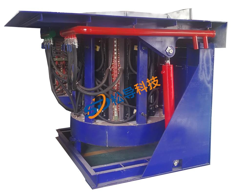
1T Induction Melting Furnace
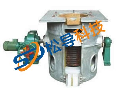
500kg Induction Melting Furnace
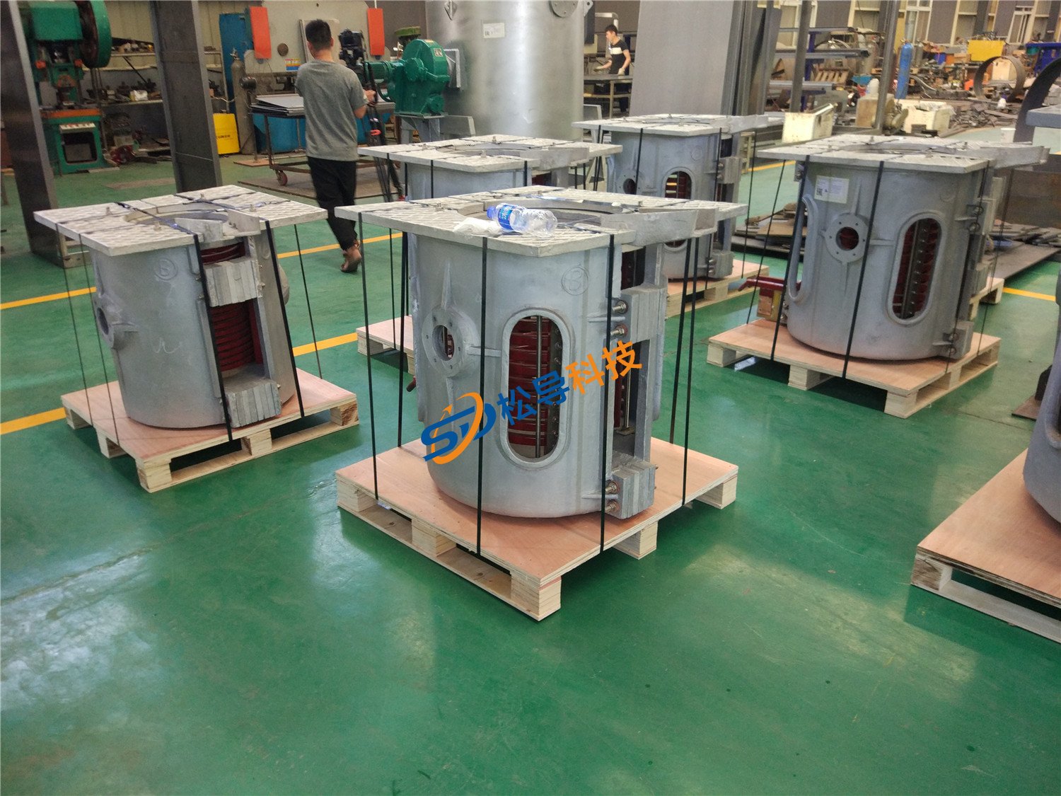
250kg Induction Melting Furnace
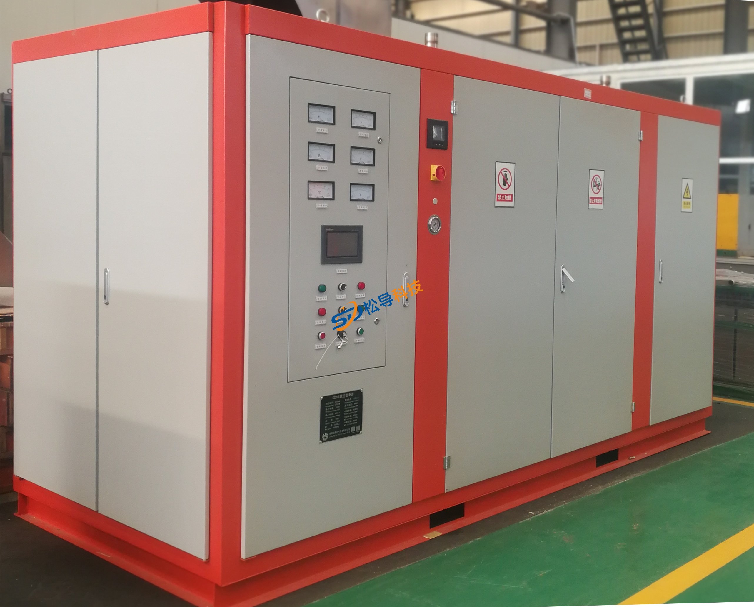
Induction Melting Furnace
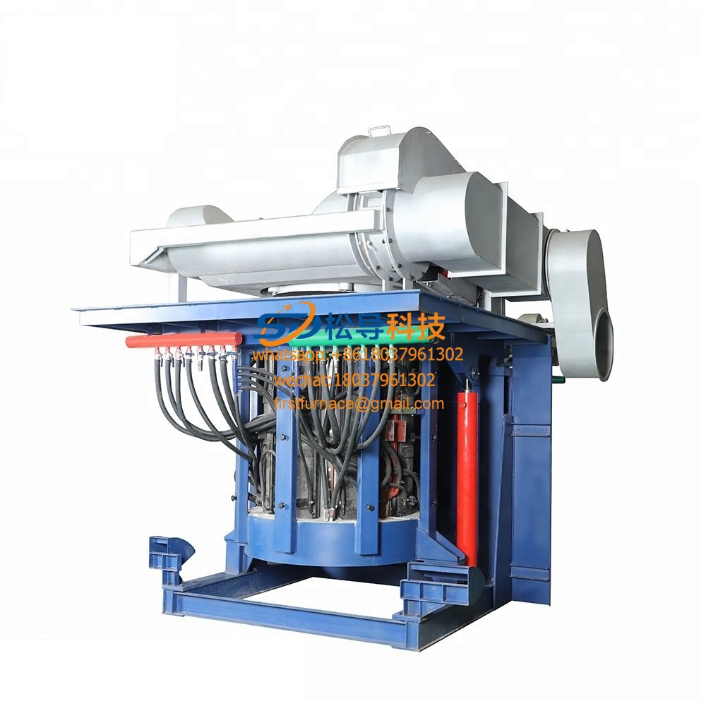
3 T Induction Melting Furnace
5T Induction Melting Furnace
1T One Belt Two Intermediate Frequency F

5T One Belt Two Intermediate Frequency F
3T One Belt Two Intermediate Frequency F
2T One Belt Two Intermediate Frequency F
5T Parallel Intermediate Frequency Furna
5T Intermediate Frequency Furnace

5T Series Intermediate Frequency Furnace
3T Series Intermediate Frequency Furnace
2T Series Intermediate Frequency Furnace
1T Series Intermediate Frequency Furnace
0.5T Series Intermediate Frequency Furna

0.25T Series Intermediate Frequency Furn
1T Parallel Intermediate Frequency Furna
2T Parallel Intermediate Frequency Furna
0.5T Parallel Intermediate Frequency Fur


