Sales hot line ( 24 hours service):+86 13015583380
E-Mail: firstfurnace@gmail.com
whatsapp:+86 13015583380
Adress: Luoxin Industrial Park, Luoyang, HenanLarge diameter steel pipe quen
Piston rod quenching and tempe
Grinding rod quenching and tem
High frequency induction heate
Quenching equipment for machin
Round steel end heating furnac
Steel pipe heat treatment prod
Square steel quenching and tem
Sucker rod quenching and tempe
Thickened petroleum steel pipe
Round steel quenching and temp
Steel pipe quenching and tempe
Steel plate quenching and temp
Induction Hardening Machine&nb
Flywheel ring gear high freque
Induction melting furnace inverter partial detection
main circuit detection
Under the normal condition of rectifying part of the if power supply, if the inverter and if the if load can not start normally, the main circuit wiring of the inverter will be checked first. If normal, but still unable to start, the inverter control board should be checked; if normal, but can not start normally, if the if power load problems. The load circuit shall be tested on a cell by unit basis. The inverter consists of 4 fast thyristors and 4 pulse transformers. The main circuit detection method is the same as the rectifier part.
Inverter control and trigger circuit detection
Connect the oscilloscope to the output end of the intermediate frequency power supply (check and confirm that the reactor, cable, capacitor, furnace body is normal), press the inverter switch, carefully observe whether the if voltmeter has a point up at the moment, whether the oscilloscope has instantaneous AC sinusoidal current, It also shows that the inverter satisfies the oscillation condition, and the angle of voltage and current needs to be adjusted. If no adjustment can be started at all times, it is necessary to detect whether there are any problems with the components, current transformers, intermediate frequency voltage signal
Check if signal transformer is open circuit and short circuit, connect oscilloscope to both ends of coil of intermediate frequency signal transformer, see if there is instantaneous start pulse, if not, if signal transformer has fault. In the case of power outage, if the if signal transformer is further checked with the multimeter ohmic block, if the resistance at both ends of the coil of the intermediate frequency signal transformer is infinite, then it is open circuit; if the resistance is zero, it is short circuit, and the if signal transformer is replaced.
Check whether the current transformer is open circuit or short circuit, connect the oscilloscope to the two ends of the current transformer coil, see if there is any instantaneous start pulse, if there is no instantaneous start pulse, we can judge the fault of the current transformer. In the case of power failure, the multimeter ohmic block is used to further check the current transformer. If the resistance of the secondary coil of the current transformer is infinite, it is open circuit; if the resistance is zero, it is short circuit, replace the current transformer.
If the if signal transformer, current transformer is normal, check the sampling capacitor is normal. If the sampling capacitor is normal, check that the current-voltage plate front potentiometer is normal. Connect the oscilloscope to the two ends of the magnetic plate potentiometer to check if there is a instantaneous start pulse. After checking whether the inverter thyristor KK trigger coil is normal or not, the oscilloscope is connected to the primary two ends of the inverter thyristor KK trigger coil. If there is no instantaneous start of inverter pulse, the fault is in the trigger coil. In the case of a power failure, use a multimeter ohmic block to further check the trigger coil. If the resistance at both ends of the trigger coil is infinite, it is open circuit; if the resistance is zero; otherwise, Short circuit, replace trigger coil.
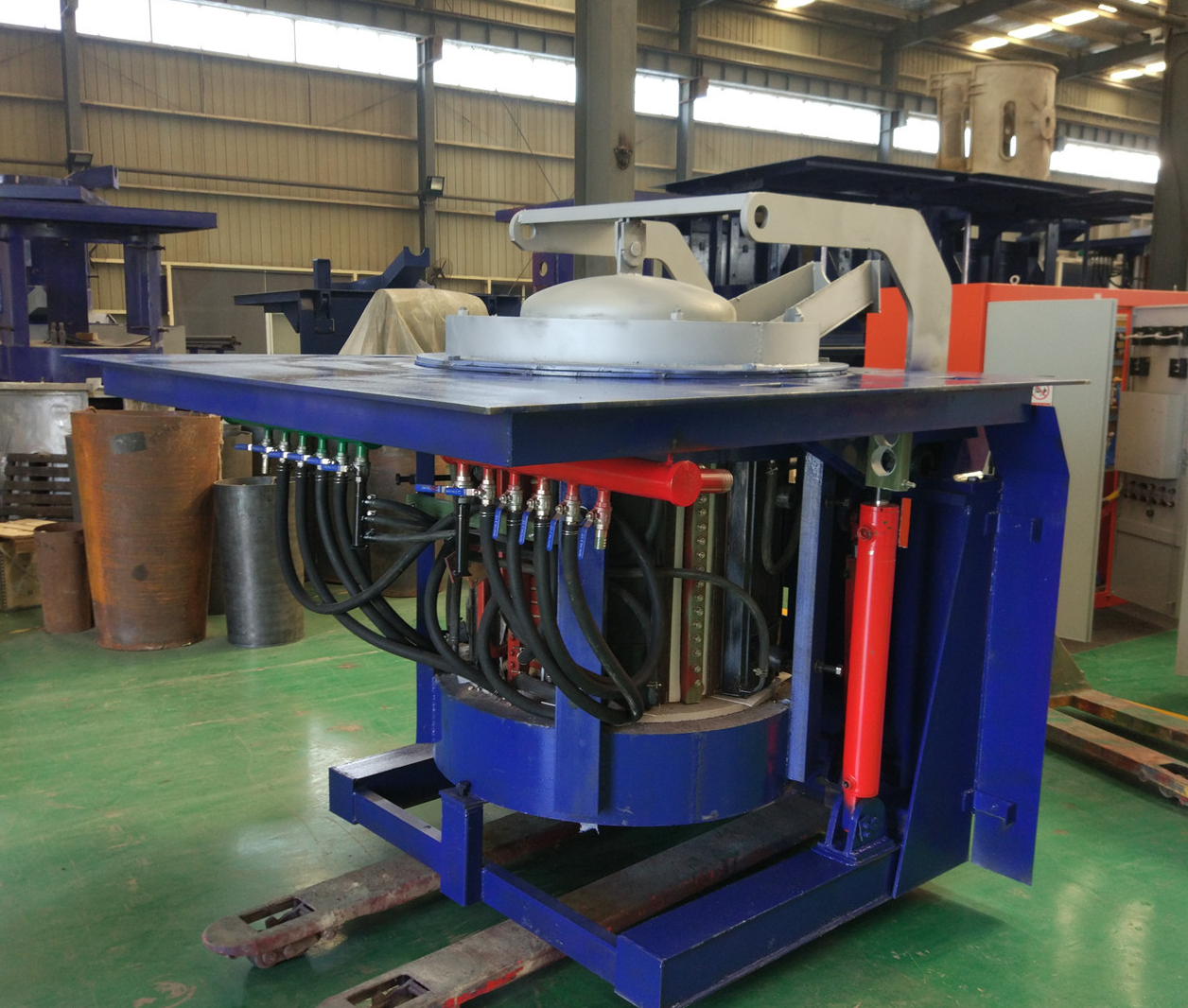
Iron induction furnace
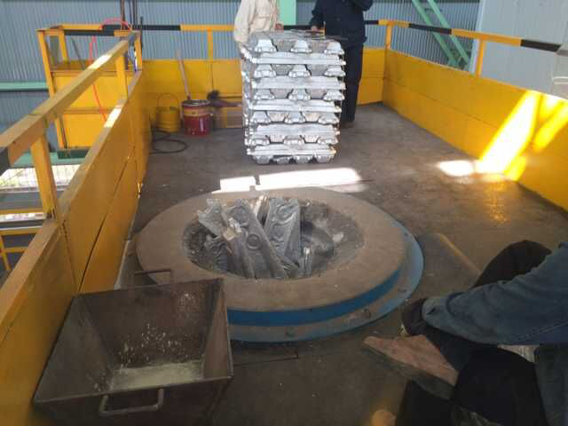
Aluminum melting furnace
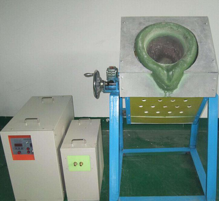
Copper melting furnace
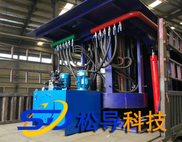
Small steel melting furnace
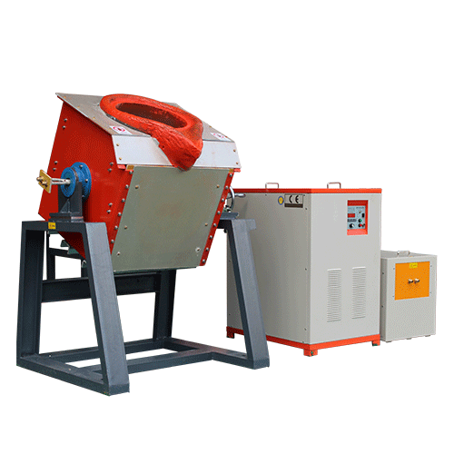
Small induction melting furnace
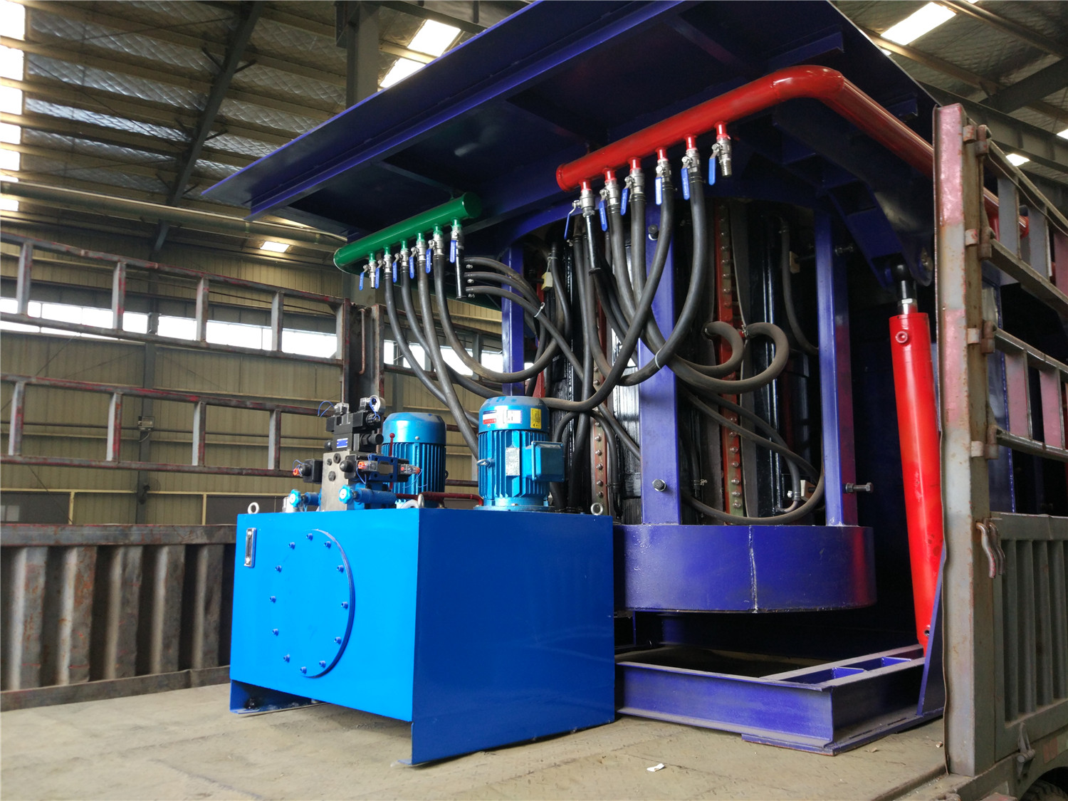
Induction iron furnace
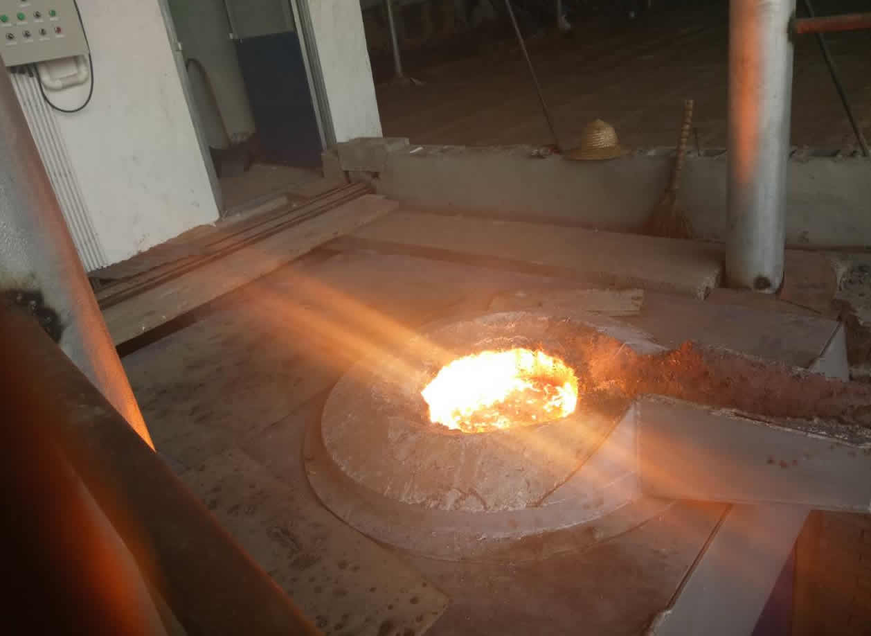
3T intermediate frequency iron melting f
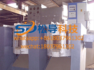
0.25T Intermediate Frequency Furnace
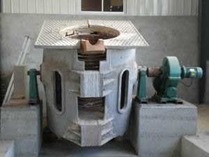
0.5T Intermediate Frequency Furnace
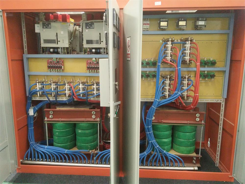
Medium Frequency Furnace

2T Induction Melting Furnace
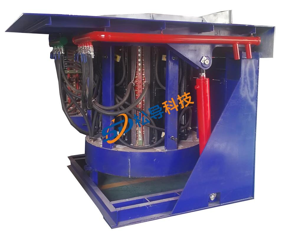
1T Induction Melting Furnace
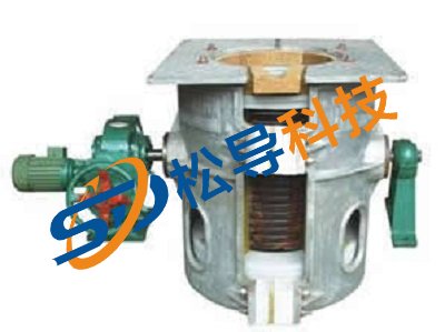
500kg Induction Melting Furnace
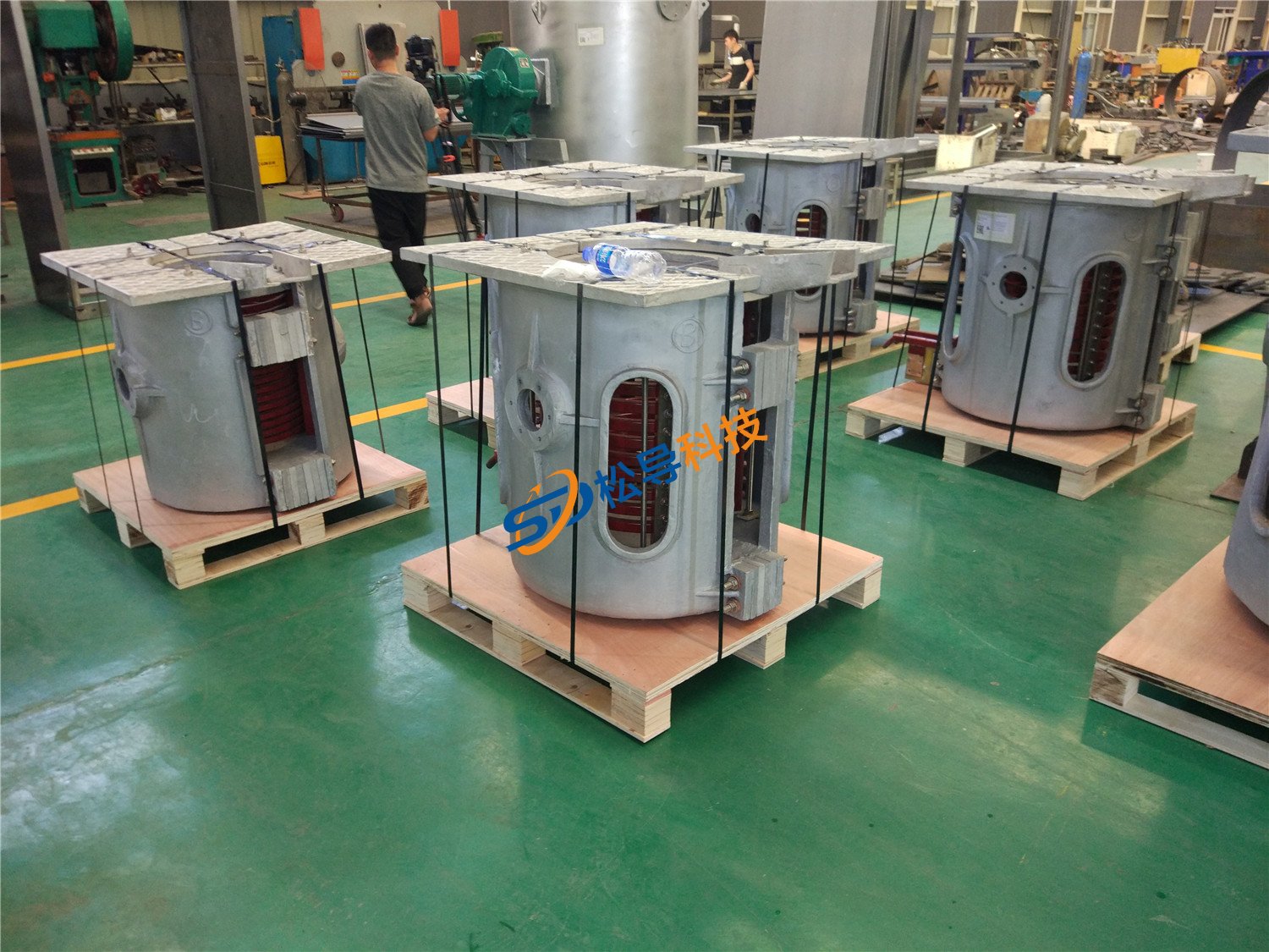
250kg Induction Melting Furnace
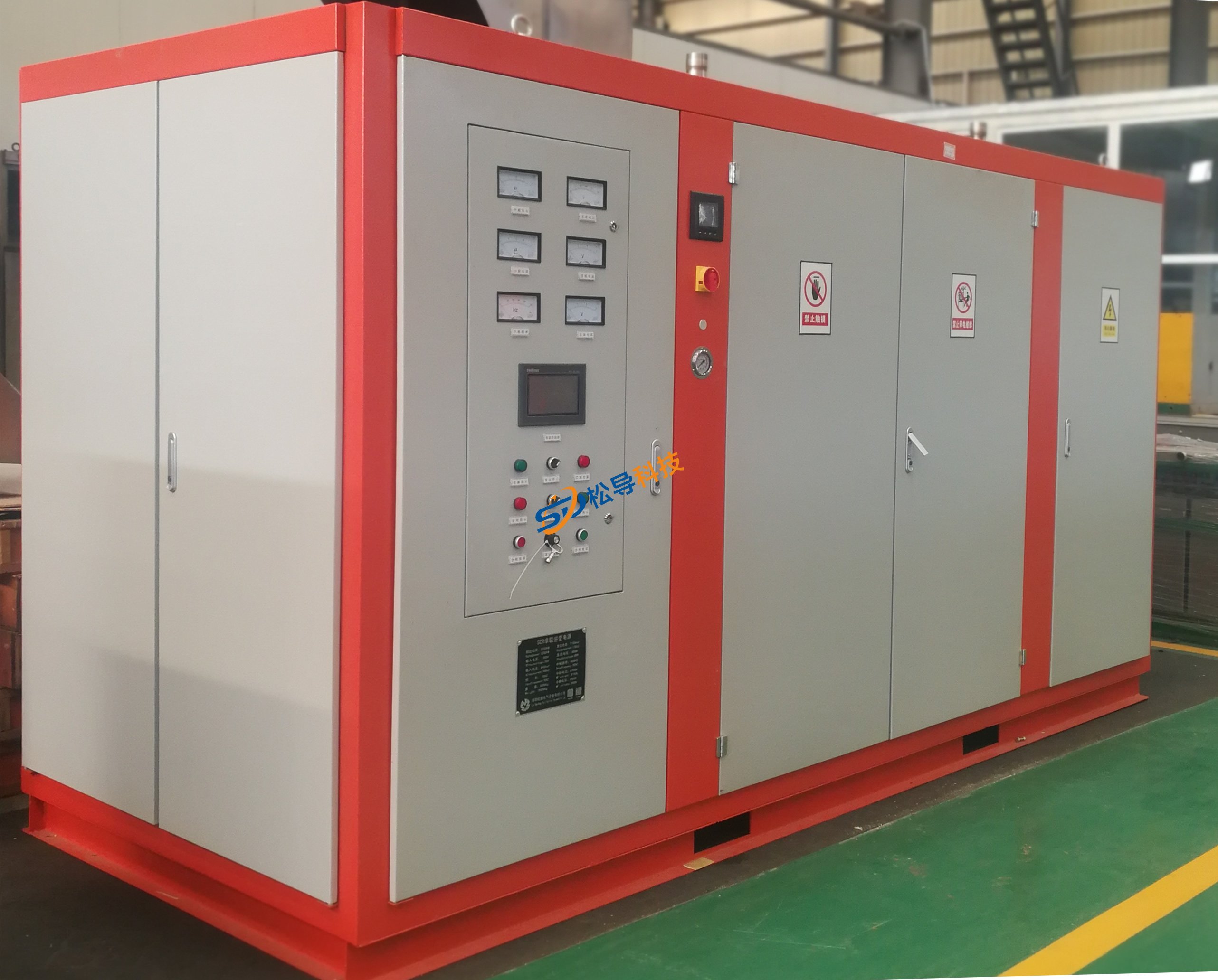
Induction Melting Furnace
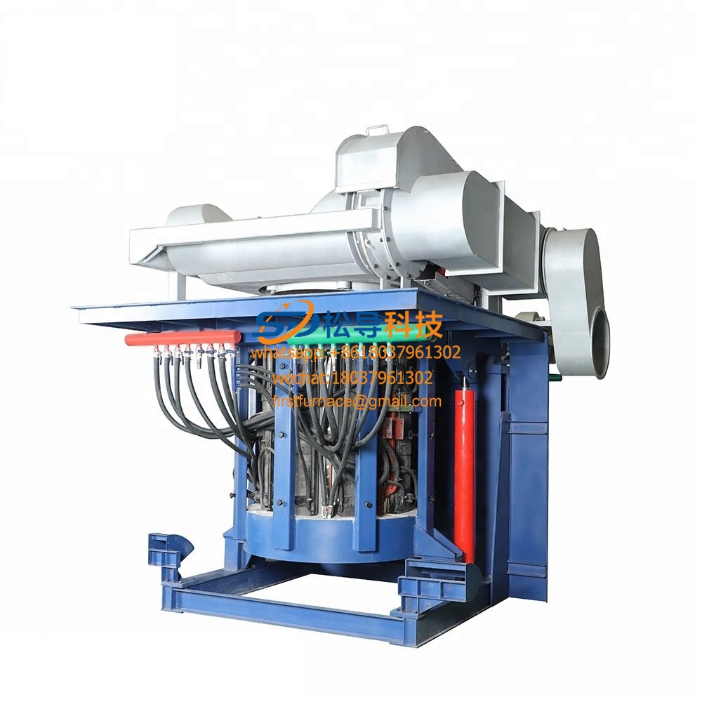
3 T Induction Melting Furnace
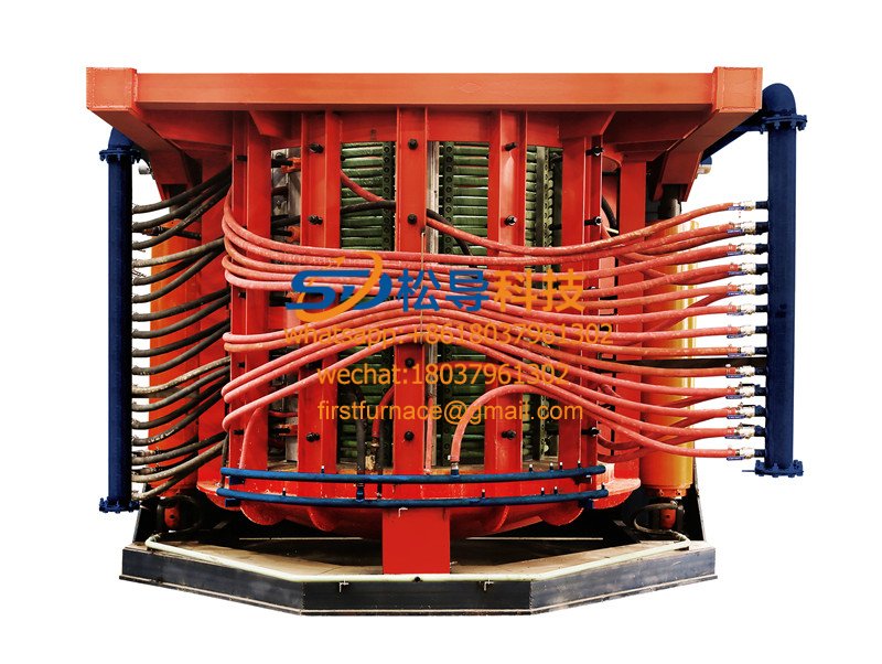
5T Induction Melting Furnace
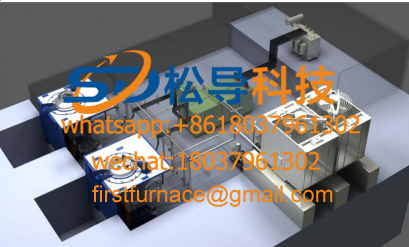
1T One Belt Two Intermediate Frequency F

5T One Belt Two Intermediate Frequency F
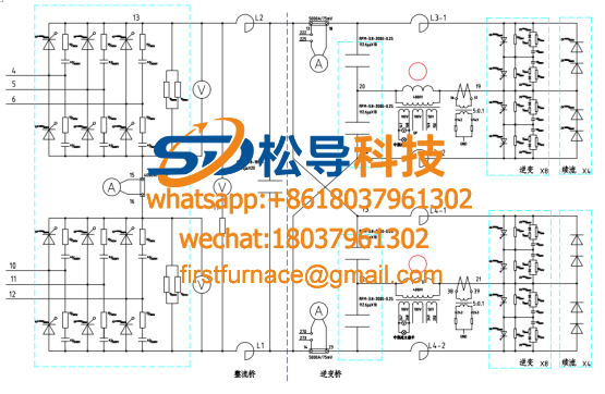
3T One Belt Two Intermediate Frequency F
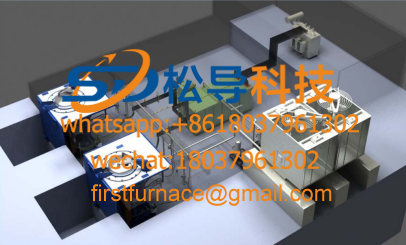
2T One Belt Two Intermediate Frequency F
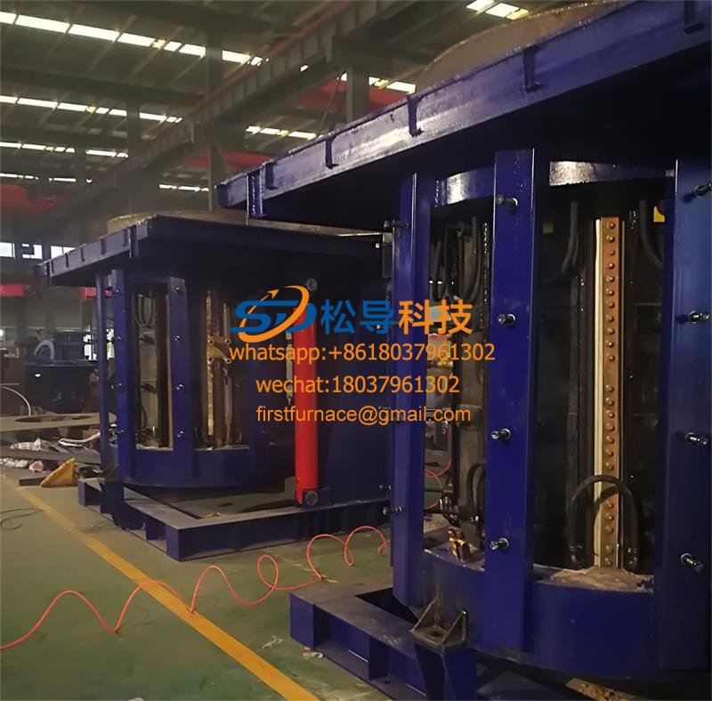
5T Parallel Intermediate Frequency Furna
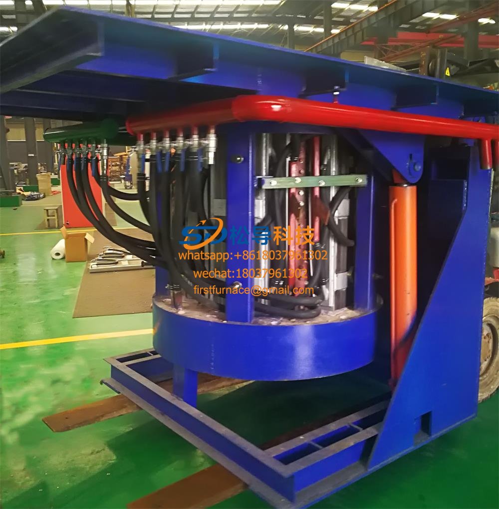
5T Intermediate Frequency Furnace

5T Series Intermediate Frequency Furnace
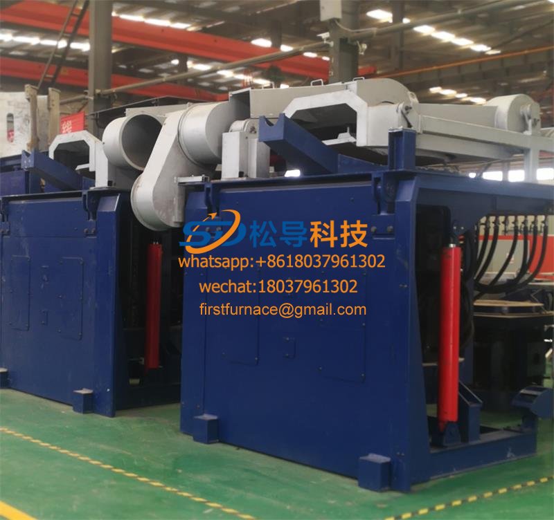
3T Series Intermediate Frequency Furnace
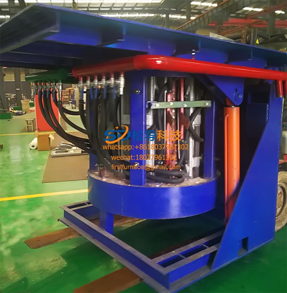
2T Series Intermediate Frequency Furnace
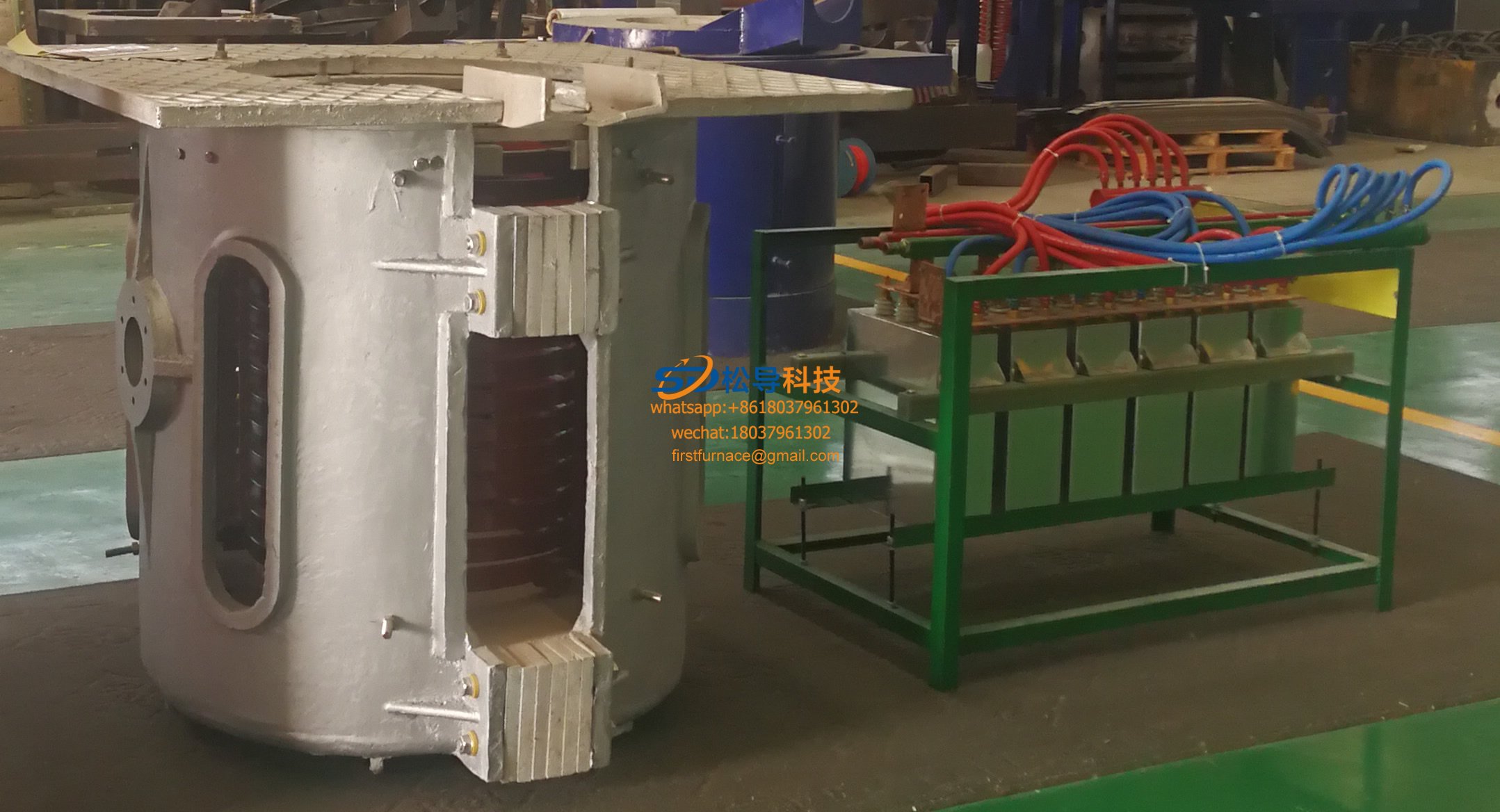
1T Series Intermediate Frequency Furnace
0.5T Series Intermediate Frequency Furna

0.25T Series Intermediate Frequency Furn
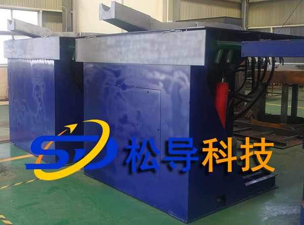
1T Parallel Intermediate Frequency Furna
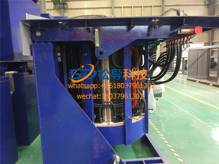
2T Parallel Intermediate Frequency Furna
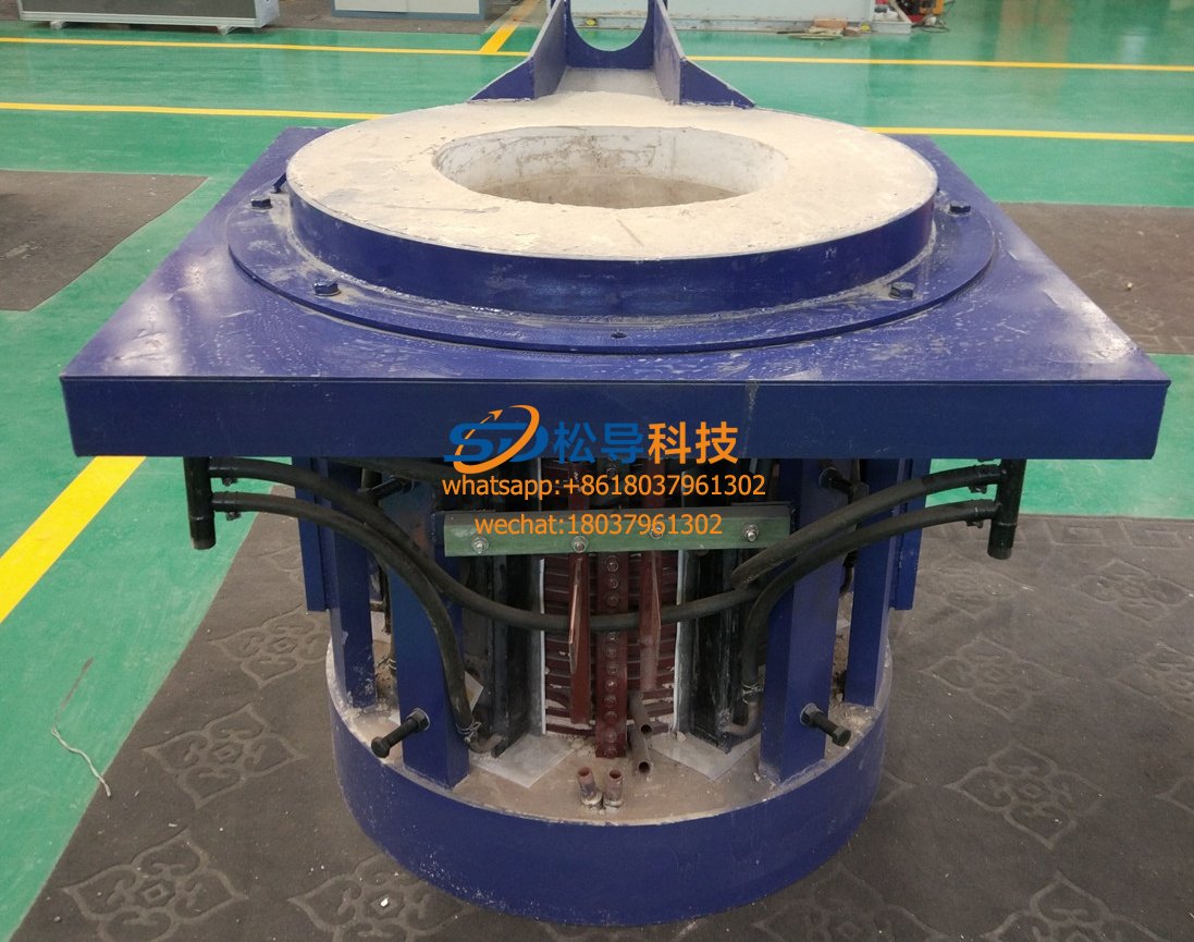
0.5T Parallel Intermediate Frequency Fur


