Sales hot line ( 24 hours service):+86 13015583380
E-Mail: firstfurnace@gmail.com
whatsapp:+86 13015583380
Adress: Luoxin Industrial Park, Luoyang, HenanLarge diameter steel pipe quen
Piston rod quenching and tempe
Grinding rod quenching and tem
High frequency induction heate
Quenching equipment for machin
Round steel end heating furnac
Steel pipe heat treatment prod
Square steel quenching and tem
Sucker rod quenching and tempe
Thickened petroleum steel pipe
Round steel quenching and temp
Steel pipe quenching and tempe
Steel plate quenching and temp
Induction Hardening Machine&nb
Flywheel ring gear high freque
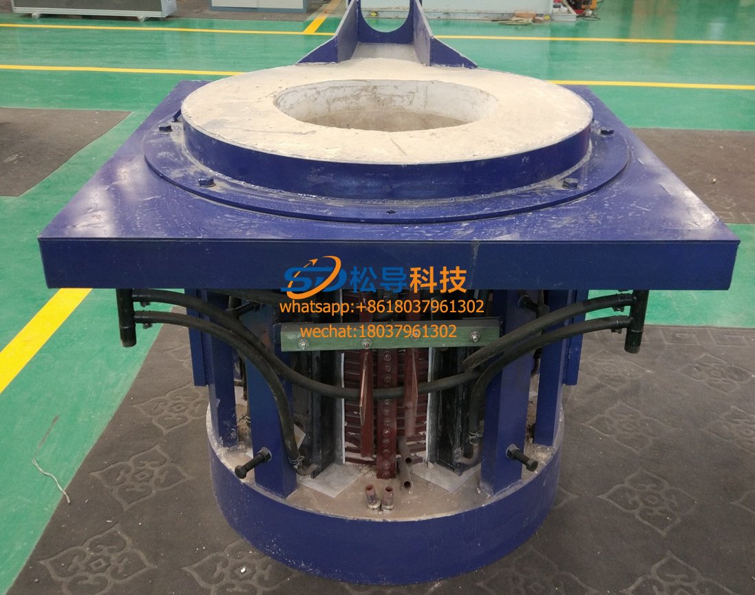
Analysis and explanation of the beauty point of 0.5 ton molten iron furnace
1. Overview:
0.5 tons of a cupola tandem system for the production of cast steel, cast iron, by a set of no less than 400KW variable frequency power supply 1 and the station 0.5t steel coreless induction melting furnace and the secondary system is operating normally required Equipment composition.
2. Working mode of 0.5 ton tandem melting furnace :
A set of furnace smelting production, single furnace melting power 400kw
3. Main process parameters of 0.5 ton tandem melting furnace :
|
Serial number |
model name |
0.5 tons of main parameters |
|
1 |
Transformer rated power |
≥400KVA |
|
1 |
Line voltage |
380V±5% |
|
2 |
Power rating |
≥400KW (a power supply system) |
|
3 |
IF frequency |
≥1000HZ |
|
4 |
Melting temperature |
1600 ° C |
|
5 |
Rated Capacity |
0.5t |
|
6 |
Maximum capacity |
≥0.6t |
|
7 |
Rectification, inverter form |
12-pulse rectifier series inverter |
|
8 |
Melting rate (steel steel) |
0.6t/h |
|
9 |
Melting power consumption (hot furnace, molten steel) |
350KW.h/t±5% (1600°C) |
|
10 |
Melting power consumption (hot furnace, hot metal) |
320KW.h/t±5% (1500°C) |
|
11 |
Power factor |
≥0.95 |
|
12 |
Power supply form |
Single power supply |
|
13 |
Furnace type |
One for one, one set, one rectifier, one inverter, one furnace |
|
14 |
noise |
85dB |
|
15 |
Starting success rate |
100% |
4, Furnace furnace project complete configuration
|
0.5 tons a tandem configuration sets cupola |
||||
|
Serial number |
Name |
Model and notes |
Quantity |
price |
|
1 |
Medium frequency power supply (1 set of rectifier cabinet) (a set of inverter cabinets) |
Single machine design power 400KW |
1 set |
|
|
2 |
Resonant capacitor bank |
Included in the inverter cabinet |
1 set |
|
|
3 |
Leakage alarm device ( optional ) |
|
1 set |
|
|
4 |
Furnace steel shell (including: oil cylinder, iron core, bracket, induction coil, etc.) |
0.5T melting furnace body |
1 set |
|
|
5 |
Model |
|
1 |
|
|
6 |
Water cooled cable |
Water-cooled cable side outlet |
1 set |
|
|
7 |
Hydraulic station system |
|
1 set |
|
|
8 |
Tilting console |
|
1 set |
|
|
total |
|
|||
4.3, 0.5 ton tandem melting furnace main components supporting manufacturers (for famous manufacturers)
|
1.Power cabinet: |
(1) Main breaker |
Shanghai People's Electric Appliance Factory or Delixi DW Series |
|
|
(2) Rectifier thyristor |
Hubei Xiangfan Power Electronics Group Co., Ltd. |
|
|
(3) Inverter thyristor |
Hubei Xiangfan Power Electronics Group Co., Ltd. |
|
|
(4) Main control board |
Famous furnace mall |
|
|
(5)Buttons, indicators, etc. |
Shanghai Electric Appliance Factory |
|
|
(6) Protecting the thyristor's resistance and capacitance |
794 factory and 795 factory |
|
|
(7) Copper |
Zhejiang Shangyu Copper Material Factory |
|
2.Capacitor |
|
Xinweijiang Capacitor Factory "Weiwei" brand |
|
3. Stove |
(1)Induction coil copper tube |
Luoyang Copper or Zhejiang Shangyu Copper Material Factory |
|
|
(2) Silicon steel sheet |
Wuhan Iron and Steel Company |
|
|
(3) Hydraulic cylinder |
Shanxi Yuci Group |
|
4. Hydraulic system |
(1) Hydraulic components |
Shanxi Yuci Group Hydraulic Factory |
|
|
(2) Oil pump |
Shanxi Yuci Group Hydraulic Factory |
|
|
(3) Motor |
Xi'an or Kaifeng Motor Factory |
5, 0.5 tons of tandem melting furnace main equipment functions, processes and technical description
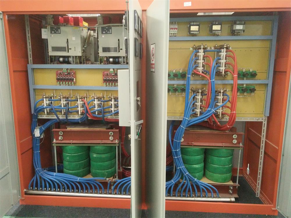
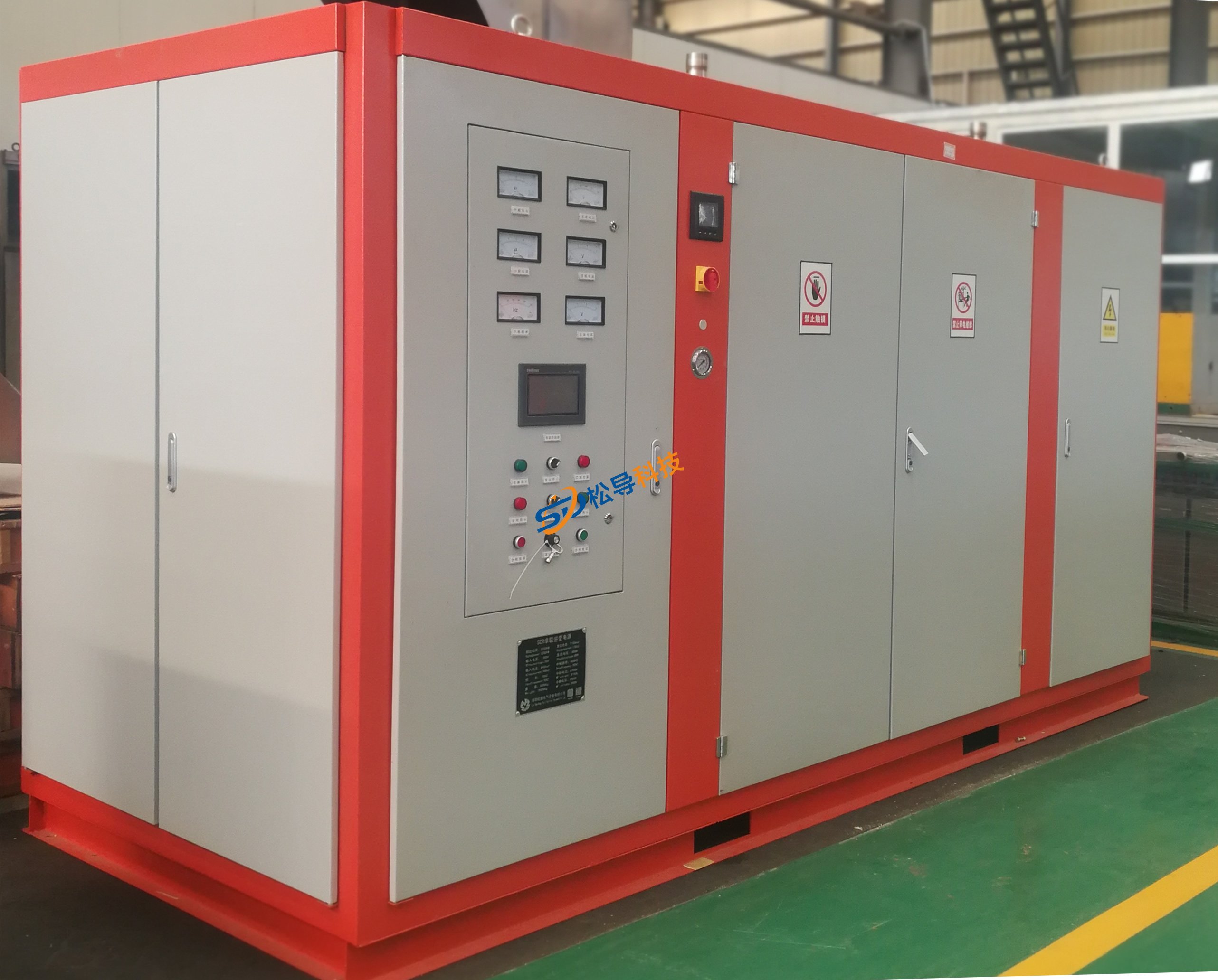
5.1, power cabinet: (a rectifier cabinet and a inverter cabinet)
The series resonant dual output IF power supply is housed in a closed cabinet. The incoming power supply is 380V, 3-phase (12 pulses), 50HZ.
5.2, cabinet
Cabinet body is made of cold rolled steel sheet is not less than 1.5 mm thick high strength. Opening the door makes it easy to access parts such as rectification and inverter. There are hooks on the top of the power cabinet for easy transportation and installation.
The components of the power cabinet are reasonably arranged, easy to maintain, and the wiring and wiring are in compliance with the specifications. It is convenient for maintenance personnel to easily access all maintenance points.
The copper bars are all set to reasonable water cooling as needed.
5.3, isolation control room
A closed isolation control room is arranged at the upper part of the front door, and control components such as a main control board, a feedback board, and a control power supply are provided, so that the signal of the main control board can be conveniently observed.
The isolation control room does not require additional cooling.
5.3, the power receiving part
The secondary side of the circuit breaker receiving rectifier transformer is powered by busbar or copper bus, and the circuit breaker is Delixi DW15. They are equipped with a manual switch and an undervoltage coil for interlock protection. It consists of a circuit breaker, a voltage transformer, a current transformer, and the like.
5.4, the rectification part
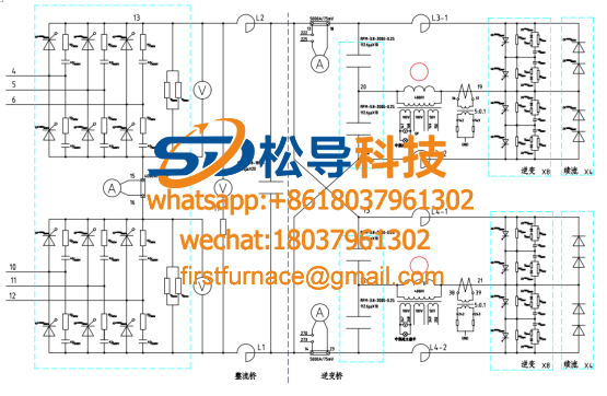
Voltage feedback series type; the circuit adopts 12-pulse circuit rectification mode, the incoming line voltage is 380V, and the rectifier part of the thyristor adopts the latest stacked heat sink assembly.
The RC absorption branch at both ends of the thyristor can act as a buffer current sudden change when the thyristor switch is used.
5.5, filter network
Reactor, leveling DC current, removing current ripple and preventing high frequency signals from entering the factory power supply line.
Filter capacitor . Filter capacitor is water cooled
The filter capacitor has an external discharge resistor that can be discharged within 5 minutes after the power is turned off.
The reactor is air-core, water-cooled, vacuum-cast with epoxy resin, and sealed.
5.6, molten iron furnace inverter part
The inverter circuit has a series resonant inverter bridge, which has a buffering function when the thyristor switch is connected in parallel with the thyristor switch at both ends of the thyristor.
1. Constant power output, power output adopts constant control. During the melting process, when the load and temperature change, the load is always full power output, thus shortening the melting time.
2. High power factor ensures that the power factor is not less than 95% at any power.
3. The starting characteristics are good. Under full load and heavy load conditions, it can be started at will, and the starting success rate is 100%.
5.7 control system
1. Equipped with output voltage meter, output power meter, working frequency meter, input current meter, input voltmeter, DC voltmeter, DC current meter, phase display on the control panel, and inverter working display.
2. The circuit board contains all the necessary control and electronic logic components to respond instantaneously to the voltage, current and power of each induction coil and to generate a thyristor trigger pulse.
3. The circuit board sets limits on the inverter to avoid damage to the thyristors and capacitors in the event of current or overvoltage.
4. The circuit board ensures the reliability of the system; and a comprehensive monitoring of the system is performed for each half cycle of the furnace current.
5. Press the button to control the “Run” and “Disconnect” of the inverter.
6. The main power indicator light, when the circuit breaker is closed to send power to the variable frequency power supply, this indicator lights.
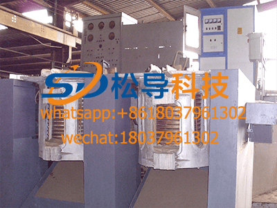
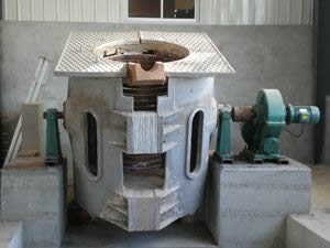
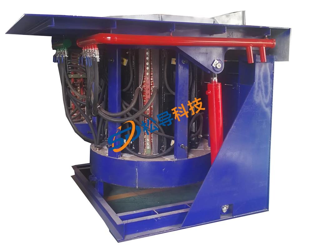
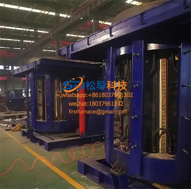
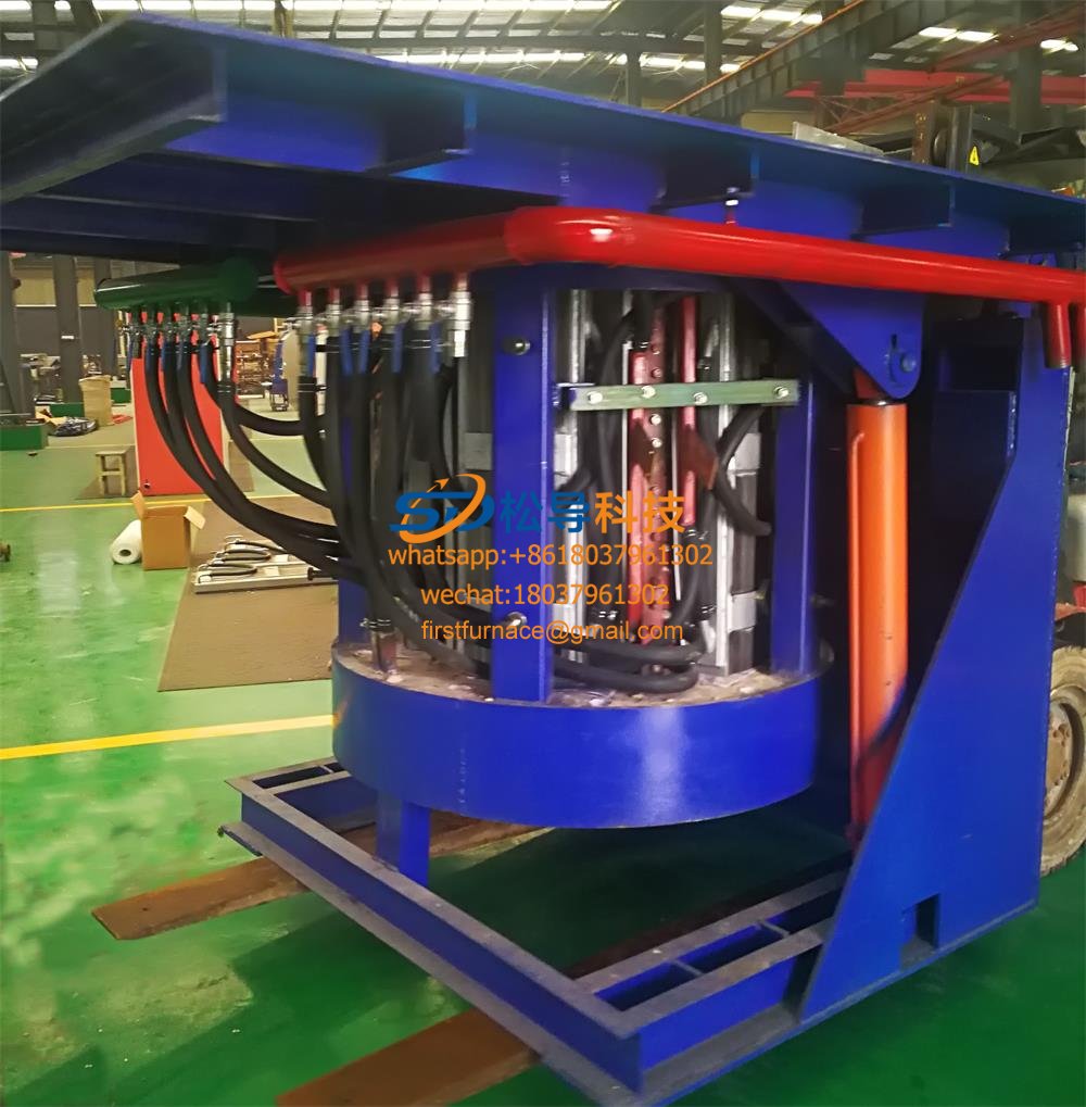
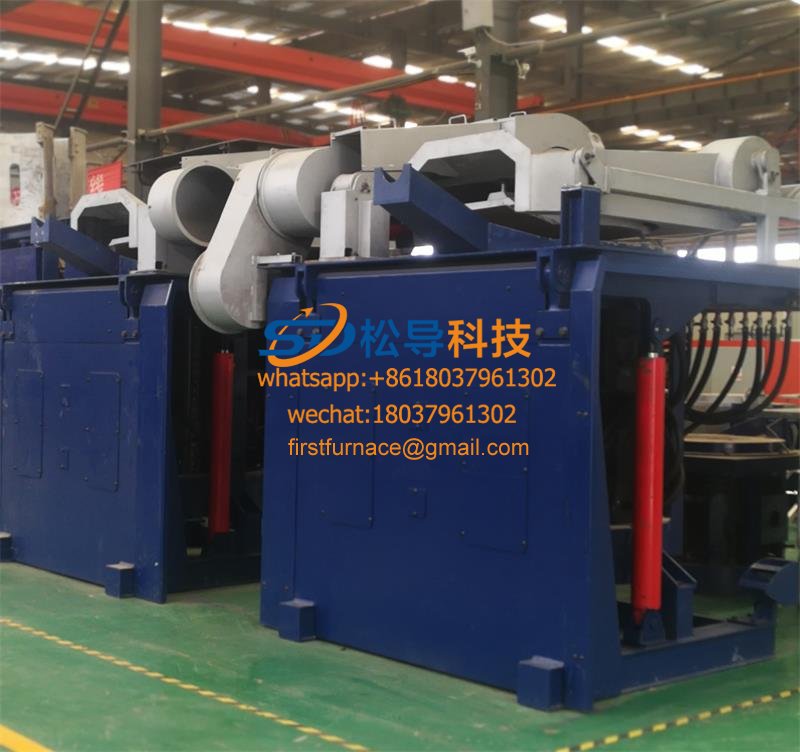
5.8, 0.5 ton tandem melting furnace body ( 1 set):
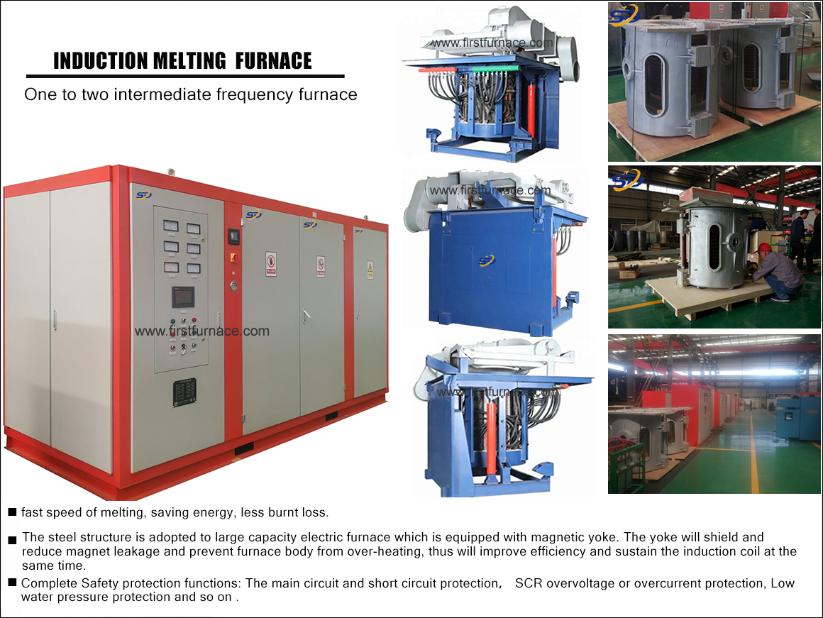
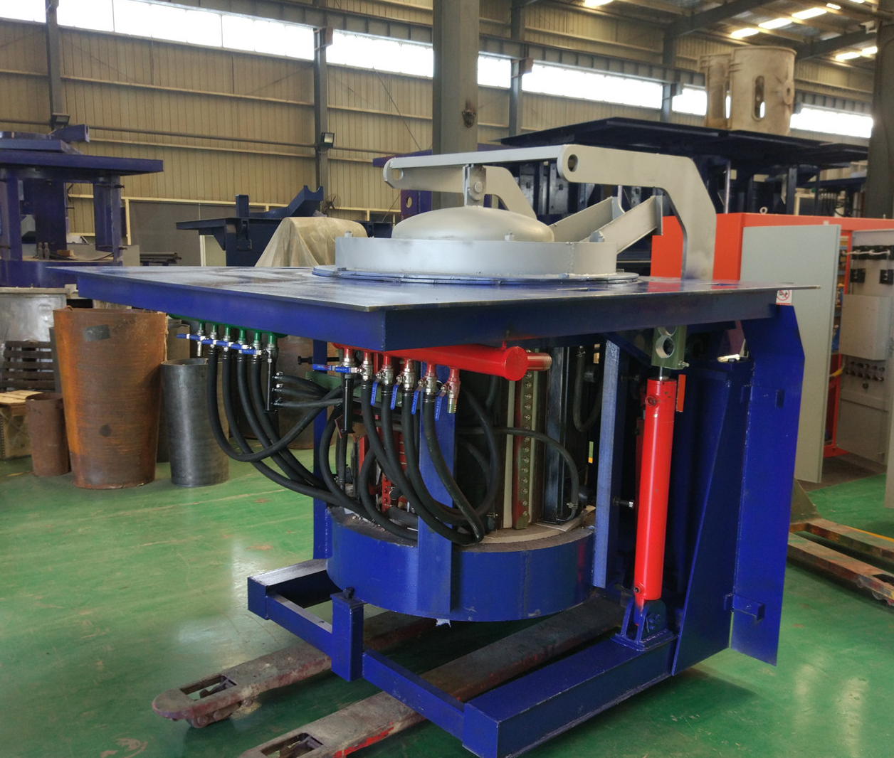
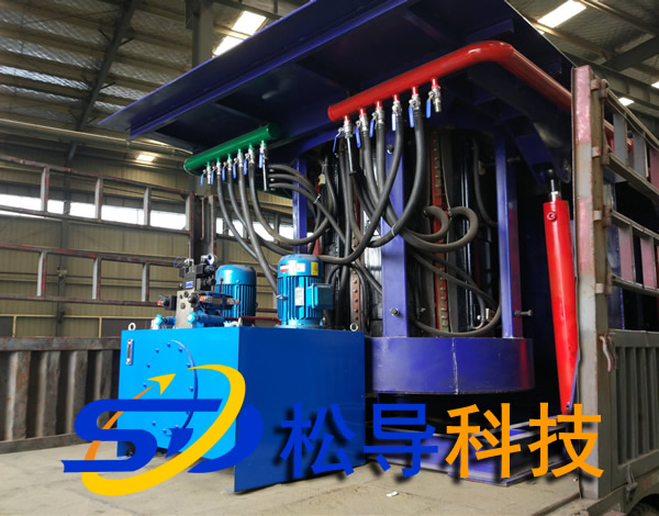
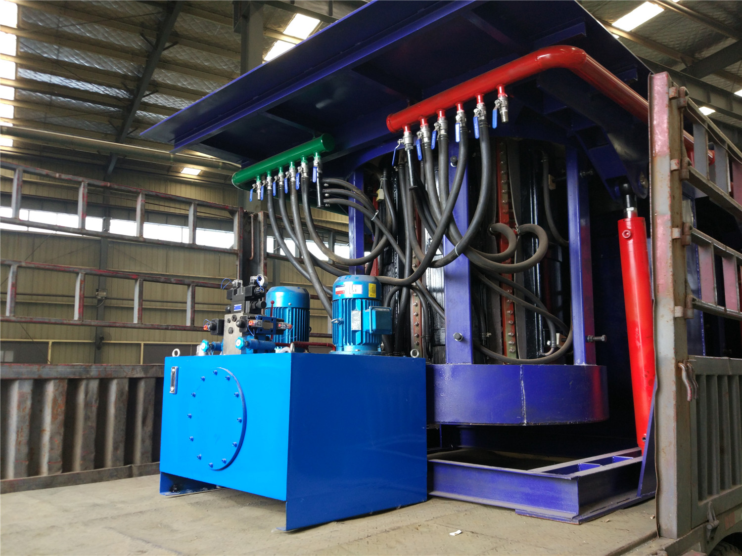
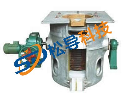
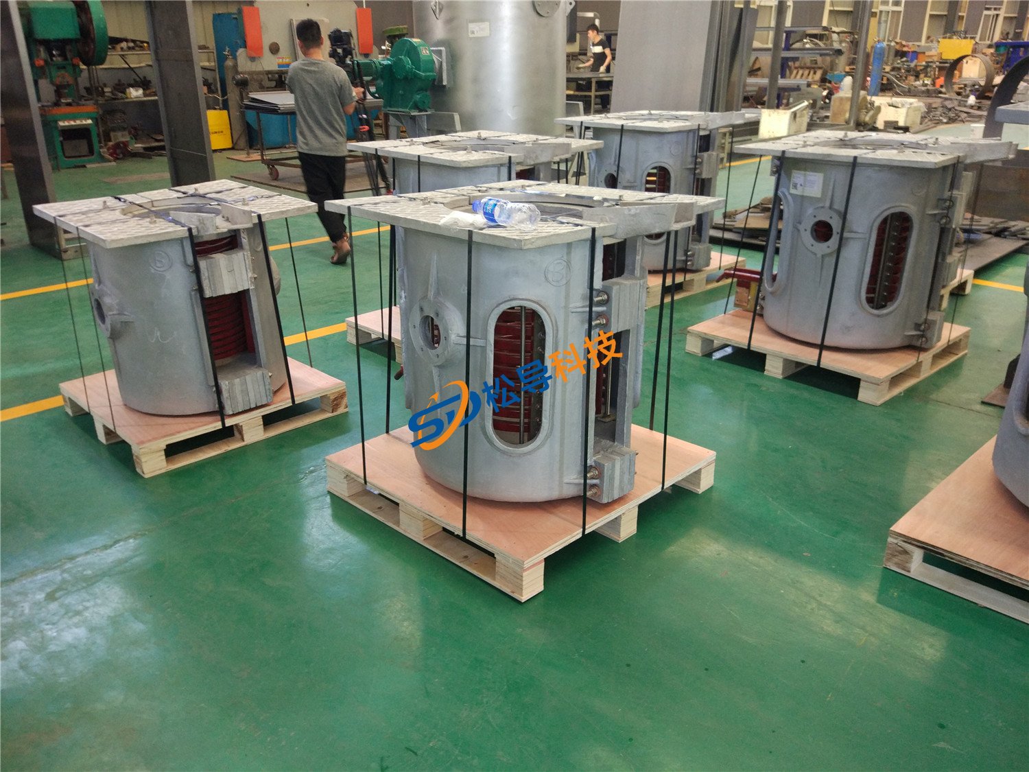
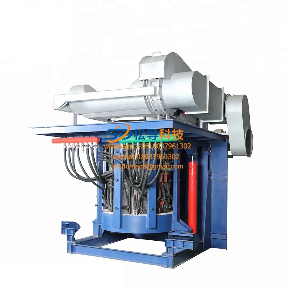
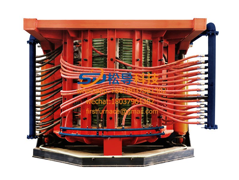
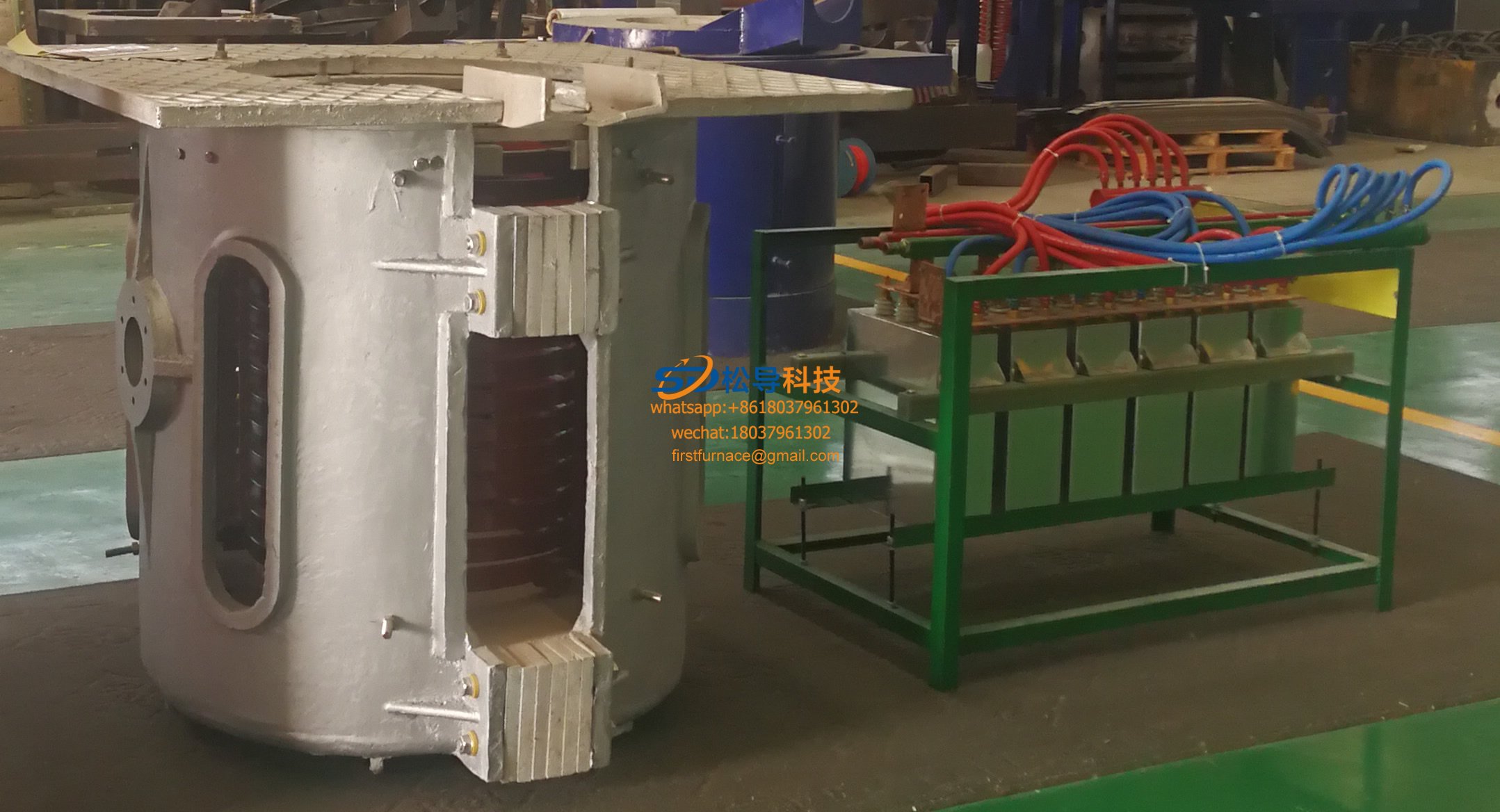
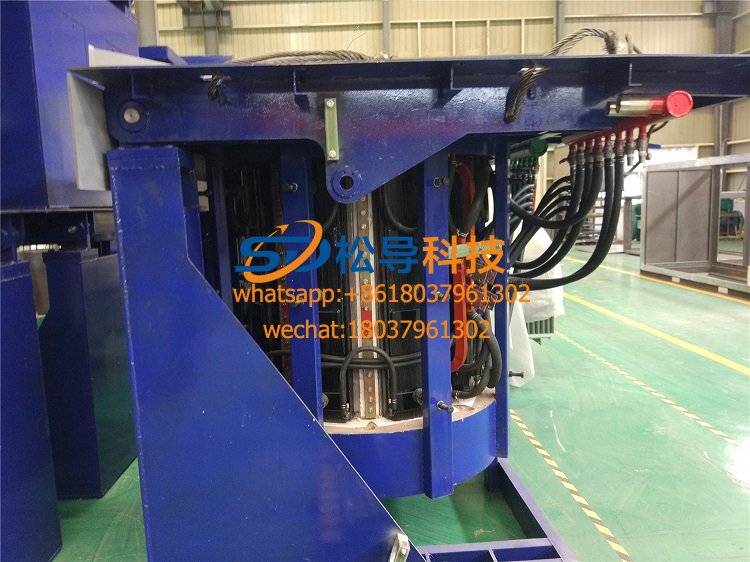
The furnace body is composed of a furnace shell, a fixed frame, a tilting furnace mechanism, an induction coil, a yoke, etc., and is additionally provided with a furnace lining material and a leaking furnace alarm device.
5.8.1, furnace shell:
The medium frequency melting furnace shell is a squirrel-cage frame structure welded by steel plate, and the lower part of the furnace shell has a fixing bracket of the furnace lining mechanism. A contour yoke is provided in the furnace shell. The yoke shielding can reduce the leakage magnetic flux to prevent the furnace body from heating, improve the electric energy efficiency, support the induction coil at the same time, improve the strength, and can conveniently disassemble the coil and repair, observe and dissipate the coil when the yoke is not taken away.
5.8.2, fixed frame:
The fixed hob adopts high-strength integral steel structural parts to ensure long-term work without deformation. The furnace platform is made of 10mm pattern steel plate, which can be kept flat and not deformed during long-term use, and the noise on the working platform of the furnace is <85dB.
5.8.3, tilting mechanism (hydraulic plunger cylinder)
The tilting furnace adopts two inverted plunger hydraulic cylinders, and the hydraulic cylinder inlet port is directly connected to the speed limiting shut-off valve (flow control valve) to prevent the furnace body from falling sharply due to the rupture of the pipeline and the like, causing an accident. Manual speed control reversing valve control.
The two oil cylinders are connected in parallel, and there is no jamming at the same time. The furnace body rises and falls smoothly when the furnace is tilted. A high temperature resistant protective sleeve is required on the outside of the cylinder.
5.8.4, induction coil (ie sensor)
The induction coil is made of TU1 type (purity of 99.97% electrolytic copper), wall thickness / 6mm extruded rectangular copper tube on a special mold, the pitch error is not more than 2mm, and the coil group needs to be relieved after welding. deal with.
The induction coil is made of high temperature resistant, high pressure insulation paint, which is dip coated and vacuum dried. The insulation grade is H grade. The induction coil passed the 12kg/cm3 water pressure withstand test before leaving the factory.
A stainless steel water-cooling ring is arranged on the upper and lower parts of the induction coil to ensure uniform heating of the furnace lining. A Faraday short-circuit ring is required at the upper and lower ends of the coil to fully absorb the leakage flux at the upper and lower ends to prevent the furnace body from heating up. The furnace body is connected to a large-section water-cooled cable, and the lead-out line is in the form of a side lead-out line.The coil pressing device is pulled down on the stainless steel rod.
5.8.5, yoke
The yoke is laminated with Z11 high-quality crystal oriented cold-rolled silicon steel sheet, and its thickness is ≤0.3mm, which is clamped on both sides with stainless steel. The yoke has a contoured arc-shaped structure that is consistent with the outer diameter of the coil. After assembly, the bending degree is ≤ 4mm, and the deviation between the theoretical center line and the actual center line is ≤ 3mm. The yoke covers the area of the induction coil ≥60%. The yoke fixing method: the yoke is closely attached to the induction coil, and a high-voltage insulating layer is used in the middle, and the outer surface is screwed on the stainless steel plate on the back of the yoke.
The inside of the yoke stainless steel clamping plate needs a water-cooled radiator. When the electric furnace is in operation, the yoke temperature is kept at normal temperature to prevent the yoke temperature from rising and deformation, thereby strengthening the support of the induction coil and improving the strength of the furnace body.
5.8.6, 0.5 ton tandem molten iron furnace leak alarm device
It is necessary to set the lining thickness detecting device: when the lining thickness detecting device is working normally, the work indicator lights up and the warning light goes out. When the furnace lining has a low resistance phenomenon or the induction coil has a short circuit to the ground, the alarm lamp lights up and the buzzer sounds an alarm.
The detection device has a self-test button and a reset button. When the device is normal, the self-test button is pressed, the alarm lamp is lit, and the buzzer alarms. Press the reset button to cancel the alarm and resume the detection device to work again. The button below the reset button and the self-test button is used to break the bottom electrode. When the detecting device is in normal operation, the button can be used to initially determine the cause of the alarm. The detecting device can judge the change of the lining.
5.8.7. Output copper bars and water-cooled cables
The output copper row is made of high quality T2 copper bars with a purity of 99.9%. The copper busbar is connected to the variable frequency power supply and the furnace water-cooled cable.
The water-cooled cable is made of high-quality T2 material multi-strand copper stranded wire. The jacket is made of American Gates carbon-free hose or high-strength flame-retardant rubber tube. The joint needs to be cold-formed to ensure good contact and strong tensile strength.
The water-cooled cable and the induction coil must be connected to ensure better electrical conductivity, no deformation under high temperature working environment, good contact, long service life, impermeability > 10kg/cm 2 , convenient and quick to replace, easy to repair.
5.8.9, model
The boring die is made of ≥8mm steel plate and can be pulled out at any time as the furnace melts or the slab is finished.
5.9, 0.5 ton tandem molten iron furnace hydraulic device
The hydraulic device is mainly composed of two parts: a hydraulic pump station and a hydraulic console.
5.10, hydraulic pump station
The hydraulic pumping station is used to power the tilting cylinder, and has a pressure regulating device, a return oil and an oil suction filtering device. The hydraulic cylinder requires a protective cover to ensure that the cylinder rod is not contaminated by dust and splash metal.
5.11, hydraulic console
The hydraulic console is mounted on the table to control the tilting of the furnace (in the range of 0 to 95 degrees) and the lining. The operation console is operated by manual hydraulic valve. The work should be reliable, stable, without impact and creeping. The speed can be adjusted and can stay at any position.
Author: Kang Zhongbo
Iron induction furnace
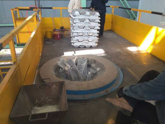
Aluminum melting furnace
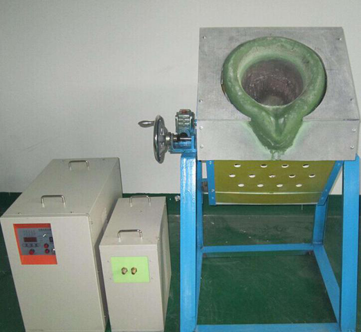
Copper melting furnace
Small steel melting furnace
Small induction melting furnace
Induction iron furnace
3T intermediate frequency iron melting f
0.25T Intermediate Frequency Furnace
0.5T Intermediate Frequency Furnace
Medium Frequency Furnace

2T Induction Melting Furnace
1T Induction Melting Furnace
500kg Induction Melting Furnace
250kg Induction Melting Furnace
Induction Melting Furnace
3 T Induction Melting Furnace
5T Induction Melting Furnace
1T One Belt Two Intermediate Frequency F

5T One Belt Two Intermediate Frequency F
3T One Belt Two Intermediate Frequency F
2T One Belt Two Intermediate Frequency F
5T Parallel Intermediate Frequency Furna
5T Intermediate Frequency Furnace

5T Series Intermediate Frequency Furnace
3T Series Intermediate Frequency Furnace
2T Series Intermediate Frequency Furnace
1T Series Intermediate Frequency Furnace
0.5T Series Intermediate Frequency Furna

0.25T Series Intermediate Frequency Furn
1T Parallel Intermediate Frequency Furna
2T Parallel Intermediate Frequency Furna
0.5T Parallel Intermediate Frequency Fur


