Sales hot line ( 24 hours service):+86 13015583380
E-Mail: firstfurnace@gmail.com
whatsapp:+86 13015583380
Adress: Luoxin Industrial Park, Luoyang, HenanLarge diameter steel pipe quen
Piston rod quenching and tempe
Grinding rod quenching and tem
High frequency induction heate
Quenching equipment for machin
Round steel end heating furnac
Steel pipe heat treatment prod
Square steel quenching and tem
Sucker rod quenching and tempe
Thickened petroleum steel pipe
Round steel quenching and temp
Steel pipe quenching and tempe
Steel plate quenching and temp
Induction Hardening Machine&nb
Flywheel ring gear high freque
Specific installation method of electric part of induction melting furnace
The installation of the electrical part includes the installation of a high voltage cabinet (or high voltage load switch), a rectifier transformer, a KGPS intermediate frequency power supply cabinet, an RFM compensation capacitor cabinet, and a low voltage power cabinet. Installation must be done in the following order:
The intermediate frequency furnace is in place:
The intermediate frequency furnace should be in accordance with the layout plan provided by the design institute or the manufacturer, and the adjustment level and size should meet the relevant drawing requirements.

Intermediate frequency furnace fixed:
The rectifier transformer should be placed on the base rail accurately and fixed.
After the other electric intermediate frequency furnace is in place, it needs to be watered twice, then hang the anchor bolts, water the cement, and fasten the anchor bolts after the health; if it is not required to be watered twice, fix the anchor bolts at the anchor holes. .
Main electrical connection between intermediate frequency furnaces:
The connection between the high voltage 10KV and the high voltage switchgear (or high voltage load switch) is made of high voltage cable, high voltage cable overhead or along the high voltage cable trench, from the factory high voltage distribution room to the high voltage switchgear (or high voltage load switch); high voltage switchgear The connection between the (or high-voltage load switch) and the rectifier transformer is made of a high-voltage cable or a copper busbar of the same cross-section, and the cable (copper busbar) is to be fixed.
The connection between the rectifier transformer and the KGPS intermediate frequency power supply, the KGPS intermediate frequency power supply cabinet and the RFM compensation capacitor cabinet is an overhead copper busbar, and the copper busbar should be fixed.
The connection between the compensation capacitor cabinet and the water-cooled cable of the furnace body should use the overhead water-cooled copper busbar due to the relatively large current. The distance between the water-cooled copper busbars is “80mm to reduce the influence of the tank inductance on the start of the intermediate frequency power supply; the water-cooled copper busbars are separated by 1500mm. Fix it at a fixed point. The metal part of the fixing bracket should be away from the copper busbar (d>200mm) to reduce the induction heating of the metal body by the intermediate frequency.
The principle of selection of the main electrical connection fastening bolts:
a) The power frequency is 50Hz or the DC part is made of copper bolt (or galvanized steel bolt)
b) Copper bolts are used for the power frequency of 500Hz (non-magnetic stainless steel bolts 1Cr18Ni9Ti)
3.5 Color selection principle of main electrical copper busbar color standard paint:
a) Three-phase power supply A----yellow; B-phase----green; C-phase---red
b) Intermediate frequency power supply----black
9.2.4. Control electrical connection between intermediate frequency furnaces:
9.2.4.1 Distribution cable
a) The connection between the workshop power distribution room and the low-voltage power cabinet adopts three-phase four-wire power cable with a capacity of 30KVA;
b) The low-voltage power cabinet is divided into the electric furnace, the water cooling system and the intermediate frequency power supply using three-phase four-wire cable.
Control Cable
The control cable for electrical signal communication between the intermediate frequency furnaces shall be multi-core control cable, and all control cables shall be buried in the cable trench or placed on the wall through the threading pipe. The threading tubes are fixed by 1 meter apart.
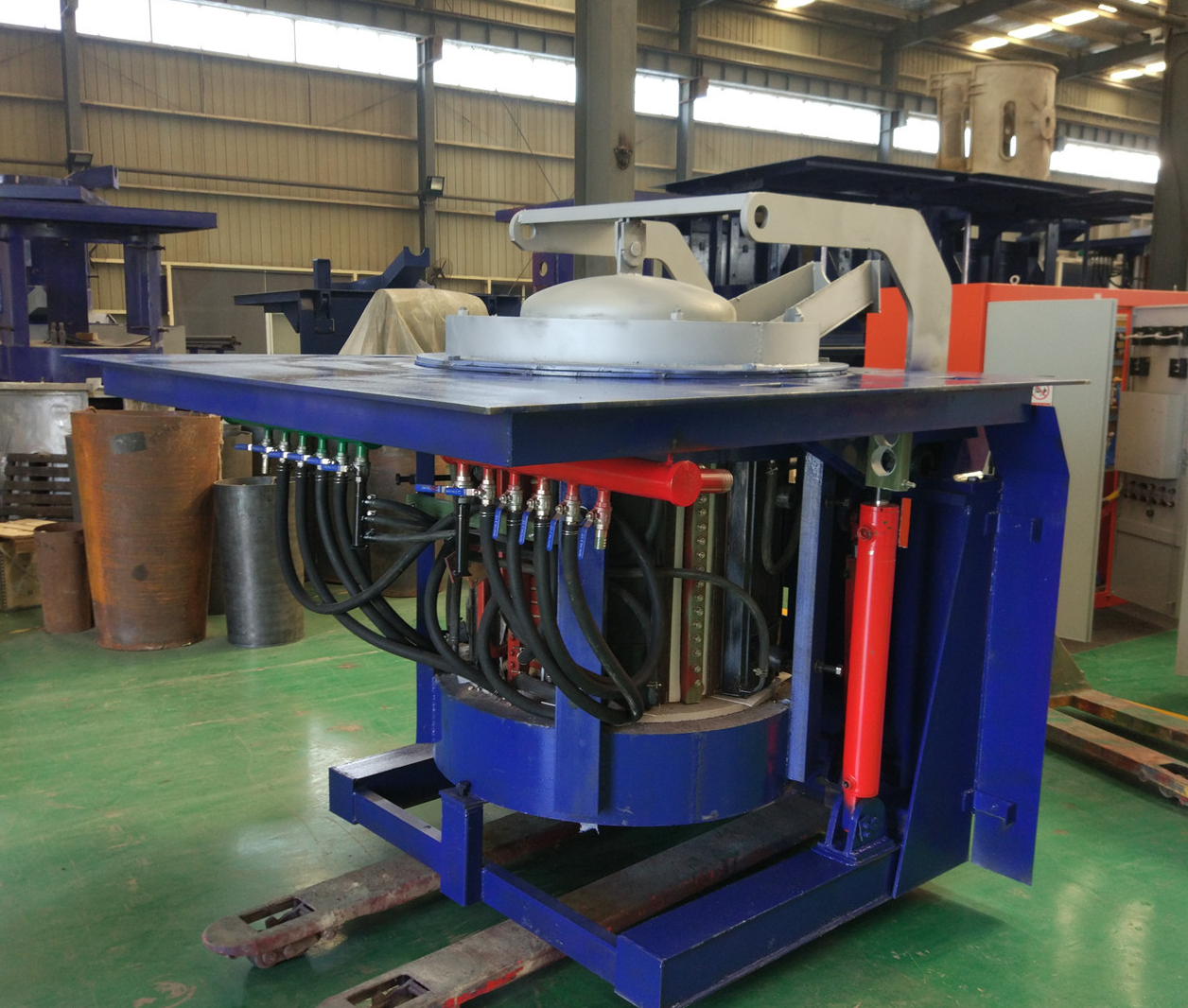
Iron induction furnace
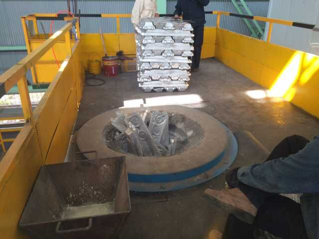
Aluminum melting furnace
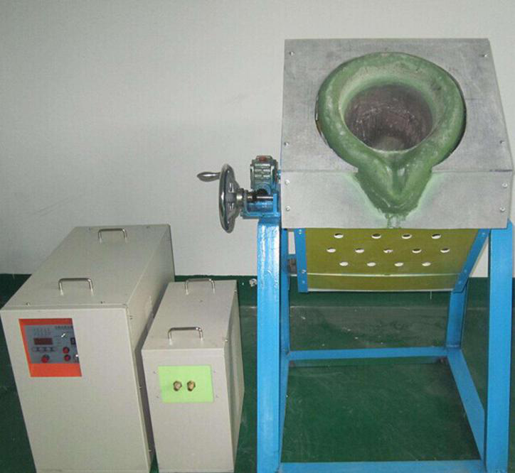
Copper melting furnace
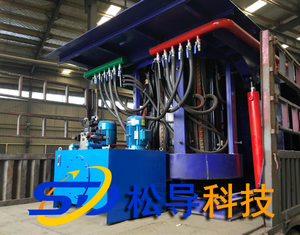
Small steel melting furnace
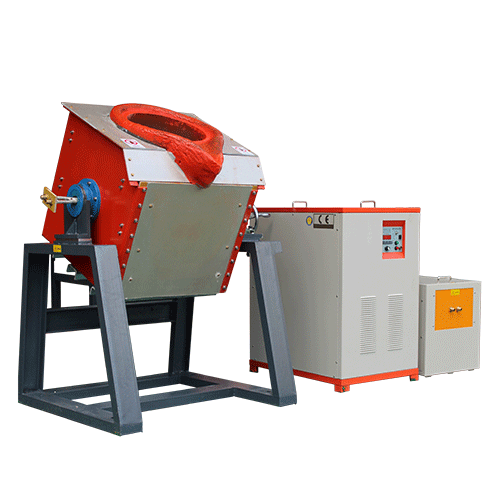
Small induction melting furnace
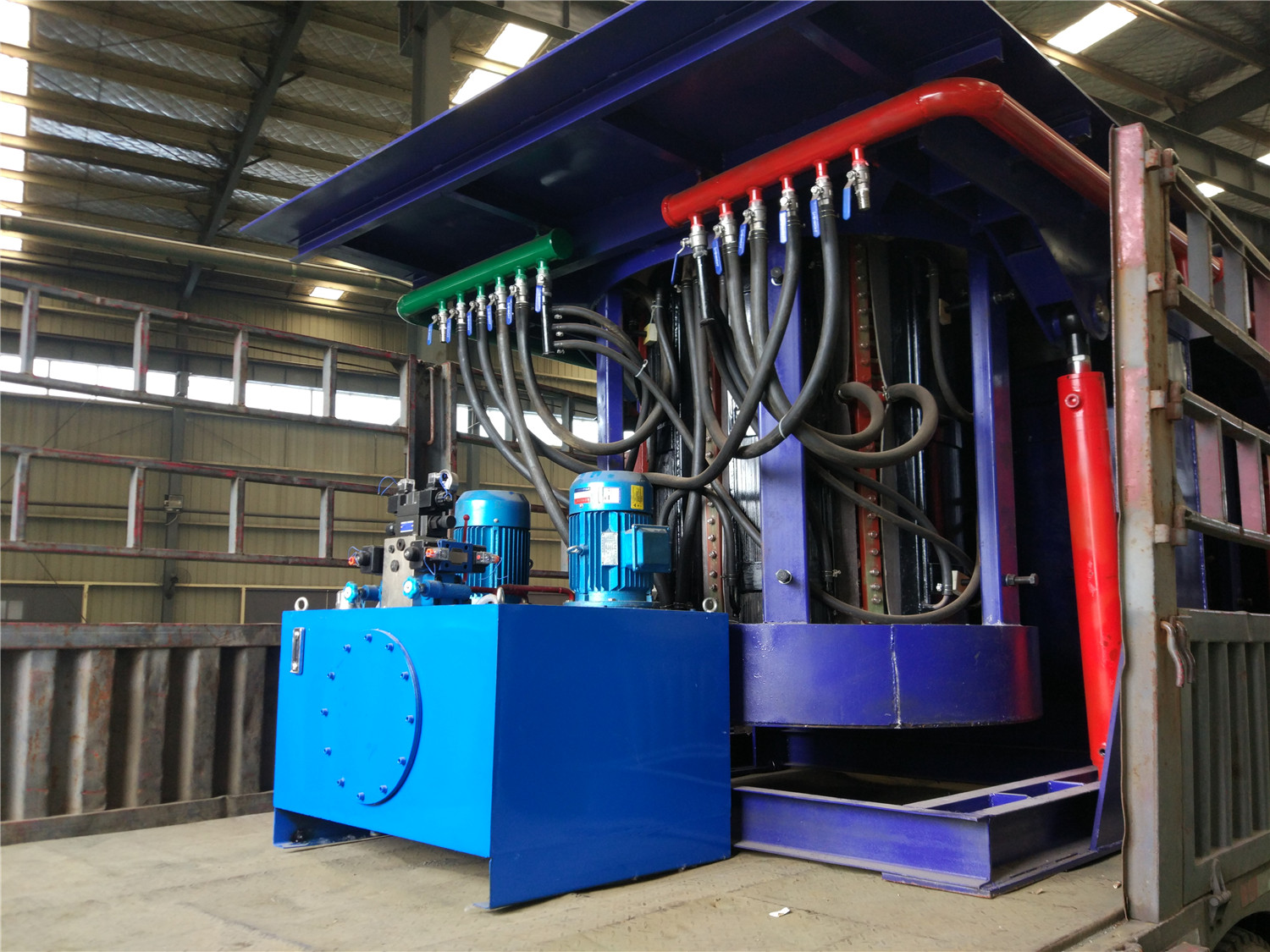
Induction iron furnace
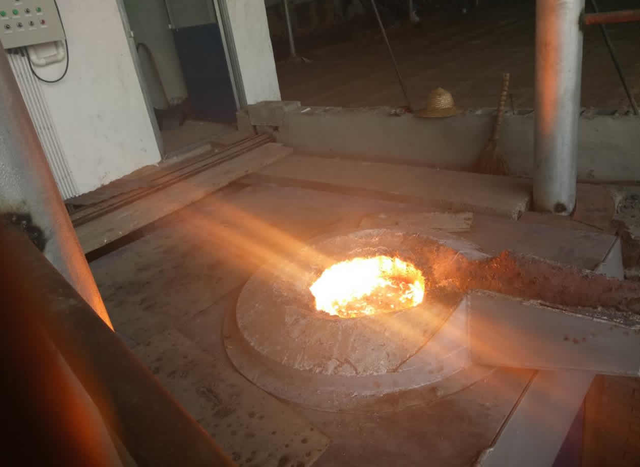
3T intermediate frequency iron melting f
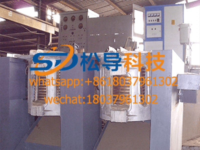
0.25T Intermediate Frequency Furnace
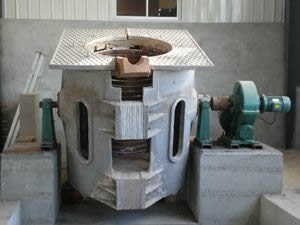
0.5T Intermediate Frequency Furnace
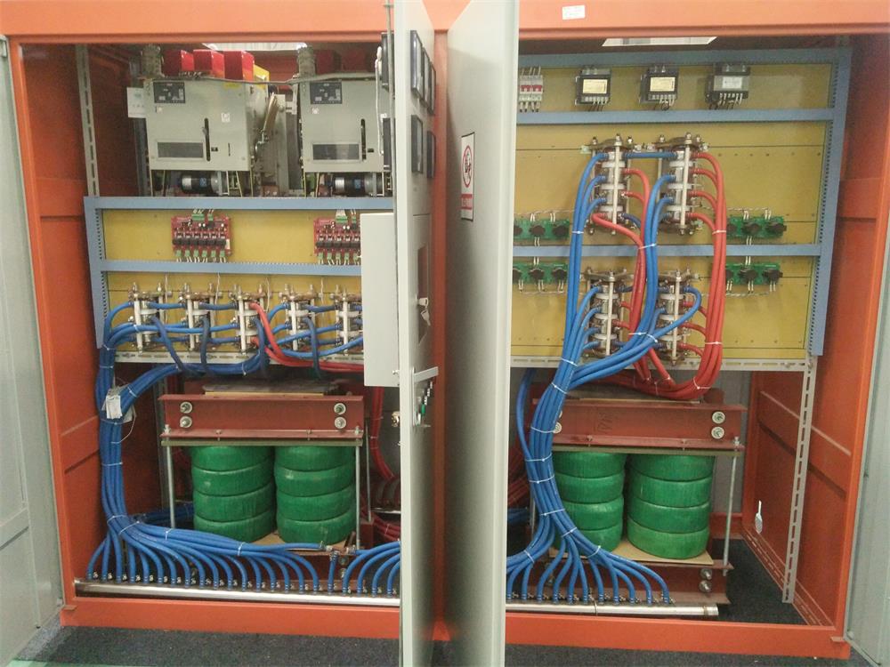
Medium Frequency Furnace

2T Induction Melting Furnace
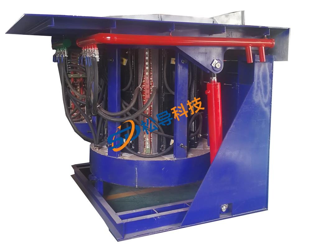
1T Induction Melting Furnace
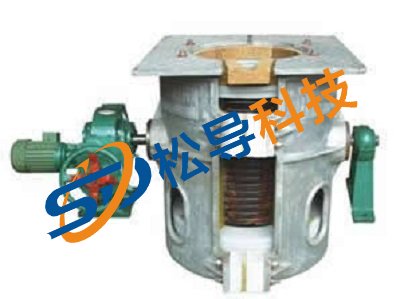
500kg Induction Melting Furnace
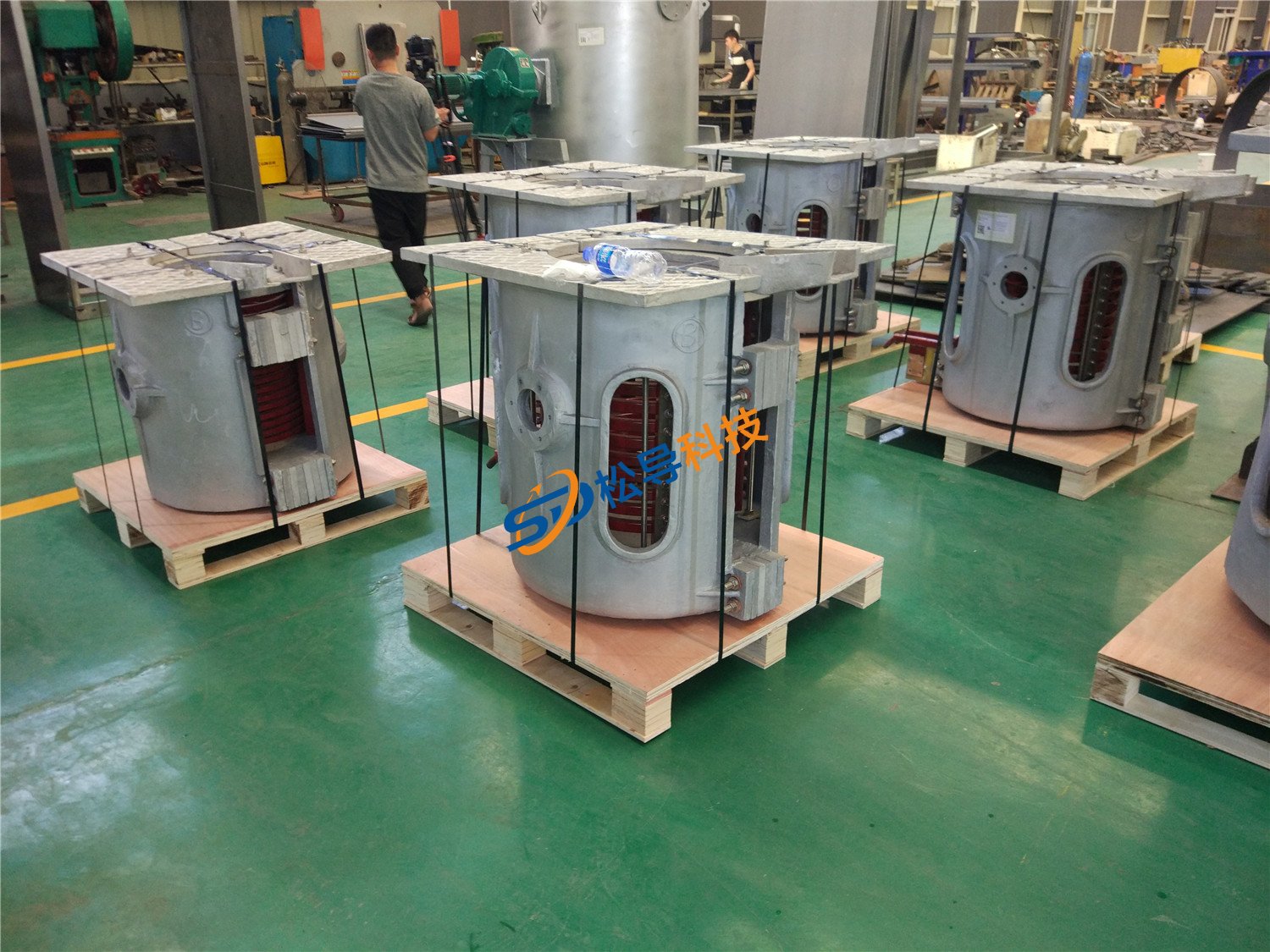
250kg Induction Melting Furnace
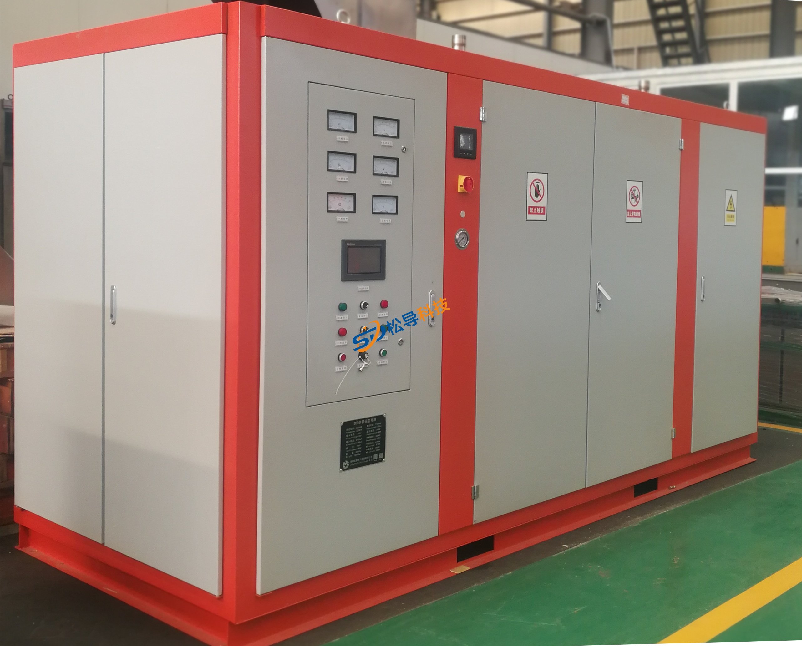
Induction Melting Furnace
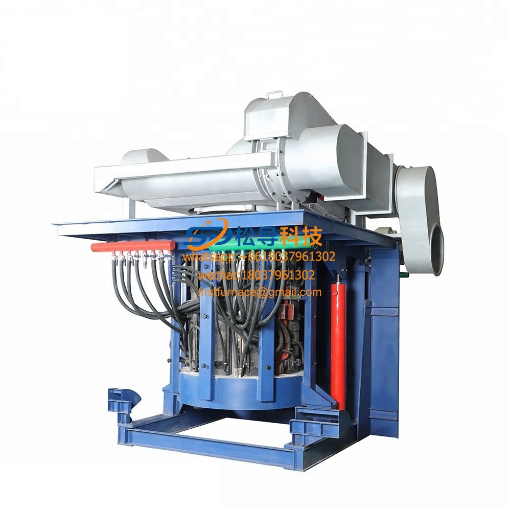
3 T Induction Melting Furnace
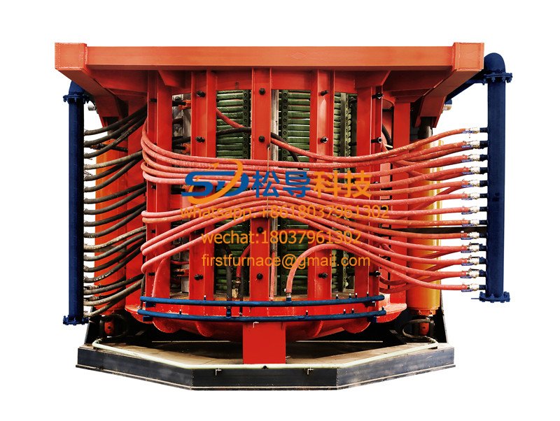
5T Induction Melting Furnace
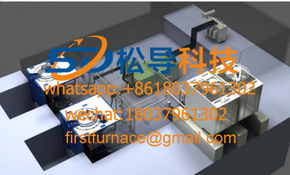
1T One Belt Two Intermediate Frequency F

5T One Belt Two Intermediate Frequency F
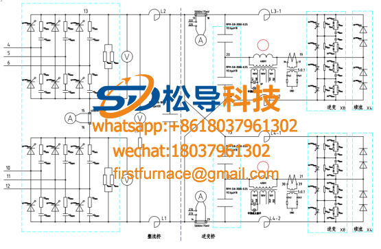
3T One Belt Two Intermediate Frequency F
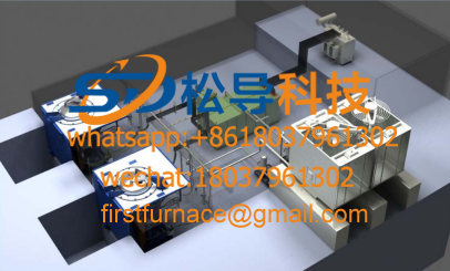
2T One Belt Two Intermediate Frequency F
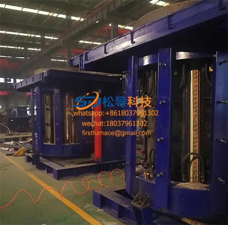
5T Parallel Intermediate Frequency Furna
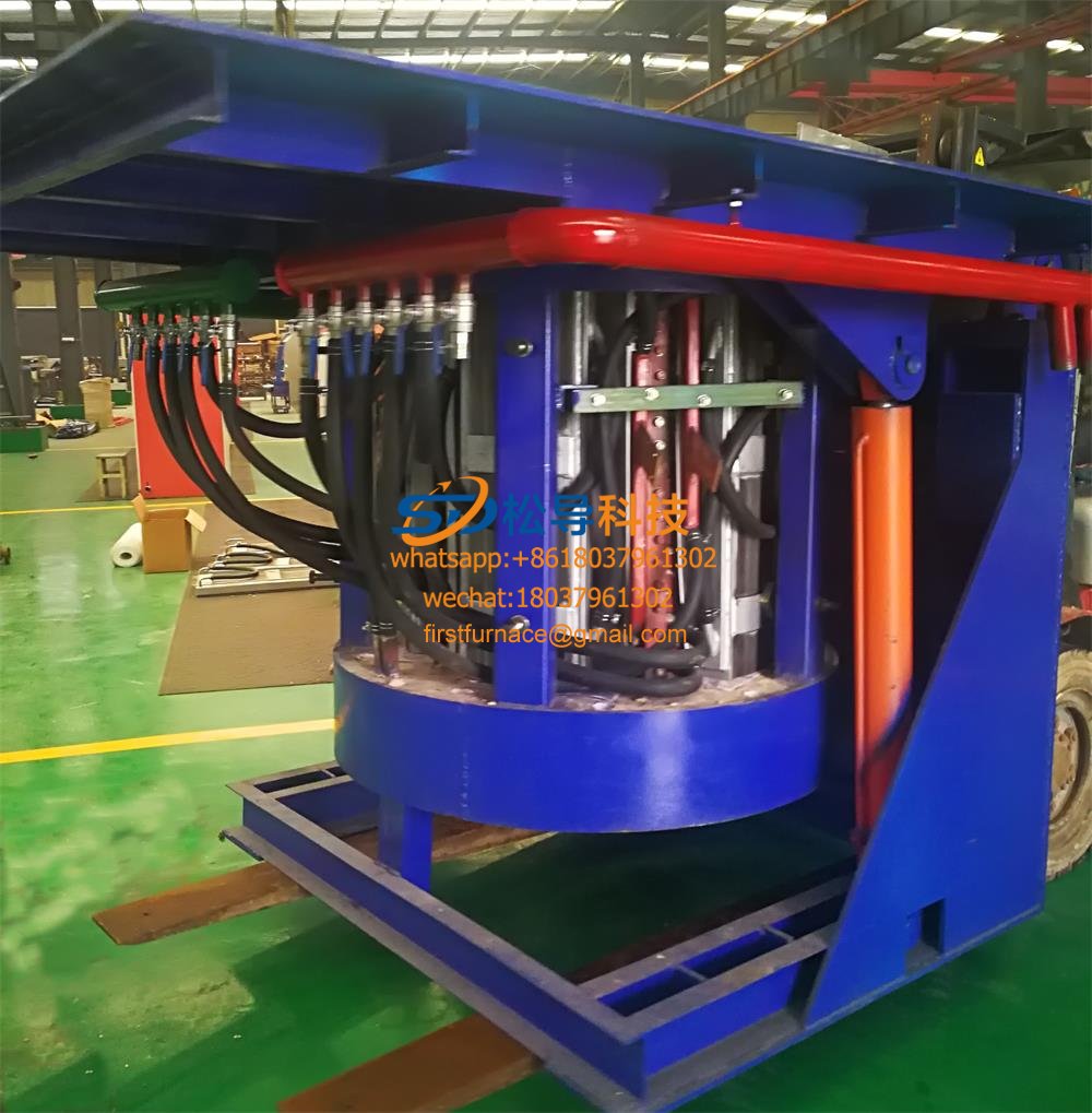
5T Intermediate Frequency Furnace

5T Series Intermediate Frequency Furnace
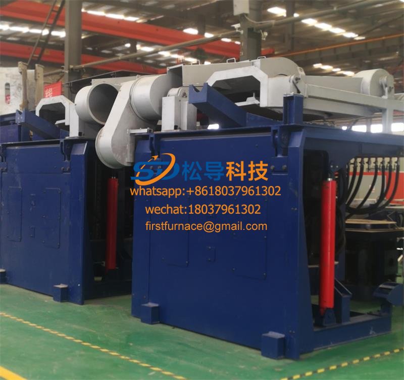
3T Series Intermediate Frequency Furnace
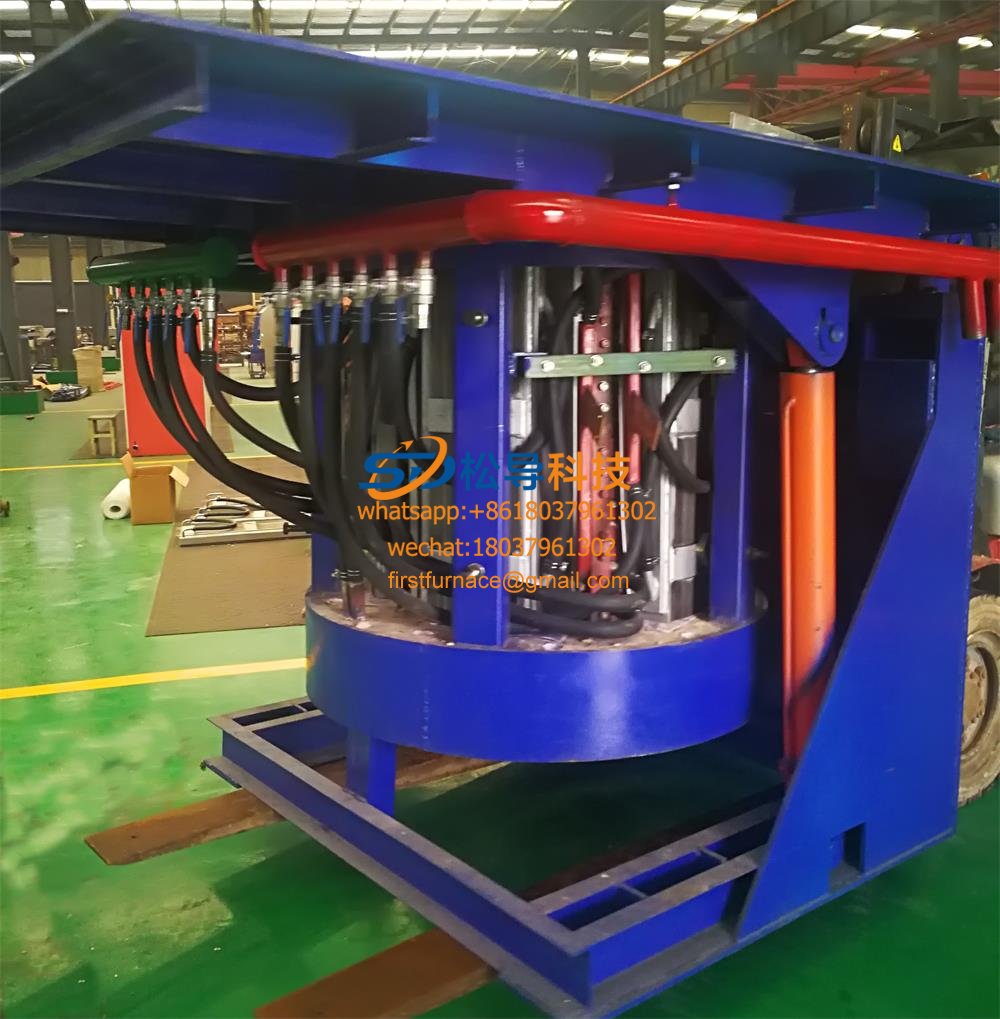
2T Series Intermediate Frequency Furnace
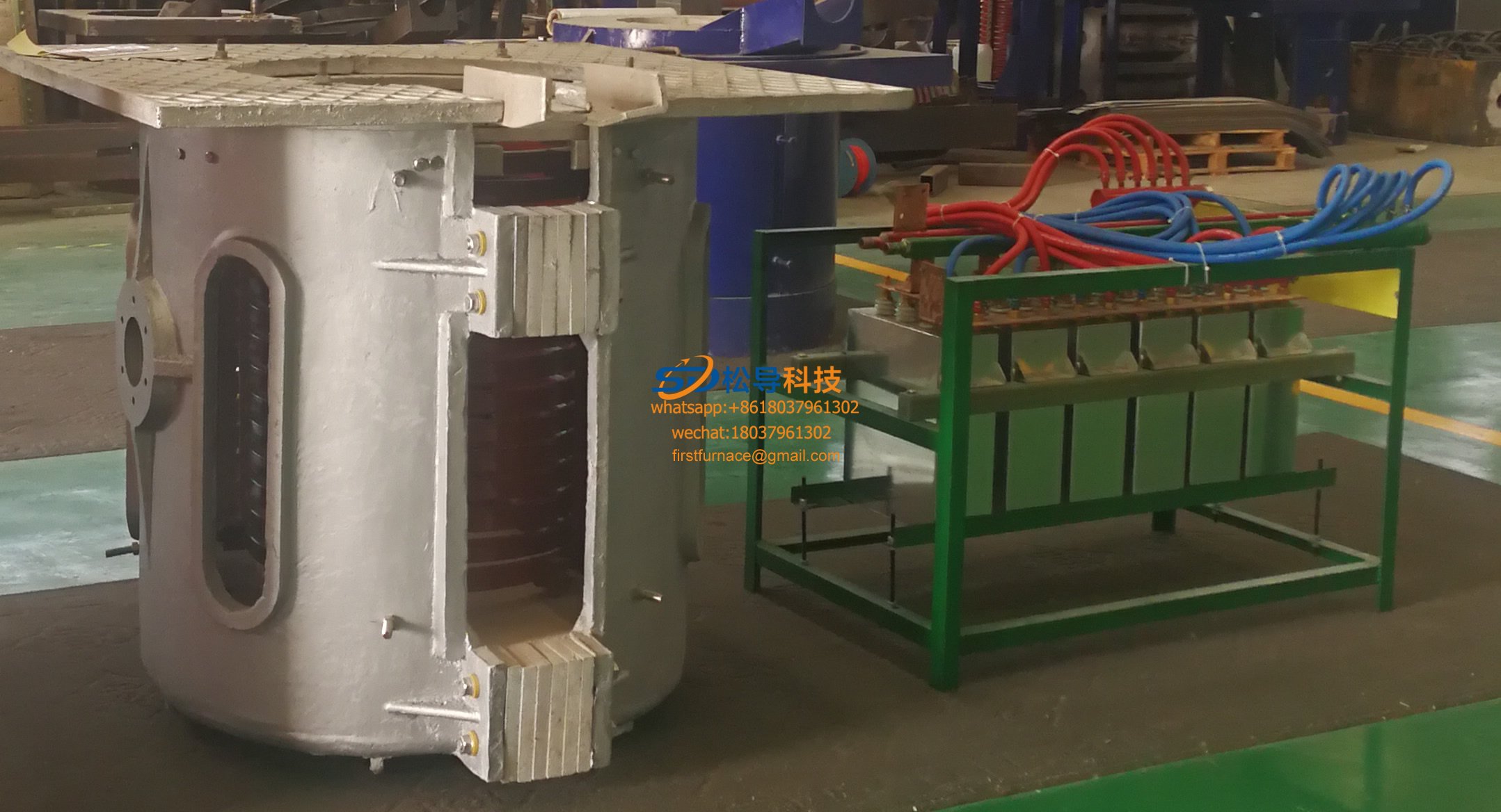
1T Series Intermediate Frequency Furnace
0.5T Series Intermediate Frequency Furna

0.25T Series Intermediate Frequency Furn
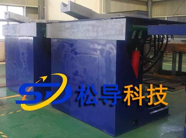
1T Parallel Intermediate Frequency Furna
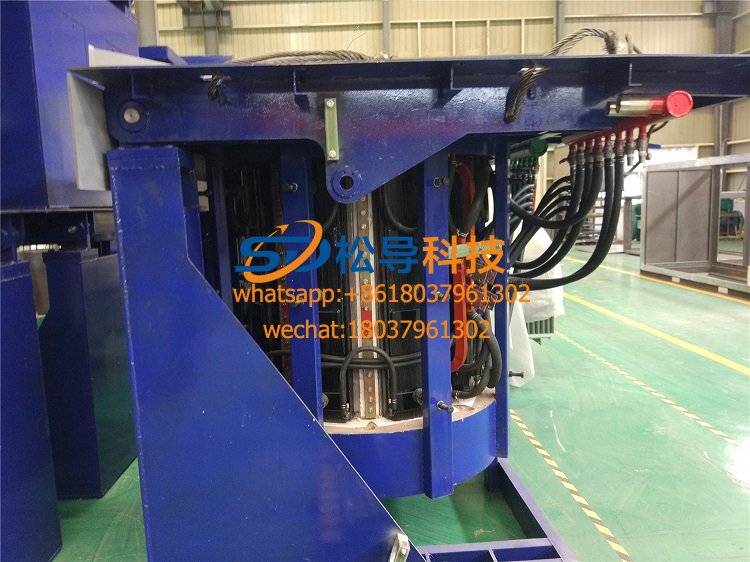
2T Parallel Intermediate Frequency Furna
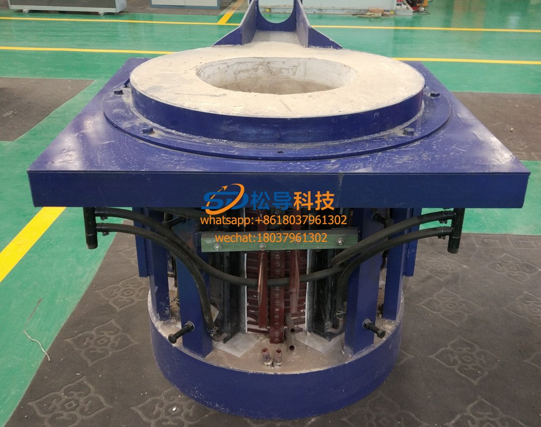
0.5T Parallel Intermediate Frequency Fur


