Sales hot line ( 24 hours service): 18037961302
E-Mail: firstfurnace@gmail.com
whatsapp:+8618037961302
Adress: Luoxin Industrial Park, Luoyang, HenanLarge diameter steel pipe quen
Piston rod quenching and tempe
Grinding rod quenching and tem
High frequency induction heate
Quenching equipment for machin
Round steel end heating furnac
Steel pipe heat treatment prod
Square steel quenching and tem
Sucker rod quenching and tempe
Thickened petroleum steel pipe
Round steel quenching and temp
Steel pipe quenching and tempe
Steel plate quenching and temp
Induction Hardening Machine&nb
Flywheel ring gear high freque
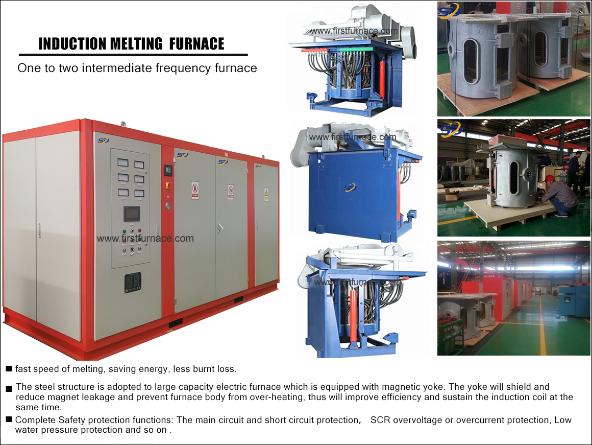
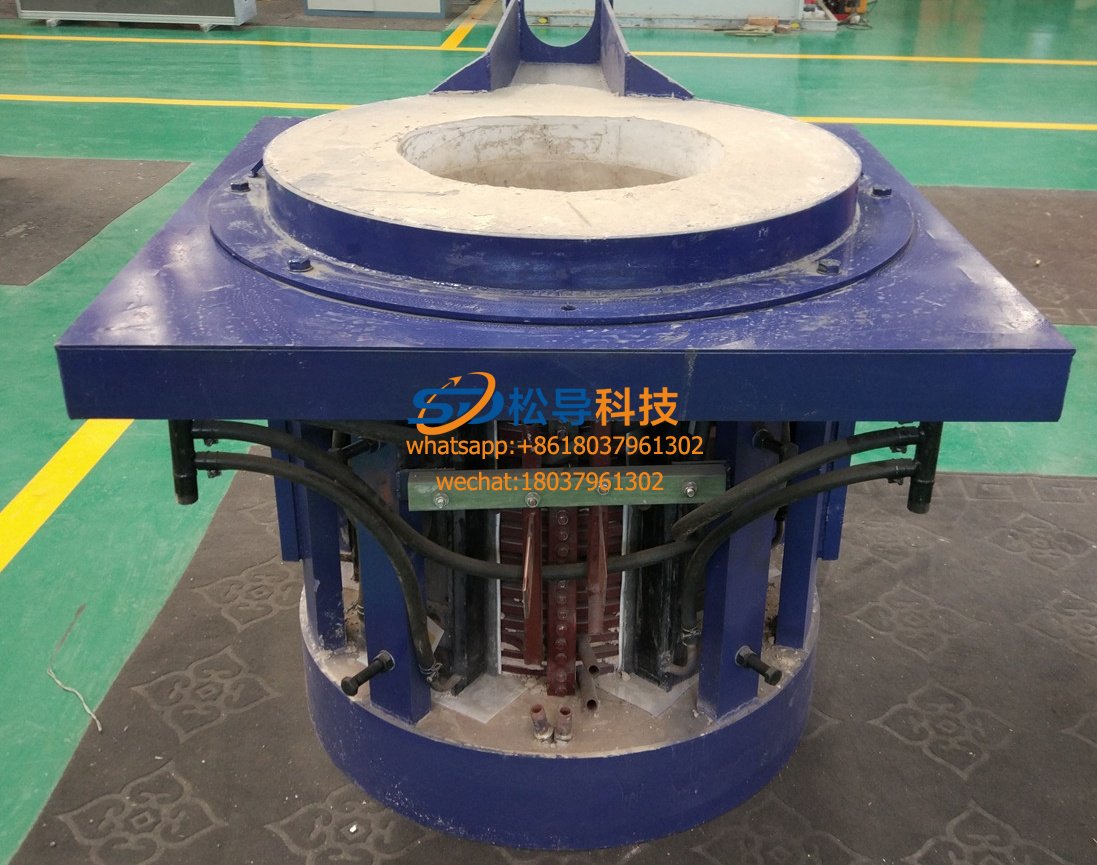
Saving three tons steel melting furnace proper use
(A) connecting three tons steel melting furnace main terminal and a secondary line
1 , the main wiring:
The power supply line is made of copper core cable, and the cross-section of each phase is not less than the listed value.
|
rated power ( KW ) |
Three-phase incoming cross-sectional area ( mm2 ) |
|
100 |
100 |
The power supply and load are connected by ( 4 mm2 ) 25 sets of two-color stranded wires, and the contact at the joint should ensure good and reliable.
2. Note: The main cabinet and the capacitor load cabinet must be reliably connected to the ground.
(B) prior to start checking the steel melting furnace 3 t:
Check that all components are in good condition;
Check that all fasteners are in good condition;
Check if all the wires are disconnected and whether the solder joints are desoldered;
Check if the connection in the installation is correct;
Check the main circuit with a multimeter, and control the insulation of the casing and the insulation between the phases;
Check if the control plugin is placed correctly.
Open the inlet valve and adjust the water pressure to 0.1 ~ 0.2Mpa to check for leaks in each waterway.
(C) 3 t steel melting furnace transmission check:
1. Strictly check the phase sequence. A correspondingly advances the phase B by 120 ° degrees, and C corresponds to the phase B of 120 ° degrees.
2 , control power switch AQ1 , the power indicator of each control board should be on.
3. Check the rectification and inverter trigger pulses with an oscilloscope.
4. Trigger the protection thyristor and the corresponding protection indicator lights.
5. Set the power potentiometer to 0 position, dial out the control board, and check that the relay action should be normal.
D) 3 t steel melting furnace Procedure
1. The operation instructions are shown in Table 3.
|
Serial number |
Name |
symbol |
Use |
|
1 |
AC voltmeter |
M1 |
Indicating AC incoming line voltage |
|
2 |
DC ammeter |
M3 |
Indicates the main circuit DC current |
|
3 |
DC voltmeter |
M2 |
Indicates the main circuit DC voltage |
|
4 |
Output voltmeter |
M4 |
Indicates the output peak voltage |
|
5 |
Control power indicator |
LM1 |
Lights up to indicate that the control loop is powered |
|
6 |
Main power indicator |
LM2 |
Lights up to indicate that the main circuit is powered |
|
7 |
Inverter work indicator |
LM3 |
Lights up to indicate that the power supply is working |
|
8 |
Over current indicator |
LM4 |
Lights up to indicate that the power supply has an overload or short circuit fault. |
|
9 |
Overvoltage indicator |
LM5 |
Lights up to indicate that the power supply has an overvoltage fault. |
|
10 |
Low water pressure indicator |
LM7 |
The water pressure is low until the setting value is on, the power supply cannot be started or automatically stopped. |
|
11 |
Control button |
AQ1 |
Control system power supply after pressing |
|
12 |
Control sub button |
AT1 |
Control system is powered off after pressing |
|
13 |
Main power button |
AQ2 |
After pressing, the main circuit rectifier bridge and the power supply are closed. |
|
14 |
Main power sub button |
AT2 |
After pressing, the main circuit rectifier bridge and power supply are disconnected. |
|
15 |
Inverter work button |
AQ3 |
Power is ready to start after pressing |
|
16 |
Inverter stop button |
AT3 |
After the inverter is pressed, the inverter bridge stops working and the protection system is reset. |
|
17 |
Power adjustment potentiometer |
W2 |
Adjust to zero position before starting. Turn the knob clockwise after starting, the power output power increases |
|
18 |
Temperature alarm indicator |
LM6 |
If the water temperature exceeds the setting value, the power will not start or stop automatically. |
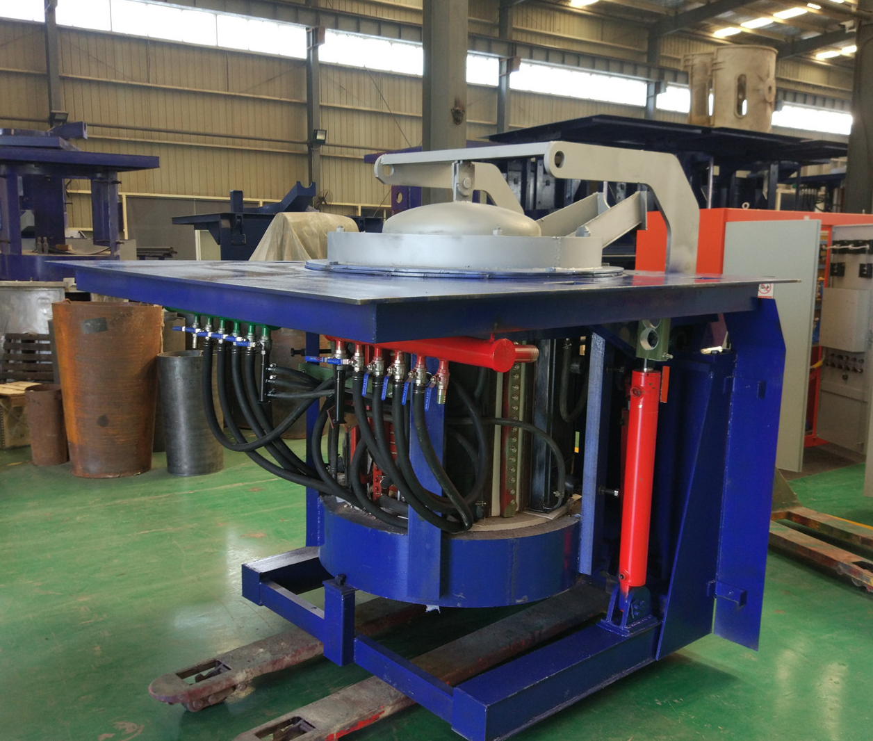
Iron induction furnace
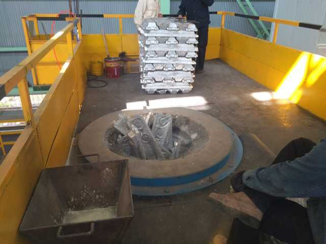
Aluminum melting furnace
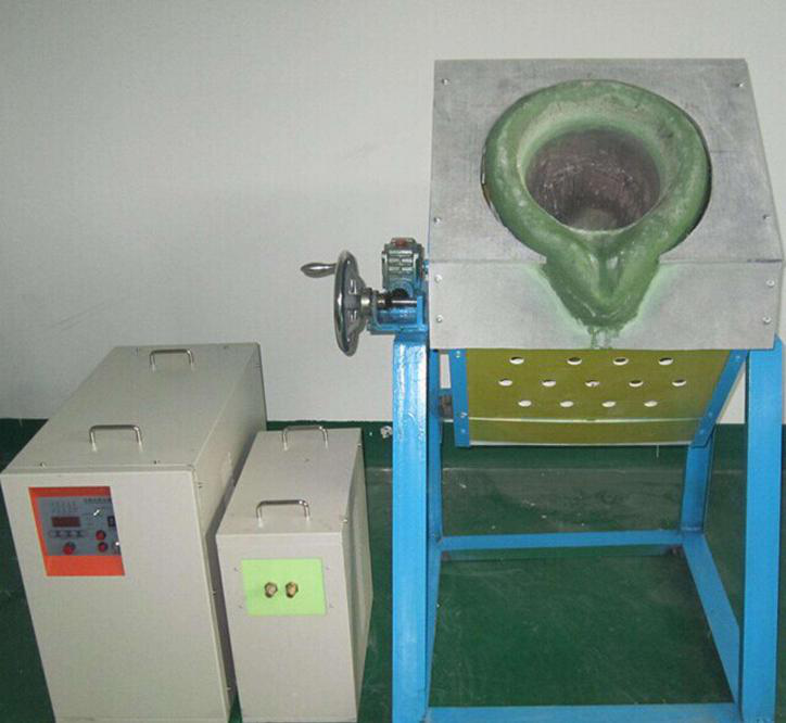
Copper melting furnace
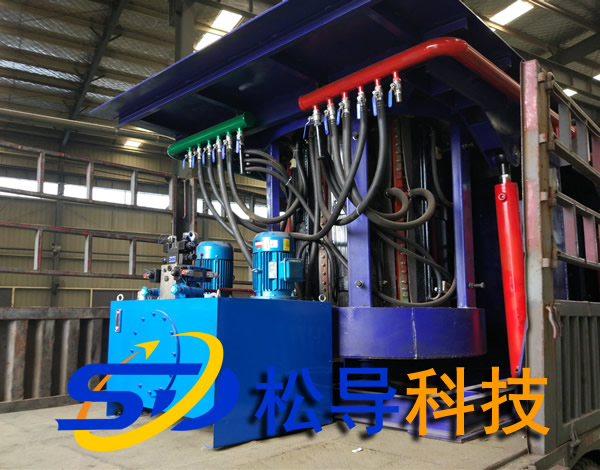
Small steel melting furnace
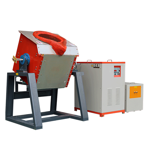
Small induction melting furnace
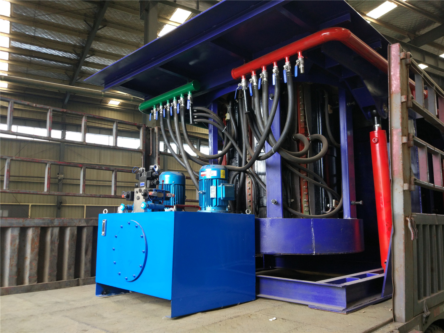
Induction iron furnace
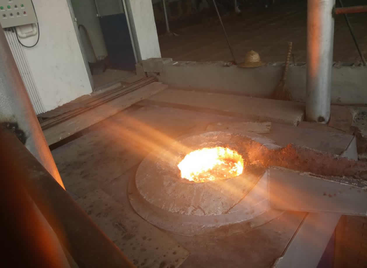
3T intermediate frequency iron melting f
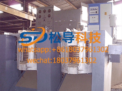
0.25T Intermediate Frequency Furnace
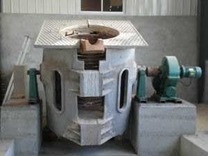
0.5T Intermediate Frequency Furnace
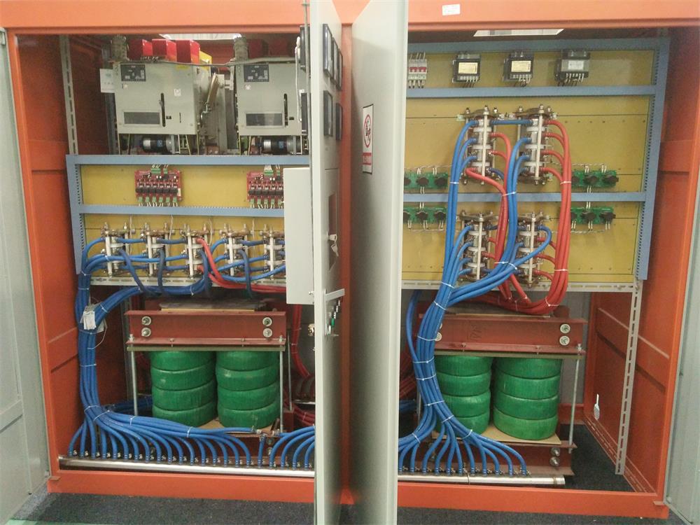
Medium Frequency Furnace

2T Induction Melting Furnace
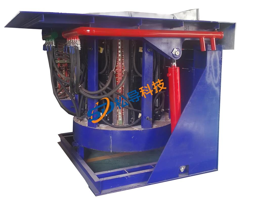
1T Induction Melting Furnace
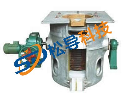
500kg Induction Melting Furnace
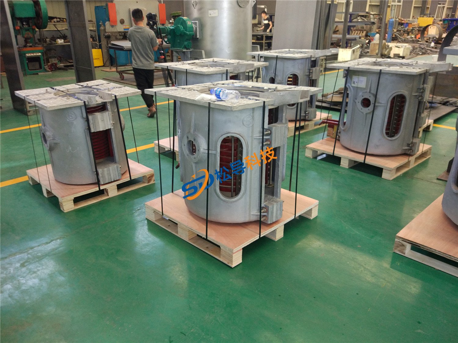
250kg Induction Melting Furnace
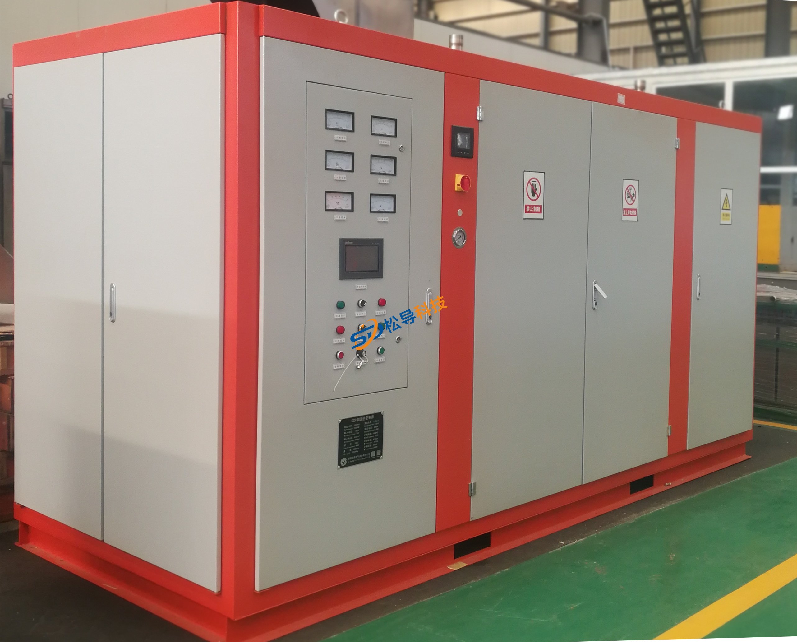
Induction Melting Furnace
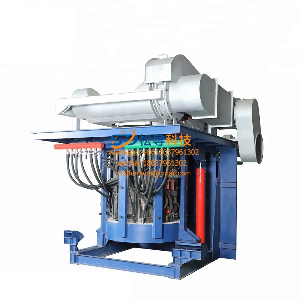
3 T Induction Melting Furnace
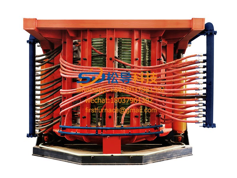
5T Induction Melting Furnace
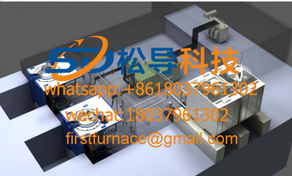
1T One Belt Two Intermediate Frequency F

5T One Belt Two Intermediate Frequency F
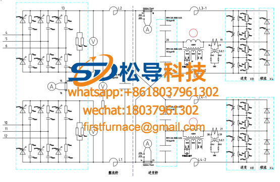
3T One Belt Two Intermediate Frequency F
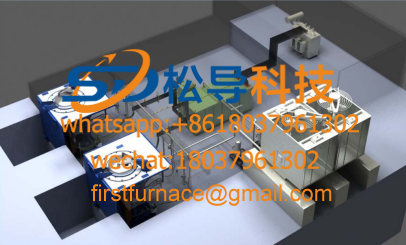
2T One Belt Two Intermediate Frequency F
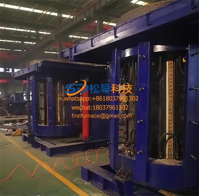
5T Parallel Intermediate Frequency Furna
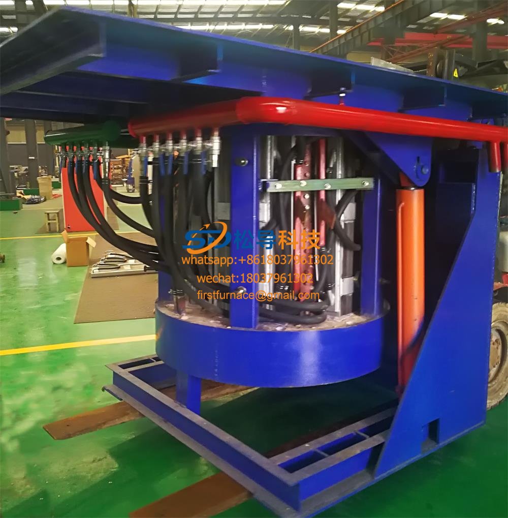
5T Intermediate Frequency Furnace

5T Series Intermediate Frequency Furnace
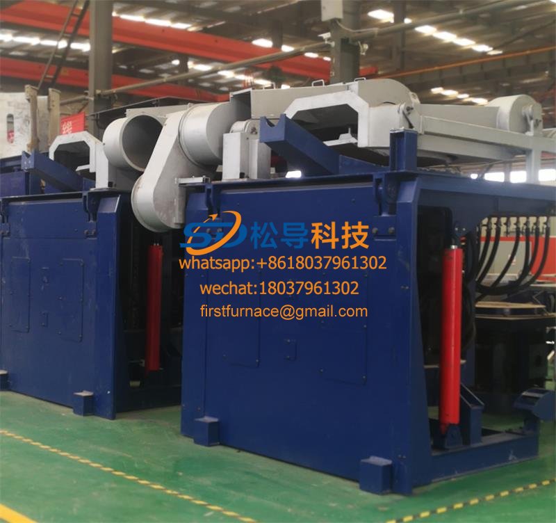
3T Series Intermediate Frequency Furnace
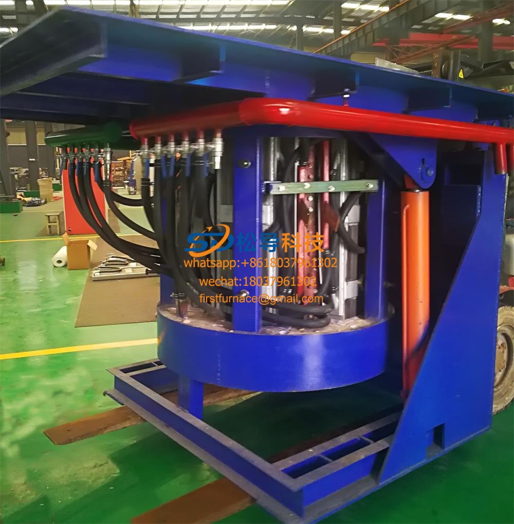
2T Series Intermediate Frequency Furnace
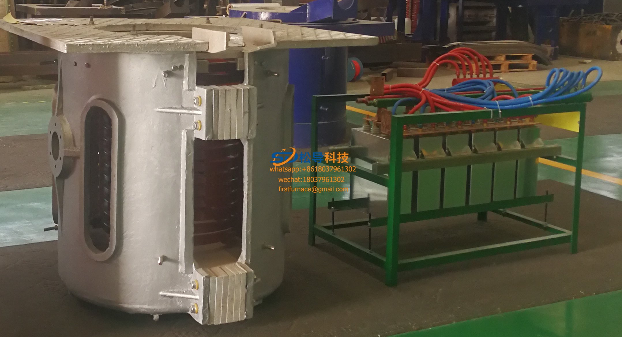
1T Series Intermediate Frequency Furnace
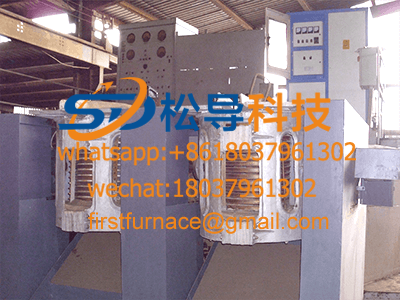
0.5T Series Intermediate Frequency Furna

0.25T Series Intermediate Frequency Furn
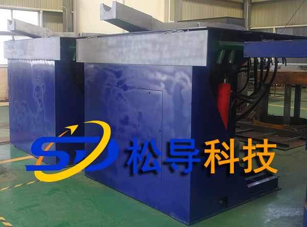
1T Parallel Intermediate Frequency Furna
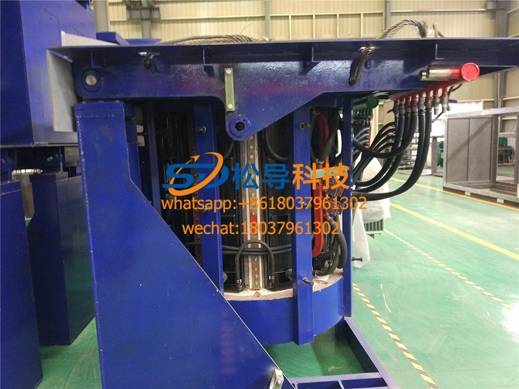
2T Parallel Intermediate Frequency Furna
0.5T Parallel Intermediate Frequency Fur


