Sales hot line ( 24 hours service): 18037961302
E-Mail: firstfurnace@gmail.com
whatsapp:+8618037961302
Adress: Luoxin Industrial Park, Luoyang, HenanLarge diameter steel pipe quen
Piston rod quenching and tempe
Grinding rod quenching and tem
High frequency induction heate
Quenching equipment for machin
Round steel end heating furnac
Steel pipe heat treatment prod
Square steel quenching and tem
Sucker rod quenching and tempe
Thickened petroleum steel pipe
Round steel quenching and temp
Steel pipe quenching and tempe
Steel plate quenching and temp
Induction Hardening Machine&nb
Flywheel ring gear high freque
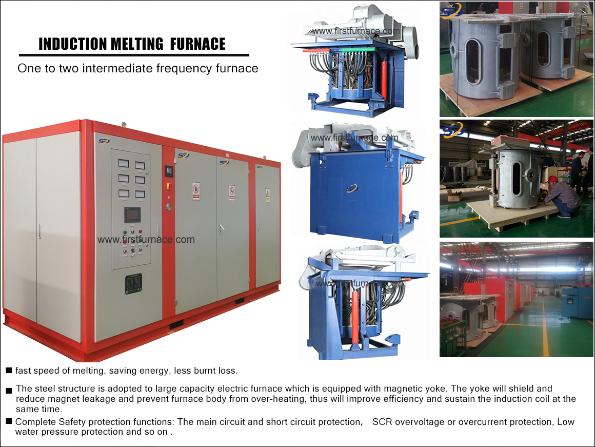
Basic structure of thyristor intermediate frequency induction melting furnace

As shown, the thyristor IF device consists of a controllable or uncontrolled rectifier, a filter, an inverter, and some control and protection circuits. During operation, the three-phase power frequency current is pulsating DC through the rectifier, and is sent to the inverter through the filter into a smooth DC. The inverter uses the thyristor as an electronic switch, which converts the direct current into a higher frequency. Current is supplied to the load. In an intermediate frequency induction furnace, the intermediate frequency current is delivered to the load through the induction coil, and the induction coil is often a component in the inverter. The induction coil and the charge together show a low power factor, and in order to increase the power factor, it is necessary to provide a non-functional amount from the tuning capacitor to the induction heating load. In practice, the capacitor and the induction coil are used in series or in parallel, in series and parallel, whereby the inverter can be divided into three types:
1) When the capacitor and the induction coil form a series resonance in the inverter, it is called a series inverter. The voltage of the series inverter is a function of the voltage of the induction coil, and the current of the inverter is the same as the coil current.
2) When the capacitor and the induction coil form a parallel resonance in the inverter, it is called a parallel inverter. The voltage of the parallel inverter is the same as the coil voltage, and the current of the inverter is much smaller than the coil current. The former is a function of the latter. The performance of the parallel inverter is closer to that of the intermediate frequency generator set, and it is widely used in induction furnaces.
3) A series-parallel inverter that combines the characteristics of series and parallel inverters.
In addition, there are multiplier inverters that can increase the operating frequency. These are passive inverters because they do not send the converted AC power back to the power supply.
In fact, passive inverters have a wide variety of wiring structures and many classification methods. For example, according to the number of phases output by the inverter, it can be divided into single phase, three phase and multiphase; according to the line structure, it can be divided into symmetry and asymmetry; or bridge and non-bridge. The circuit structure of the inverter for induction heating mainly includes single-phase bridge parallel, series, series-parallel and frequency-doubled inverter lines. These lines have their own characteristics, it is impossible to clearly define their application range, and they cannot simply compare their advantages and disadvantages.
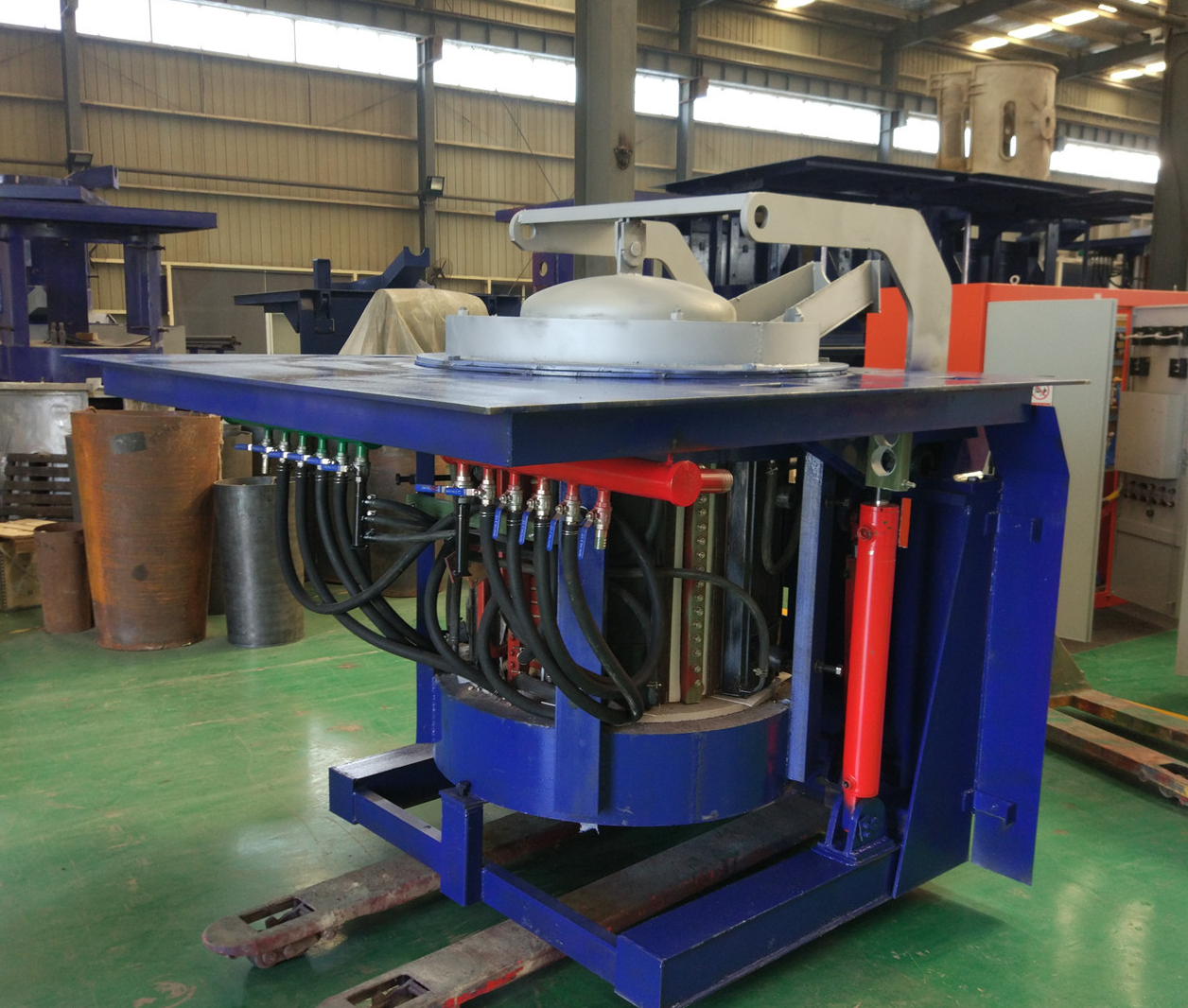
Iron induction furnace
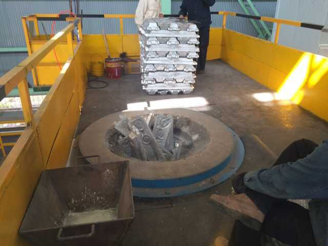
Aluminum melting furnace
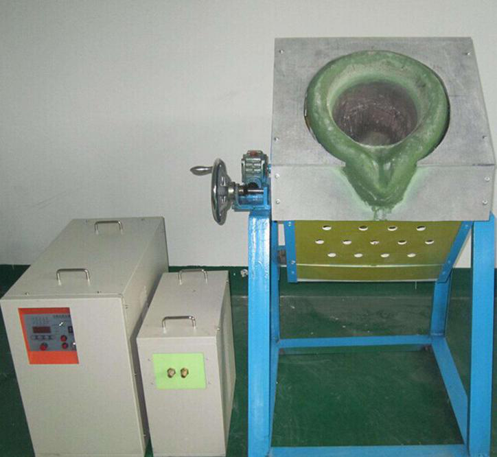
Copper melting furnace
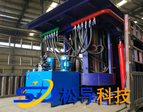
Small steel melting furnace
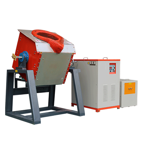
Small induction melting furnace
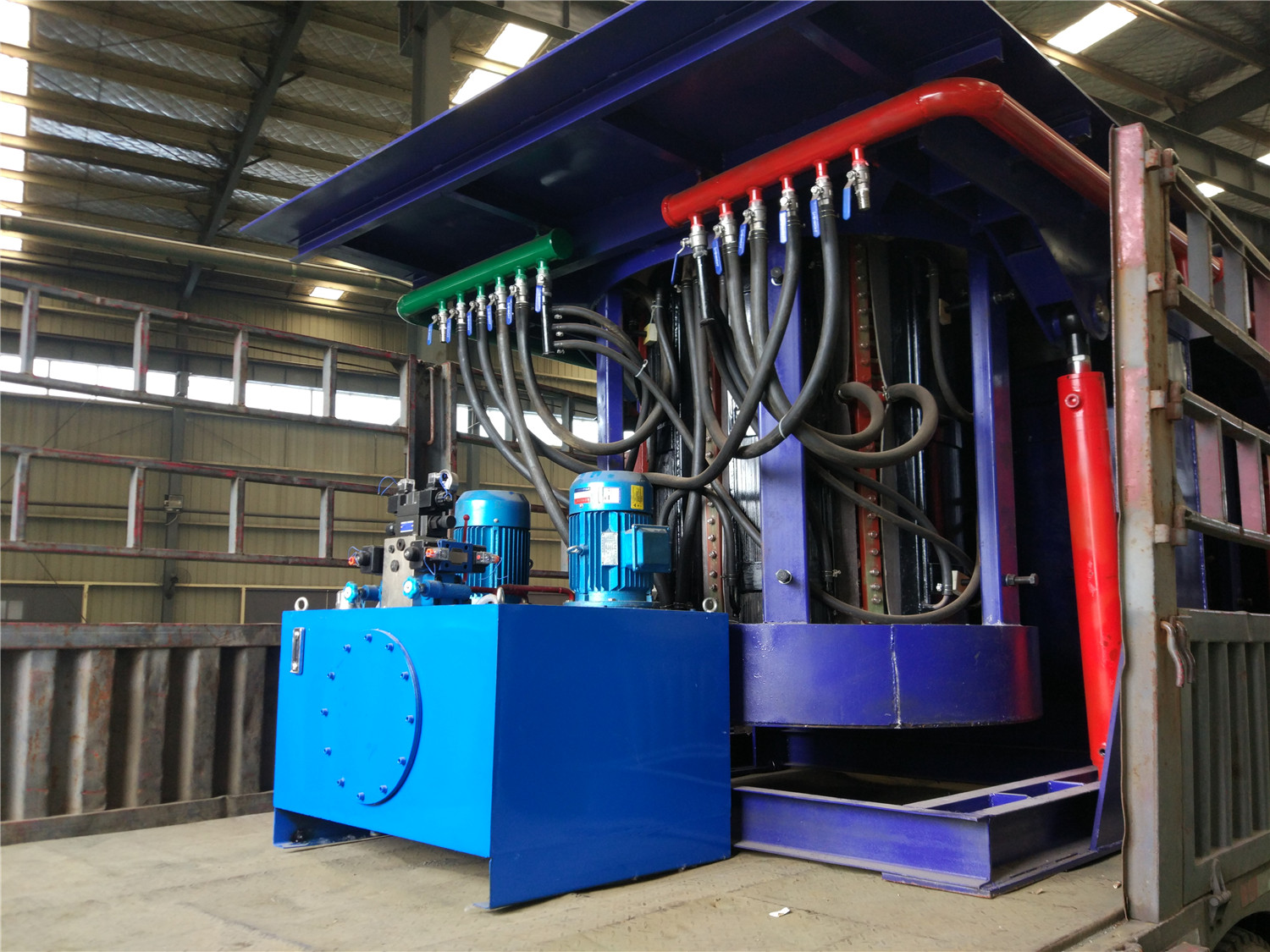
Induction iron furnace
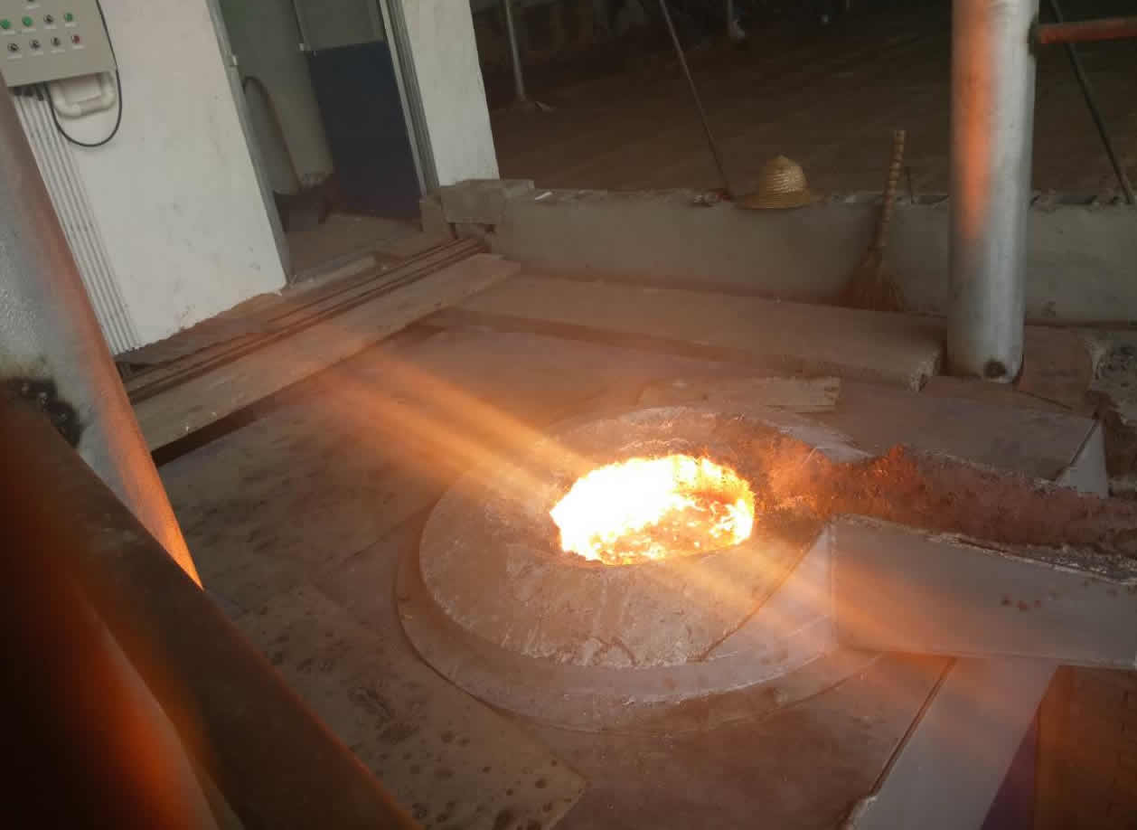
3T intermediate frequency iron melting f
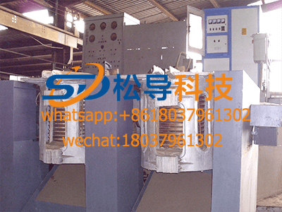
0.25T Intermediate Frequency Furnace
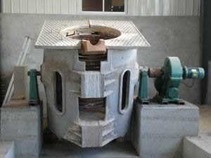
0.5T Intermediate Frequency Furnace
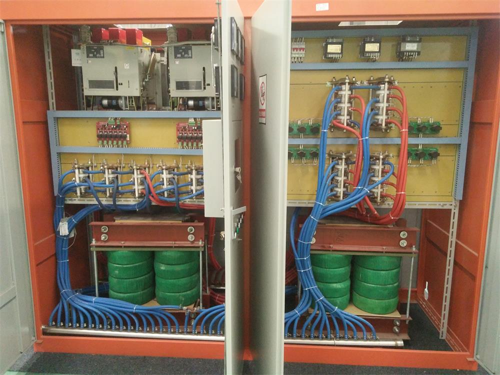
Medium Frequency Furnace

2T Induction Melting Furnace
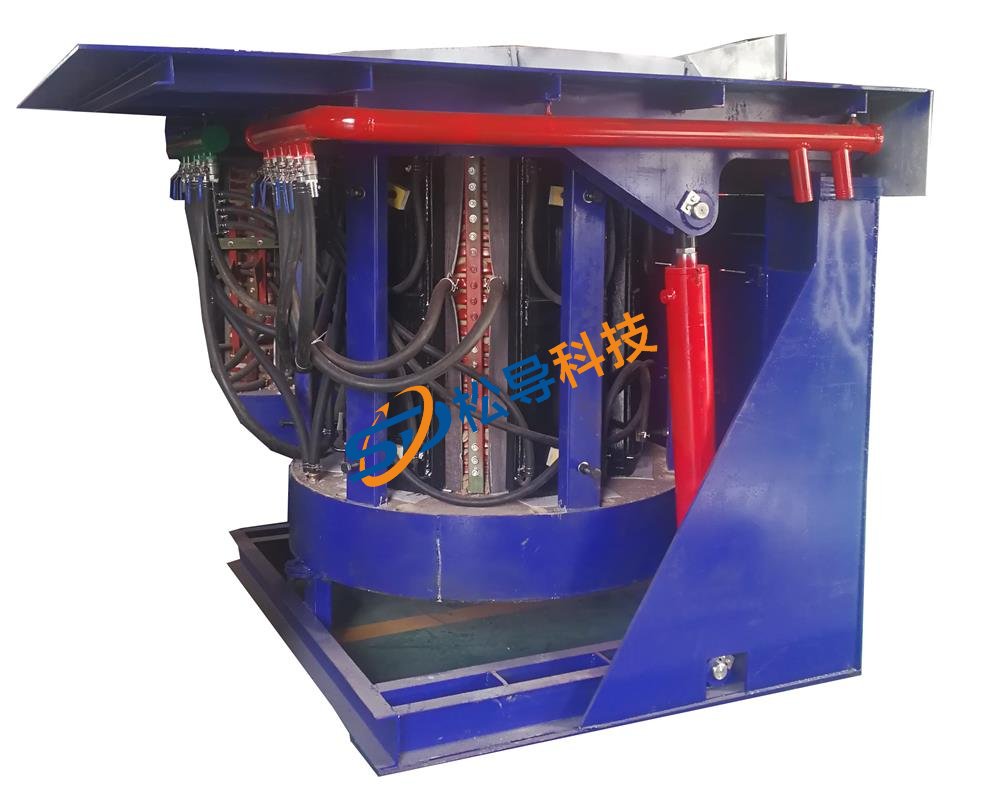
1T Induction Melting Furnace
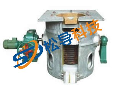
500kg Induction Melting Furnace
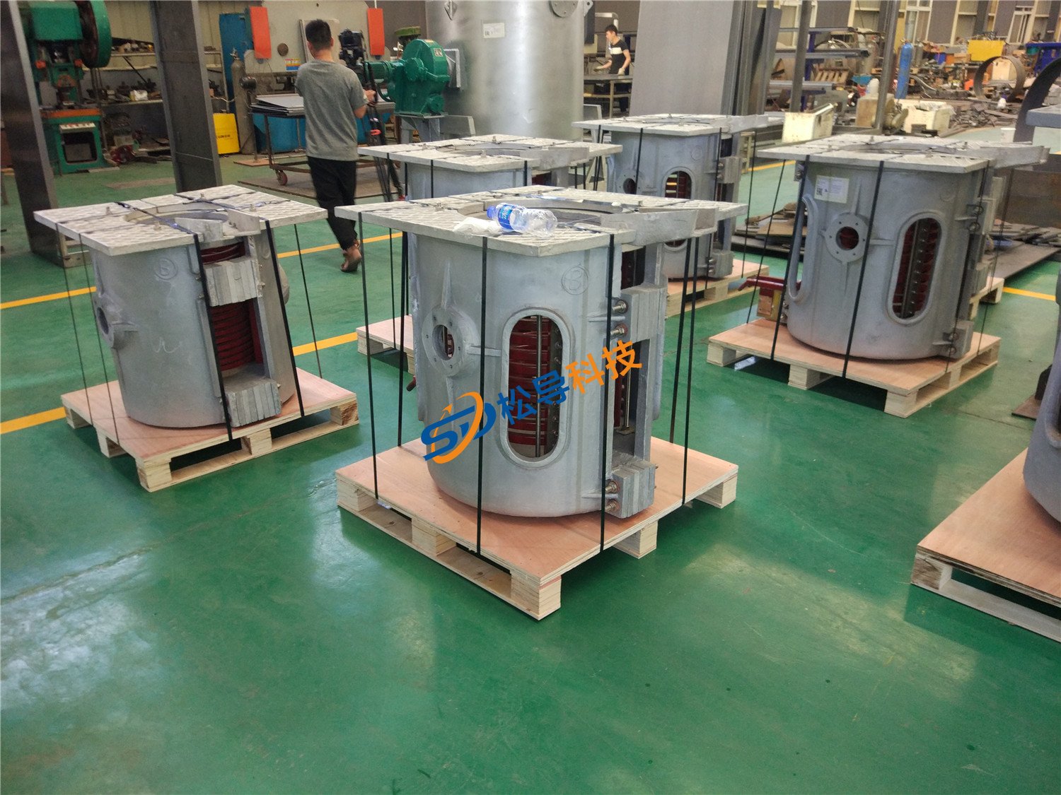
250kg Induction Melting Furnace
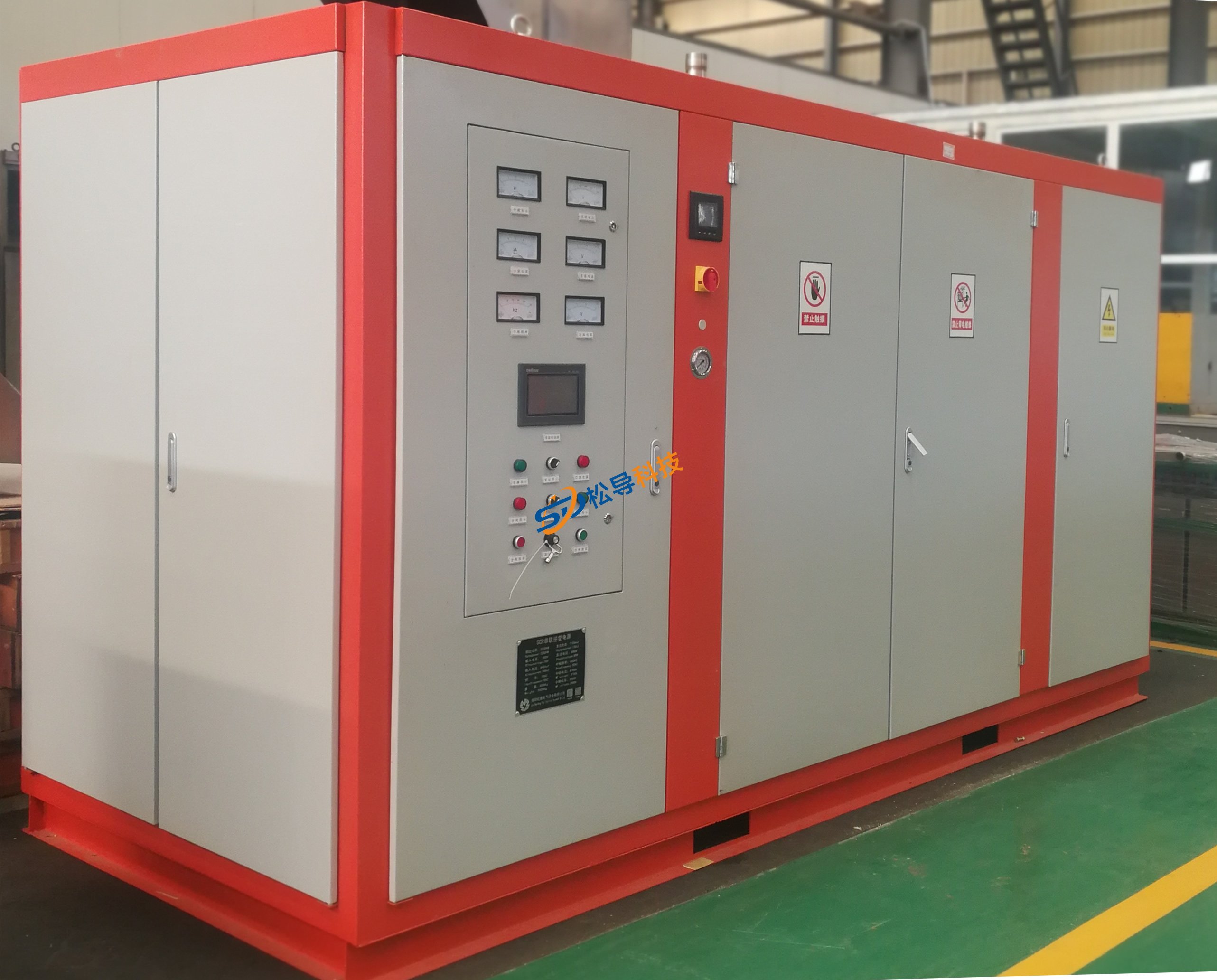
Induction Melting Furnace
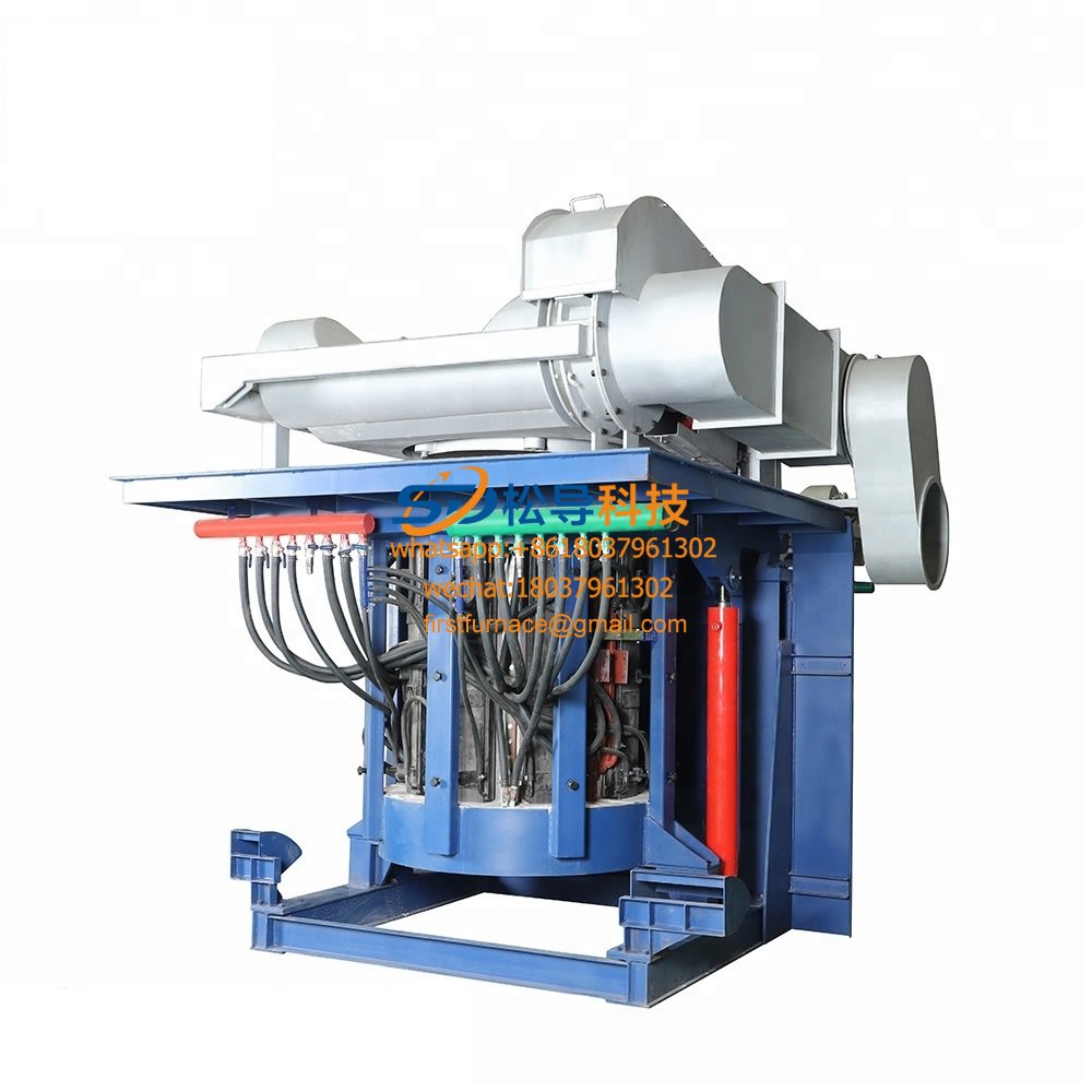
3 T Induction Melting Furnace
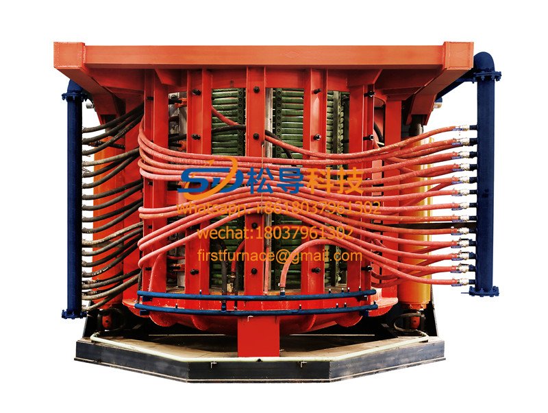
5T Induction Melting Furnace
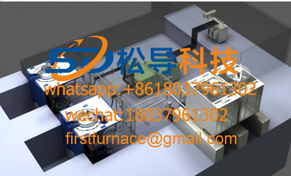
1T One Belt Two Intermediate Frequency F

5T One Belt Two Intermediate Frequency F
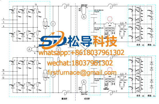
3T One Belt Two Intermediate Frequency F
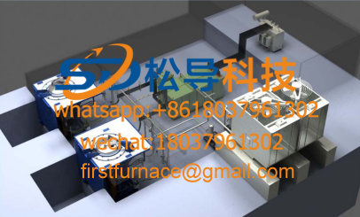
2T One Belt Two Intermediate Frequency F
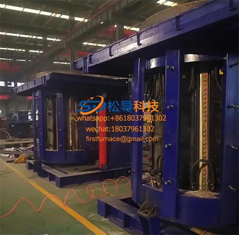
5T Parallel Intermediate Frequency Furna
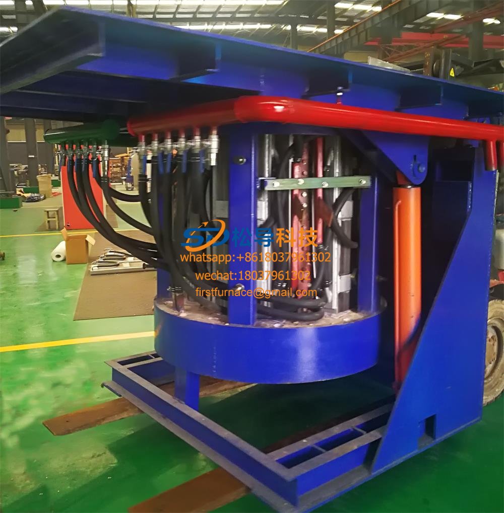
5T Intermediate Frequency Furnace

5T Series Intermediate Frequency Furnace
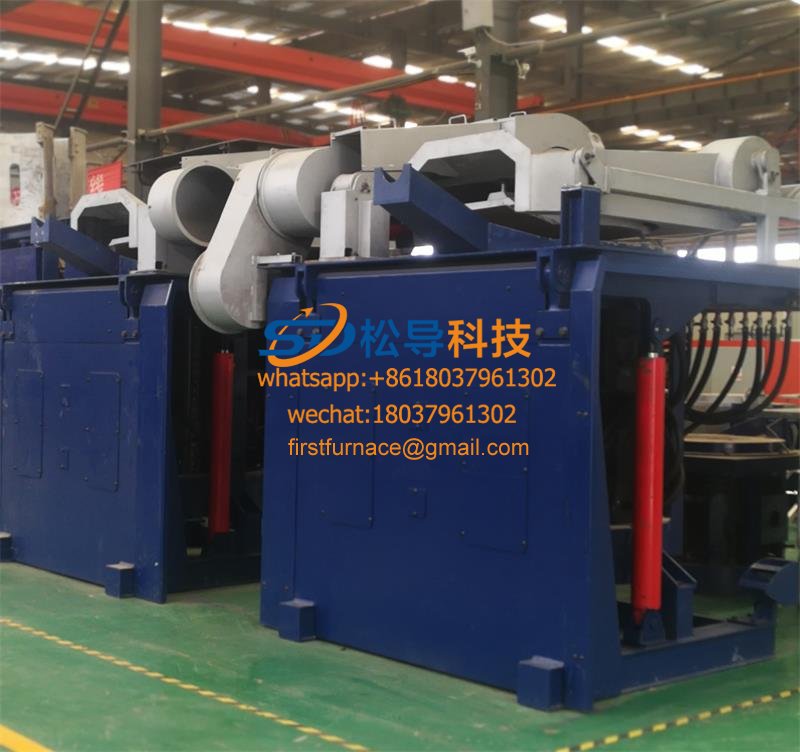
3T Series Intermediate Frequency Furnace
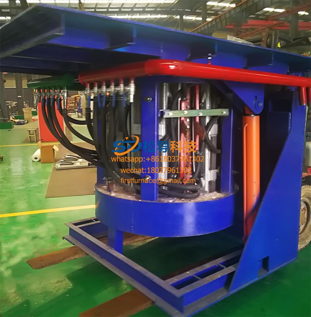
2T Series Intermediate Frequency Furnace
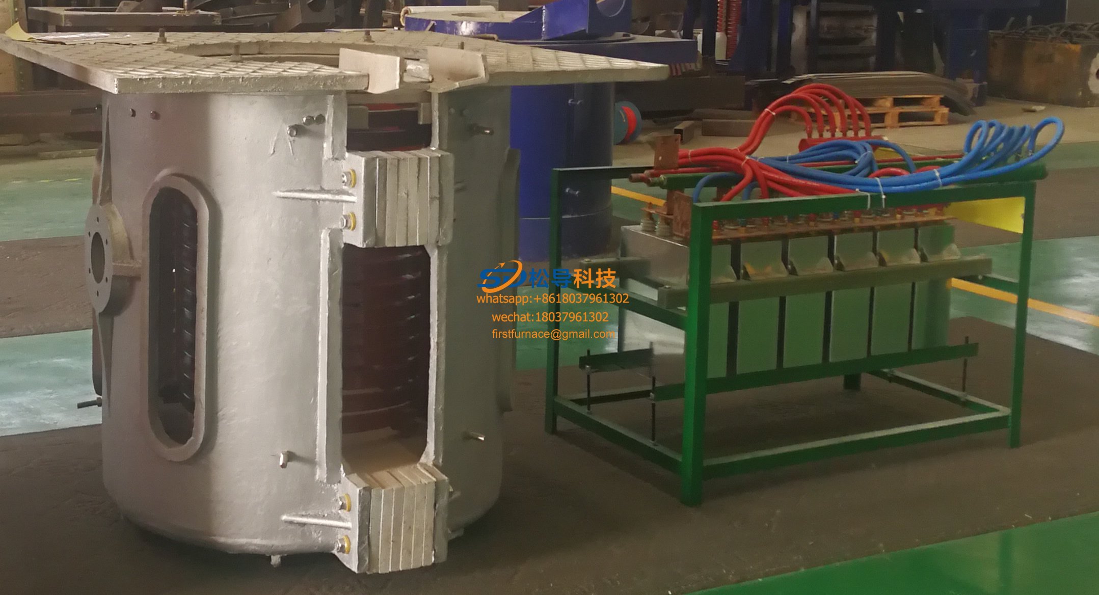
1T Series Intermediate Frequency Furnace
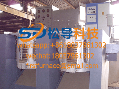
0.5T Series Intermediate Frequency Furna

0.25T Series Intermediate Frequency Furn
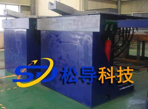
1T Parallel Intermediate Frequency Furna
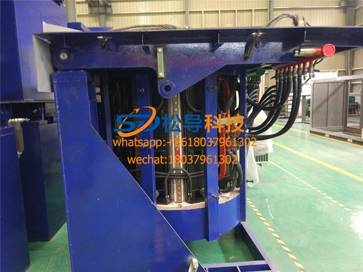
2T Parallel Intermediate Frequency Furna
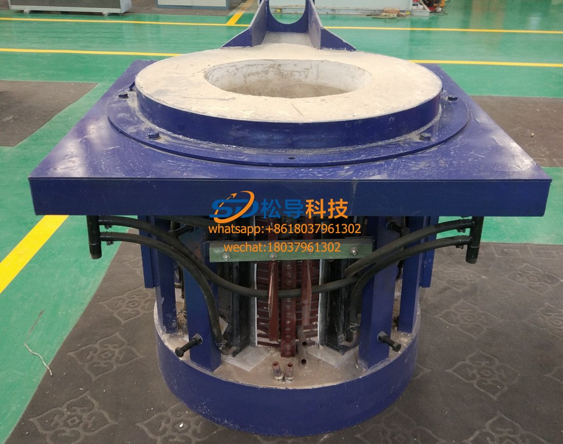
0.5T Parallel Intermediate Frequency Fur


