Sales hot line ( 24 hours service):+86 13015583380
E-Mail: firstfurnace@gmail.com
whatsapp:+86 13015583380
Adress: Luoxin Industrial Park, Luoyang, HenanLarge diameter steel pipe quen
Piston rod quenching and tempe
Grinding rod quenching and tem
High frequency induction heate
Quenching equipment for machin
Round steel end heating furnac
Steel pipe heat treatment prod
Square steel quenching and tem
Sucker rod quenching and tempe
Thickened petroleum steel pipe
Round steel quenching and temp
Steel pipe quenching and tempe
Steel plate quenching and temp
Induction Hardening Machine&nb
Flywheel ring gear high freque
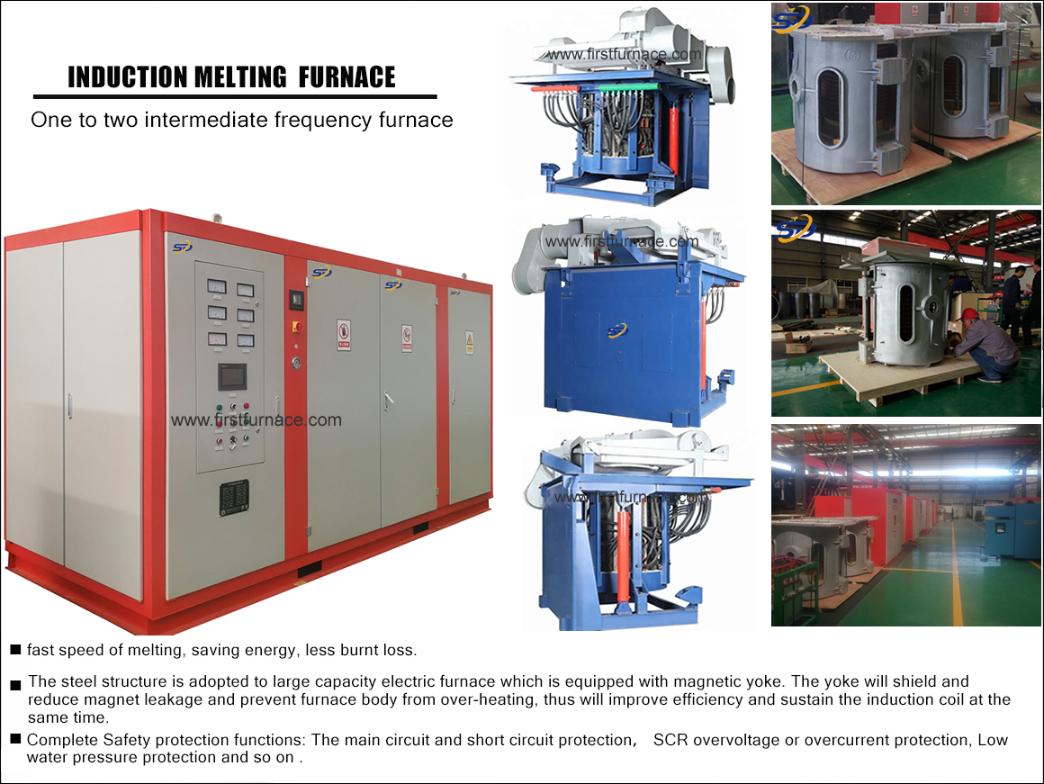
Design of Main Circuit Structure of Series Resonant Medium Frequency Electric Furnace
This design describes the overall structure of the main circuit of the series resonant medium frequency electric furnace system, focusing on the main theoretical analysis of the basic circuit. This design is based on the domestic and international related parallel resonant electric furnace and series resonant electric furnace circuit, combined with the development and use of domestic electric furnace, appropriate reference to the relevant information, the experimental research made, and finally obtained.
The structural design of the main circuit of the series resonant medium frequency electric furnace includes: high voltage 10KV incoming line switch cabinet design, high voltage 10KV system for small current grounding system, design over voltage and over current protection, design voltage, current and energy metering; design rectification The circuit, the filter circuit and the inverter circuit illustrate the principle. Explain the working principle of the component and the circuit design principle and basis, and explain the principle of reducing harmonics and energy saving.
The basic idea of this design is that the first 50 Hz three-phase alternating current is rectified into direct current through the thyristor three-phase full-controlled rectifier bridge rectifier circuit, and then the obtained direct current is converted into an inverter circuit by controlling the conduction frequency of the IGBT. The intermediate frequency AC is finally output to the load. It is necessary to design a protection circuit. The function of the protection circuit is to solve the problem of changes in the load, changes in the voltage, current, and frequency of the system caused by fluctuations in the power grid and changes in the load impedance, and variations in the overlap time of the inverter current.
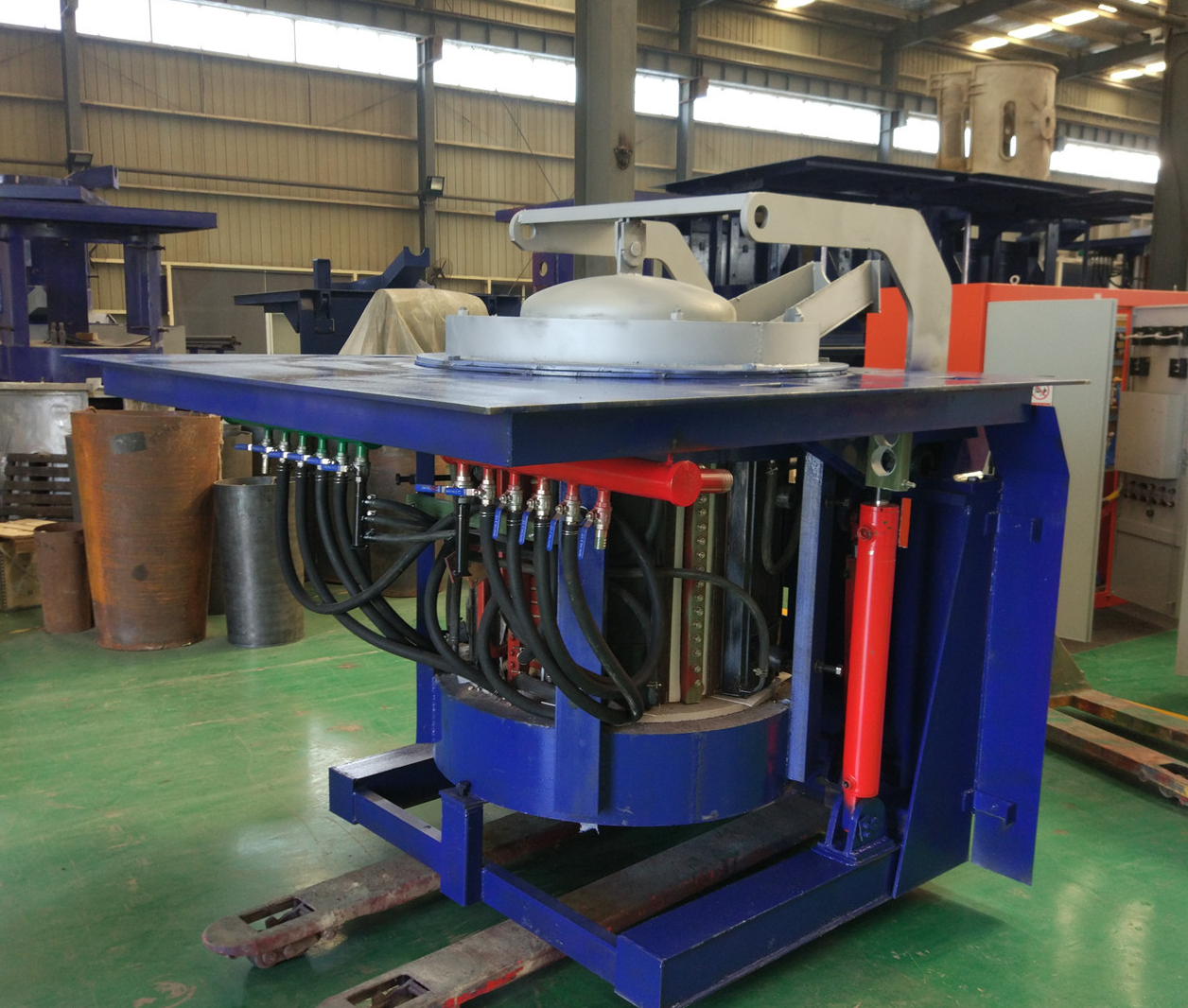
Iron induction furnace
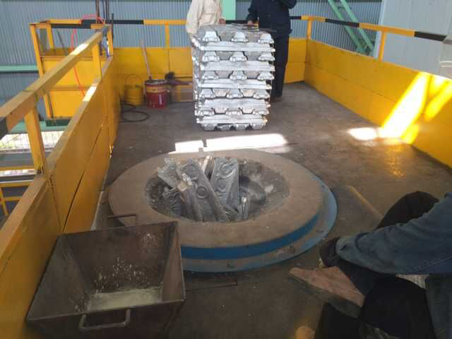
Aluminum melting furnace
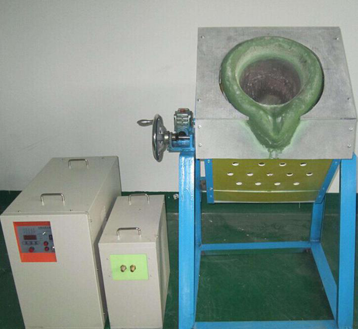
Copper melting furnace
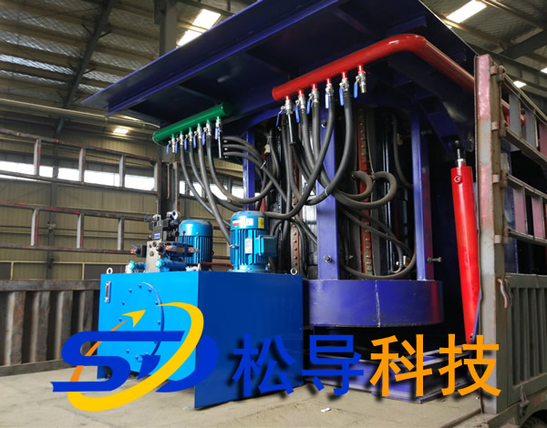
Small steel melting furnace
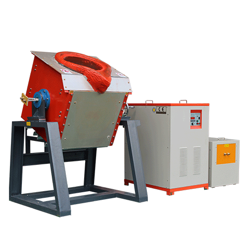
Small induction melting furnace
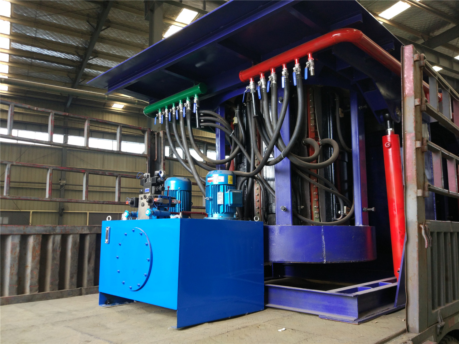
Induction iron furnace
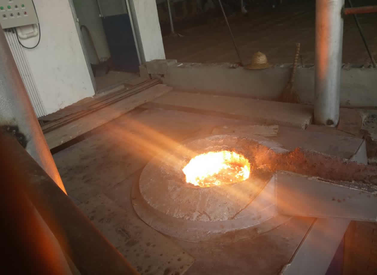
3T intermediate frequency iron melting f
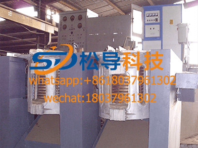
0.25T Intermediate Frequency Furnace
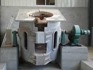
0.5T Intermediate Frequency Furnace
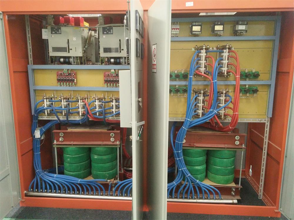
Medium Frequency Furnace

2T Induction Melting Furnace
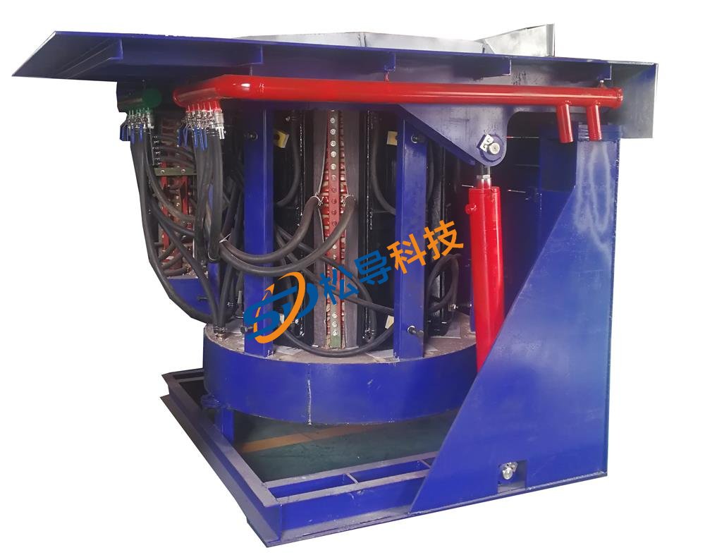
1T Induction Melting Furnace
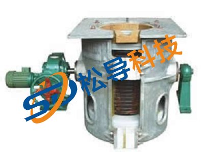
500kg Induction Melting Furnace
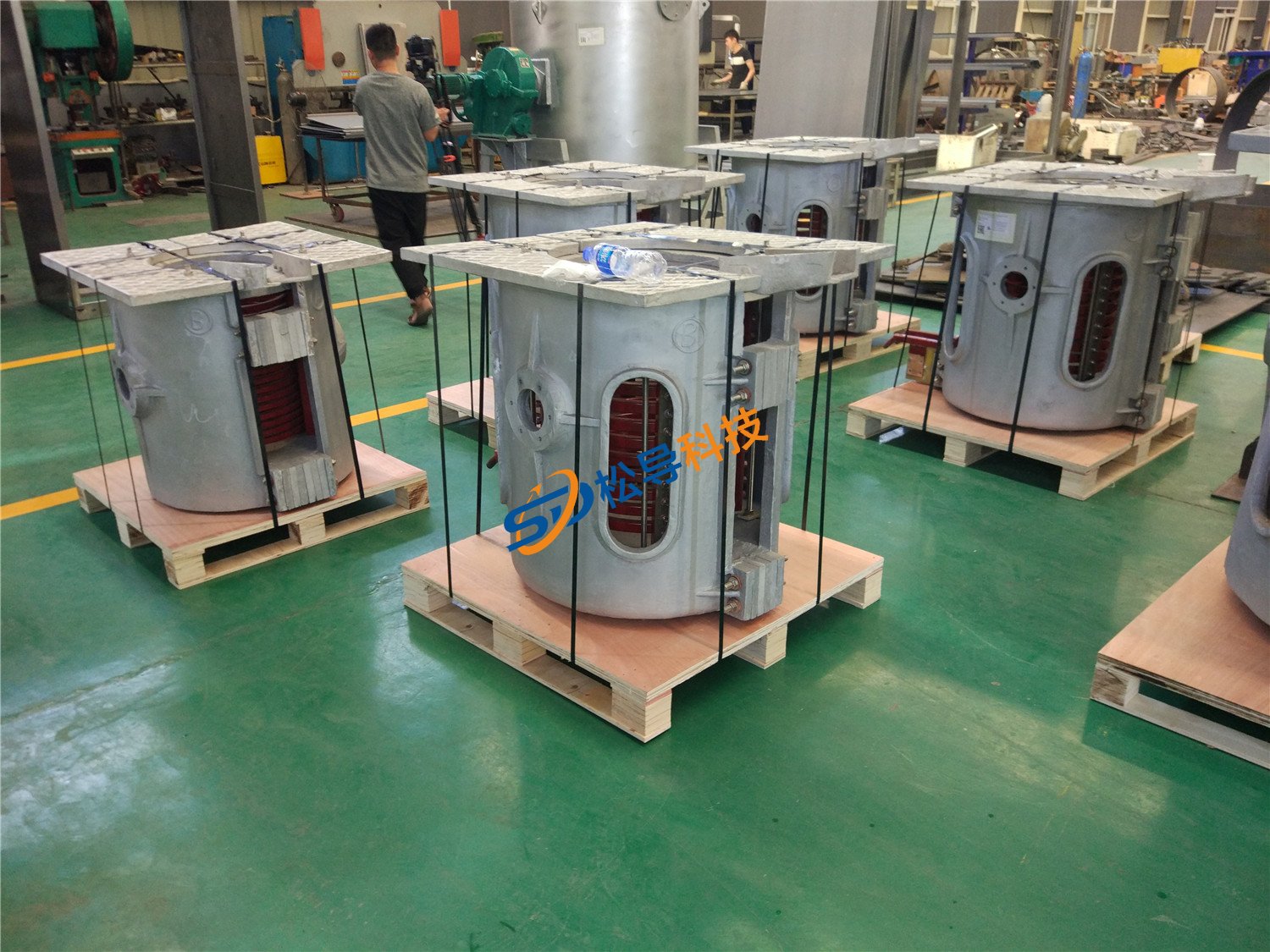
250kg Induction Melting Furnace
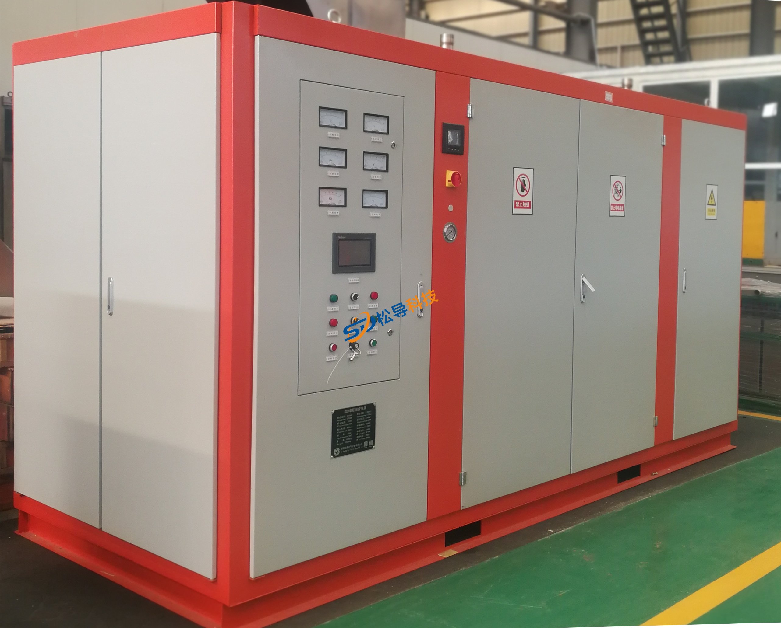
Induction Melting Furnace
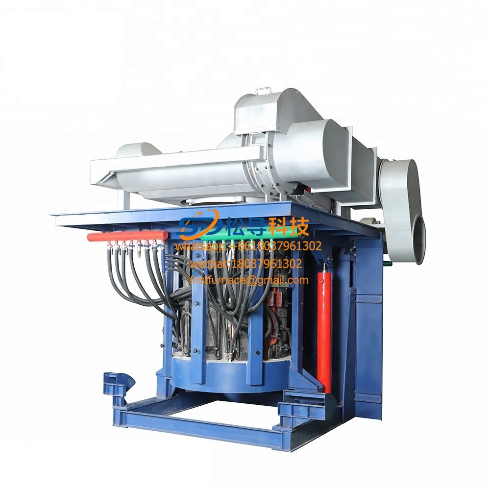
3 T Induction Melting Furnace
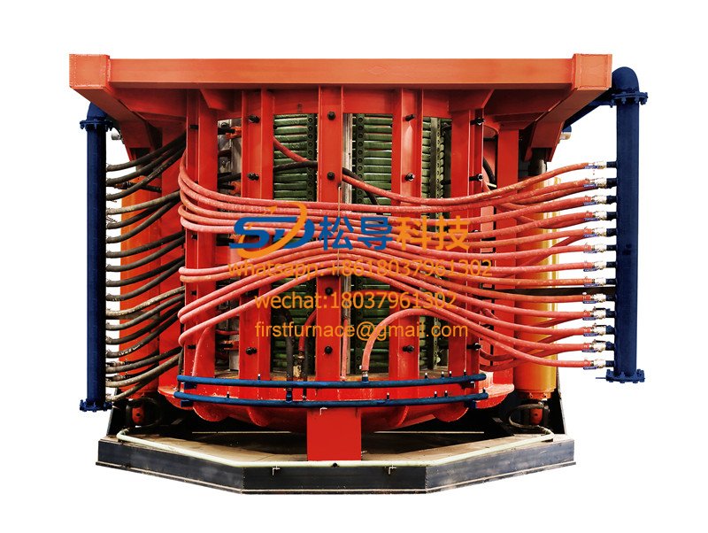
5T Induction Melting Furnace
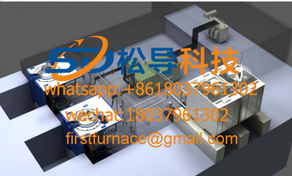
1T One Belt Two Intermediate Frequency F

5T One Belt Two Intermediate Frequency F
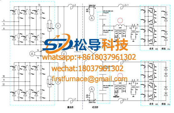
3T One Belt Two Intermediate Frequency F
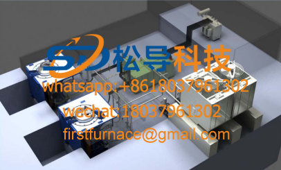
2T One Belt Two Intermediate Frequency F
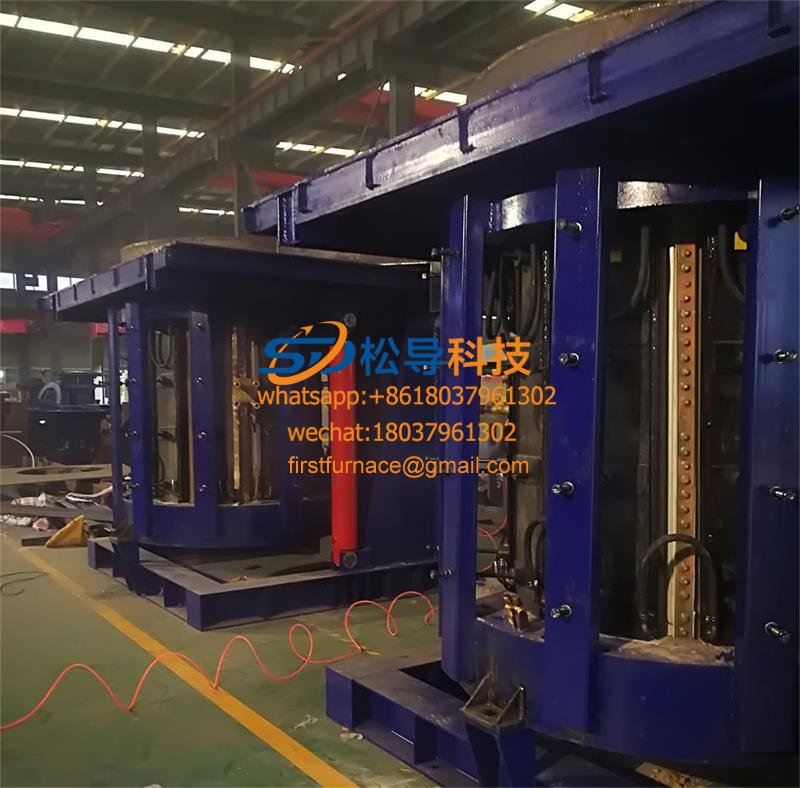
5T Parallel Intermediate Frequency Furna
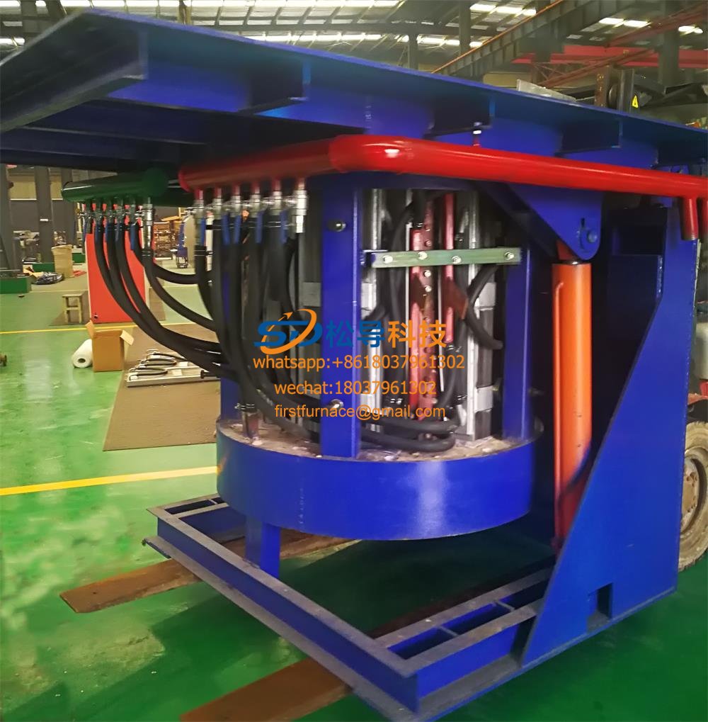
5T Intermediate Frequency Furnace

5T Series Intermediate Frequency Furnace
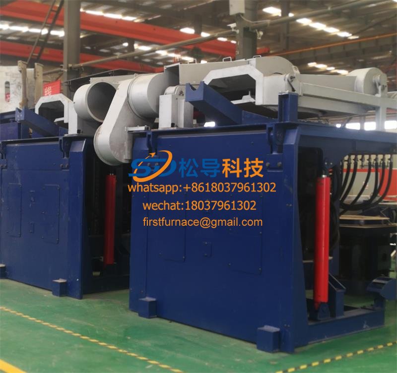
3T Series Intermediate Frequency Furnace
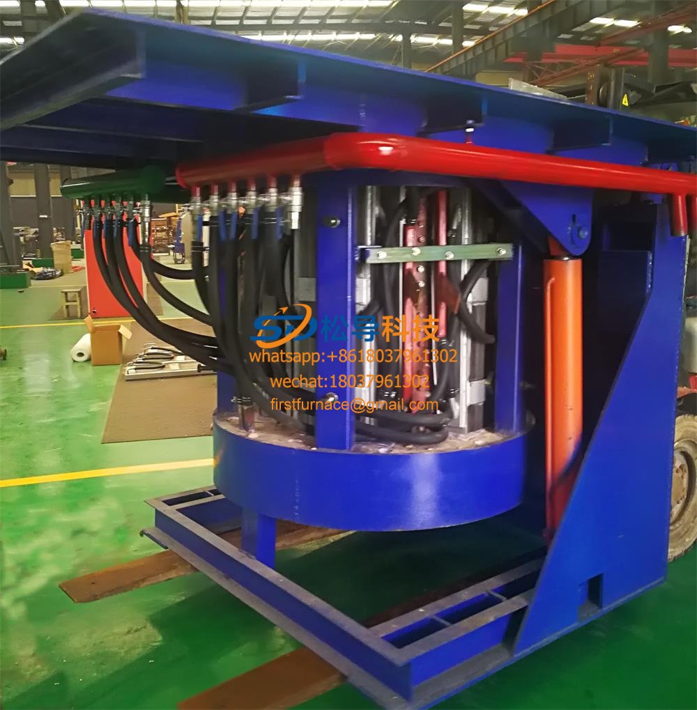
2T Series Intermediate Frequency Furnace
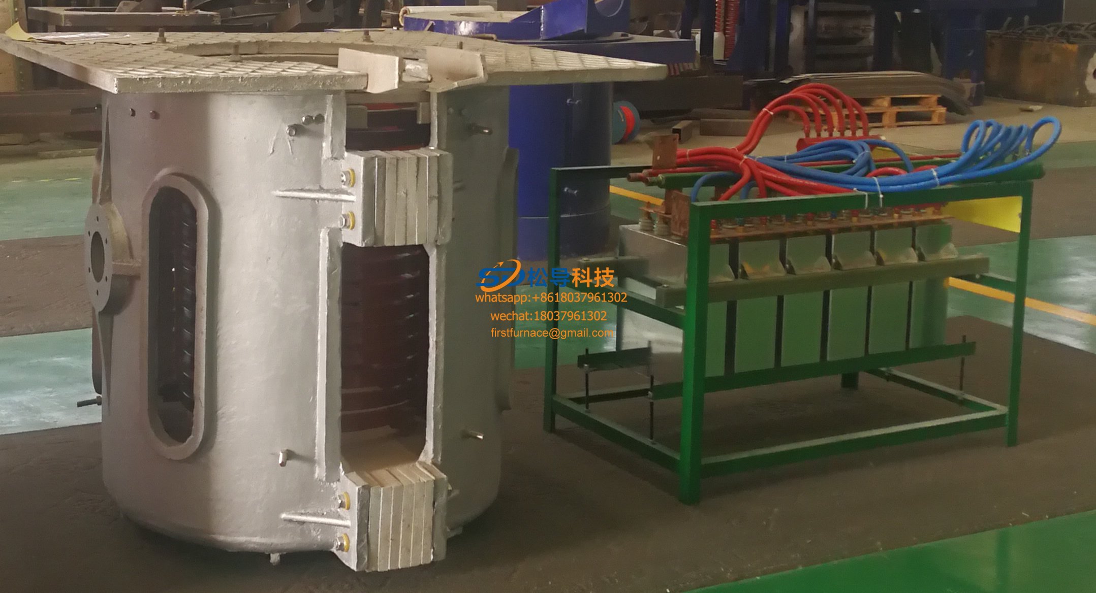
1T Series Intermediate Frequency Furnace
0.5T Series Intermediate Frequency Furna

0.25T Series Intermediate Frequency Furn
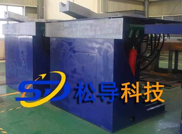
1T Parallel Intermediate Frequency Furna
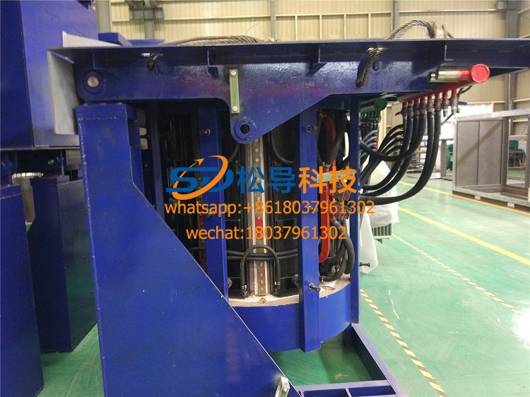
2T Parallel Intermediate Frequency Furna
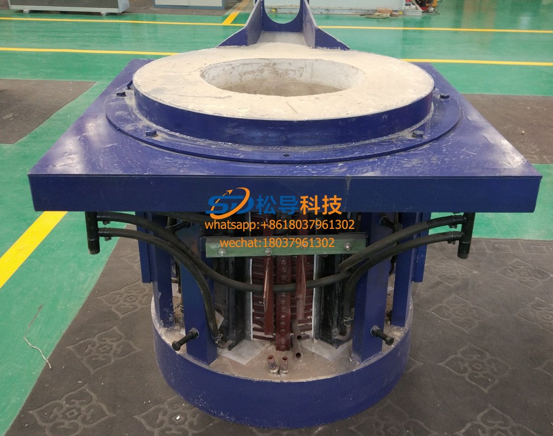
0.5T Parallel Intermediate Frequency Fur


