Sales hot line ( 24 hours service):+86 13015583380
E-Mail: firstfurnace@gmail.com
whatsapp:+86 13015583380
Adress: Luoxin Industrial Park, Luoyang, HenanLarge diameter steel pipe quen
Piston rod quenching and tempe
Grinding rod quenching and tem
High frequency induction heate
Quenching equipment for machin
Round steel end heating furnac
Steel pipe heat treatment prod
Square steel quenching and tem
Sucker rod quenching and tempe
Thickened petroleum steel pipe
Round steel quenching and temp
Steel pipe quenching and tempe
Steel plate quenching and temp
Induction Hardening Machine&nb
Flywheel ring gear high freque
Condition of intermediate frequency power rectifier circuit
Since the load of the intermediate frequency power supply rectifier circuit is an inverter, and the active power output by the inverter is provided by the rectifier circuit, this requires that the DC output voltage in the rectifier circuit can be continuously smoothed within a prescribed range. Adjustable.
In the IF power system, the load changes are very large, which requires the rectifier circuit to be able to automatically limit the output voltage. The usual method is to obtain the current and voltage signals at the load end and then change the rectification through the control signal. The phase shift control angle of the circuit, thereby completing the limiting current and limiting the voltage.
Rectifier circuits are usually required to protect the system from overvoltage and overcurrent, which requires phase shift control angle = 150 to form an active inverter. Since the output voltage adjustment range of the three-phase full-controlled bridge rectifier circuit is relatively large, the intermediate frequency power supply is mostly applied. In addition, the variation range of the phase shift control angle is relatively small, which is beneficial to the automatic adjustment of the system, and then reduces the burden caused by the DC filter link by outputting a higher voltage ripple frequency.
The control amount of the three-phase controlled rectifier circuit can be changed greatly and the output voltage ripple can be changed very small. The rectifier circuit is easy to filter and the time for controlling the hysteresis is short, so the three-phase controlled rectifier circuit is in the factory. Wide range of applications. When it comes to high-power power, we can weaken its coefficients by increasing its application efficiency.
When the inductance is large enough, the load current waveform is similar to a horizontal line. Single-phase controlled rectifier circuits are mostly used in low-power applications, but once the power exceeds 4 kW, the three-phase load cannot be balanced, so it is necessary to apply a three-phase bridge-type full-controlled rectifier circuit.
In this design, the intermediate frequency power supply uses a three-phase full-controlled bridge rectifier circuit, which can change the voltage value, and the amplitude is relatively large and the phase shift control angle does not change much, which facilitates the automatic adjustment of the system. Since the active power output from the inverter circuit is supplied by the rectifier circuit, it is required that the output voltage thereof can be continuously and smoothly adjusted within a prescribed range, thereby outputting the pulsating direct current. The load of the IF induction heating varies greatly, and the rectifier circuit should be able to automatically limit the output power, voltage and current, and can apply the rectifier circuit protection system.
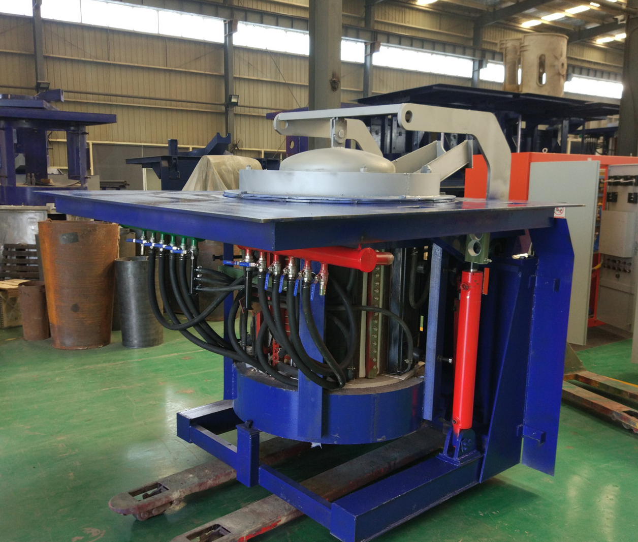
Iron induction furnace
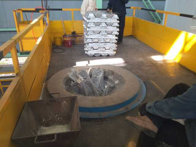
Aluminum melting furnace
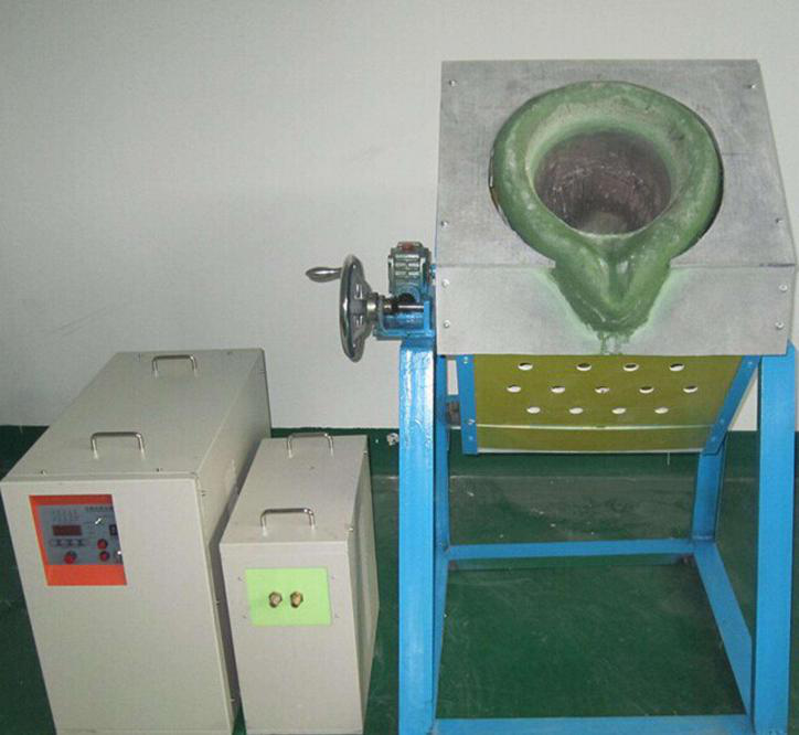
Copper melting furnace
Small steel melting furnace
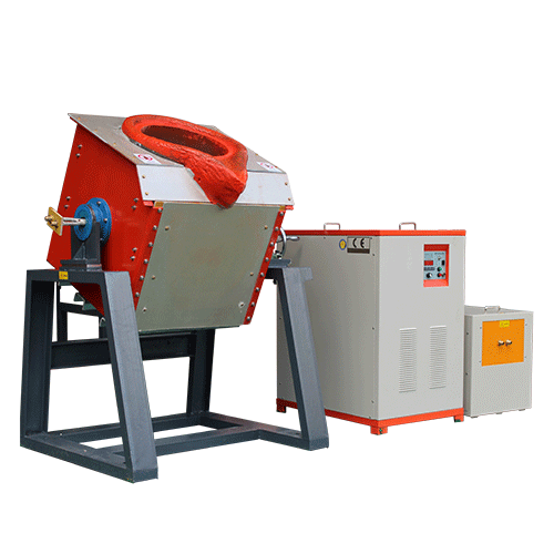
Small induction melting furnace
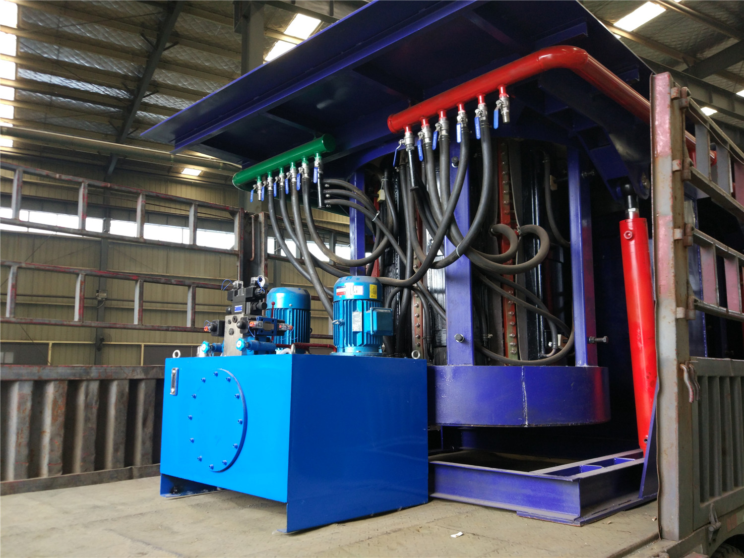
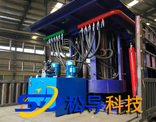
Induction iron furnace
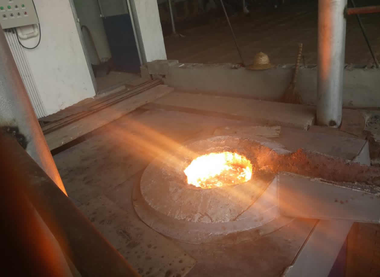
3T intermediate frequency iron melting f
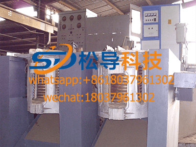
0.25T Intermediate Frequency Furnace
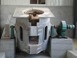
0.5T Intermediate Frequency Furnace
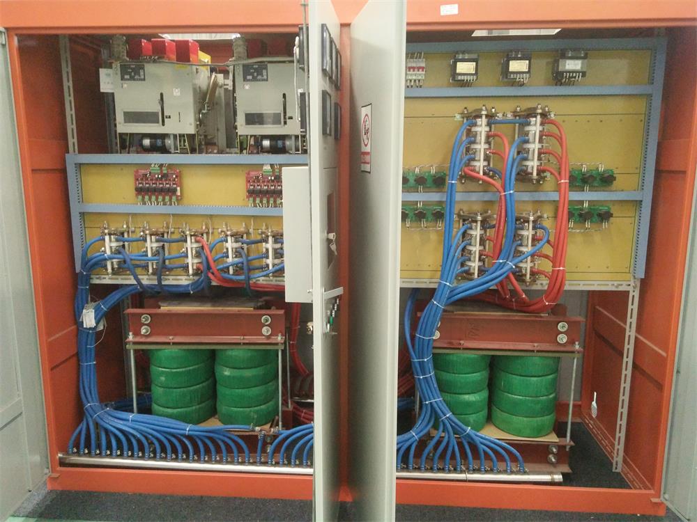
Medium Frequency Furnace

2T Induction Melting Furnace
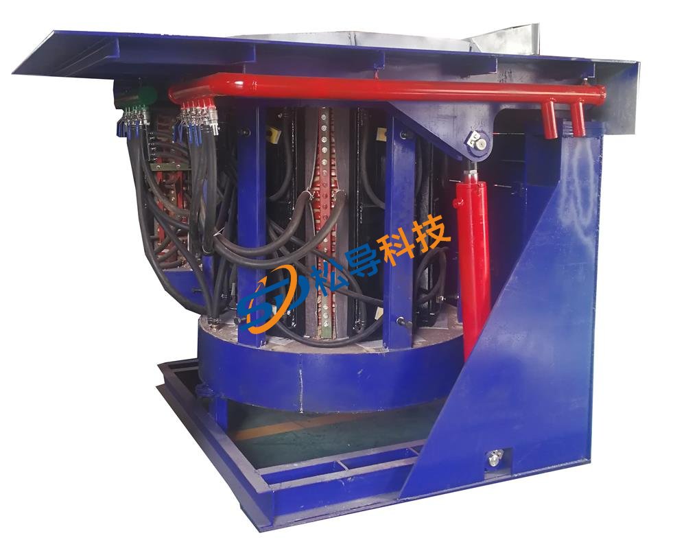
1T Induction Melting Furnace
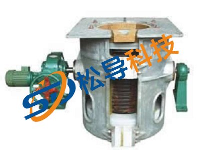
500kg Induction Melting Furnace
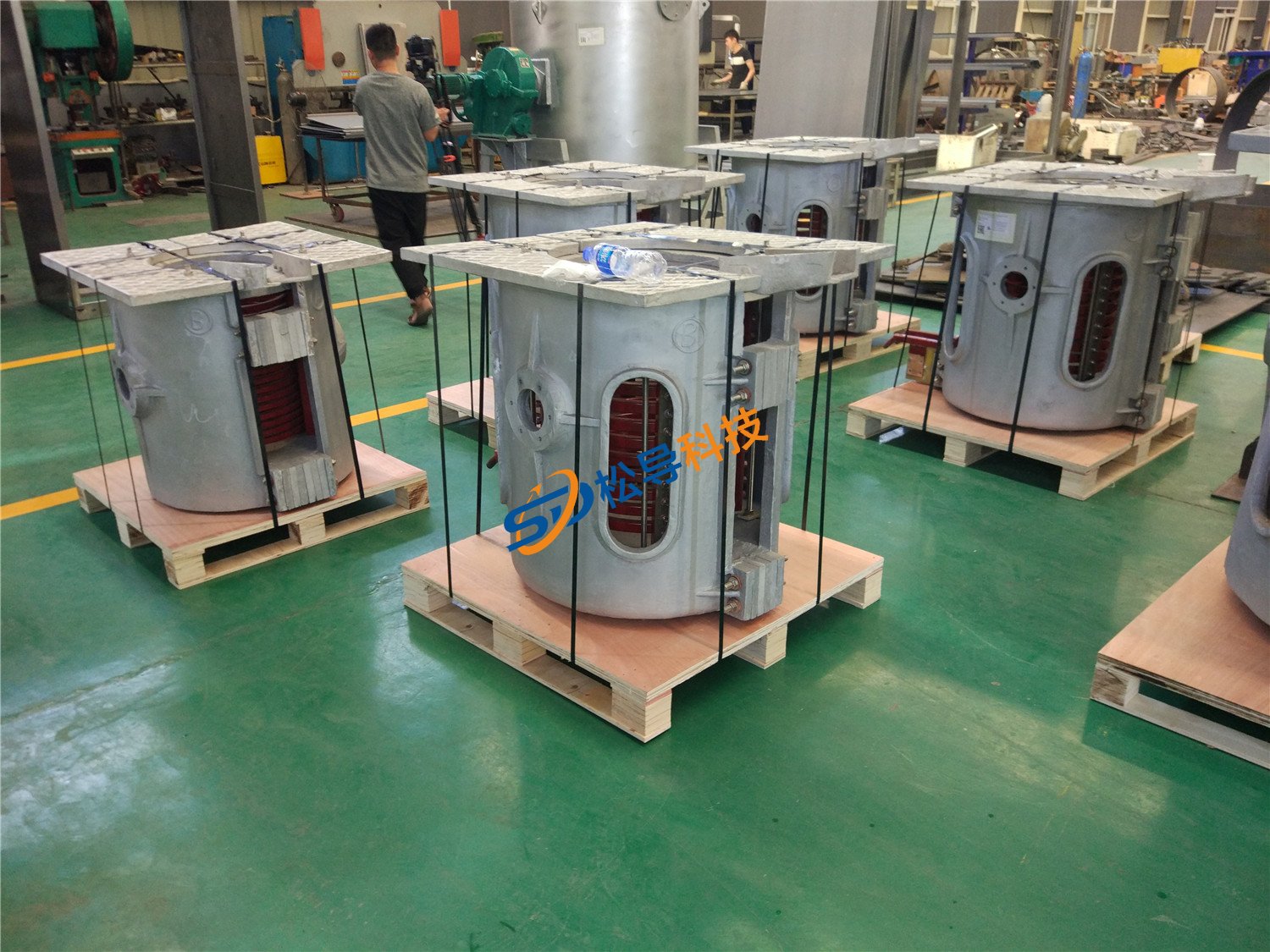
250kg Induction Melting Furnace
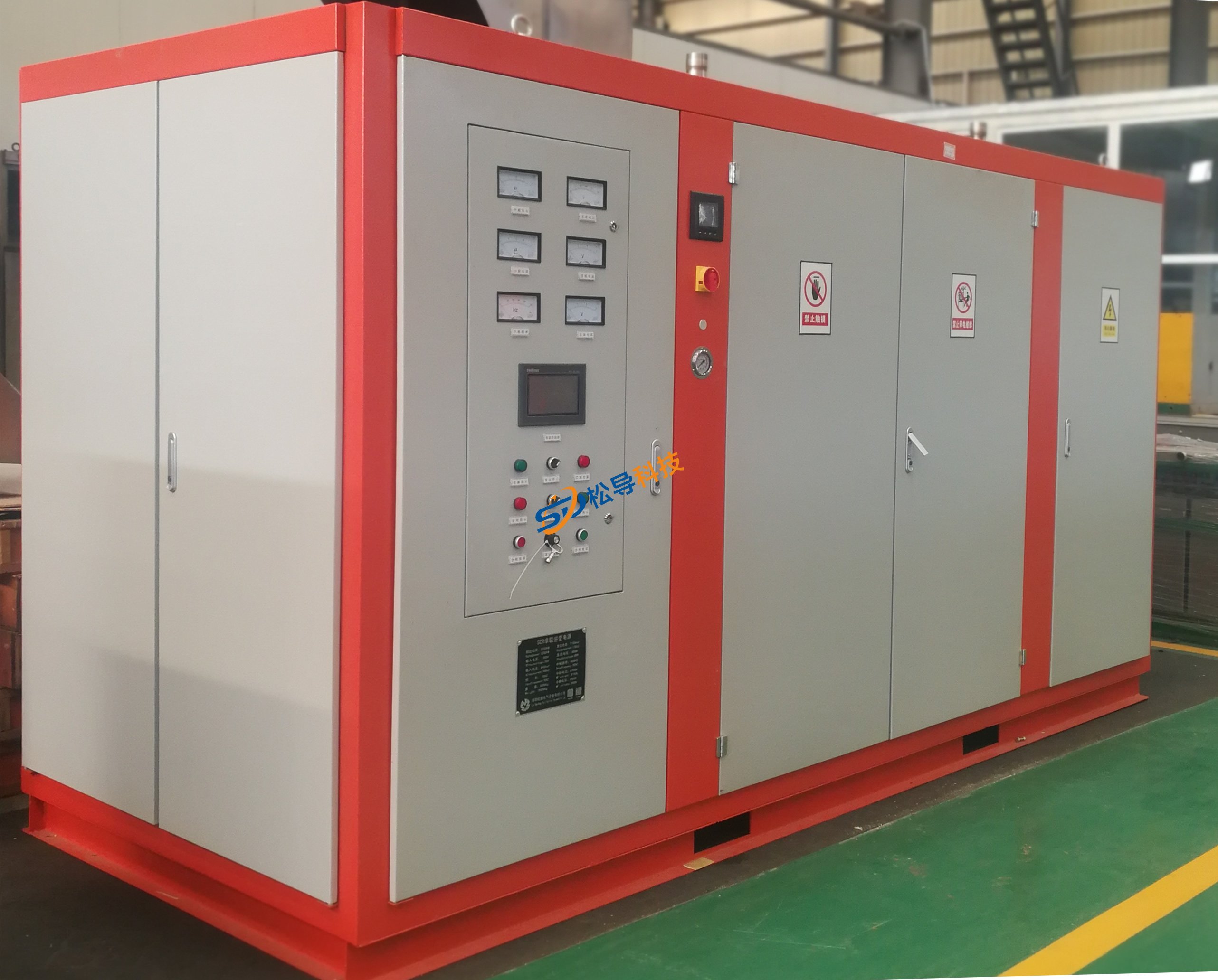
Induction Melting Furnace
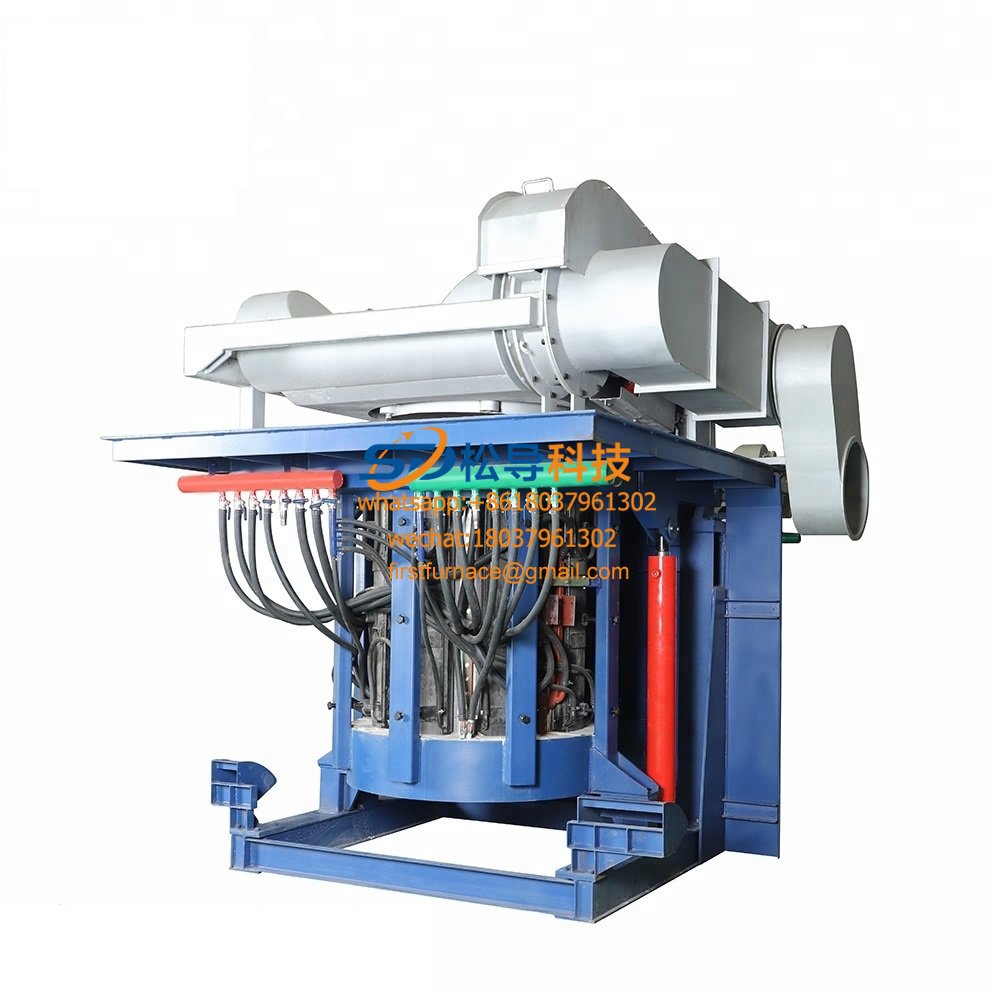
3 T Induction Melting Furnace
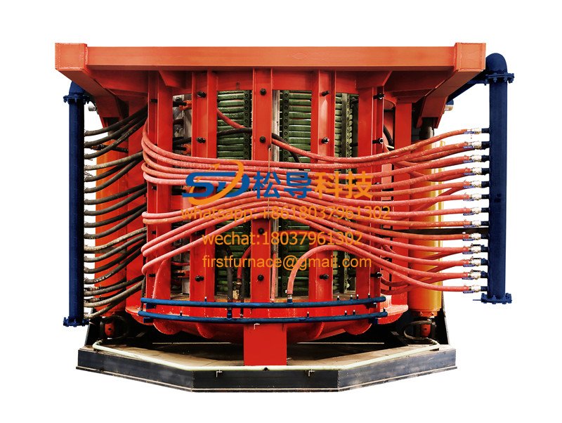
5T Induction Melting Furnace
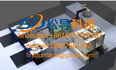
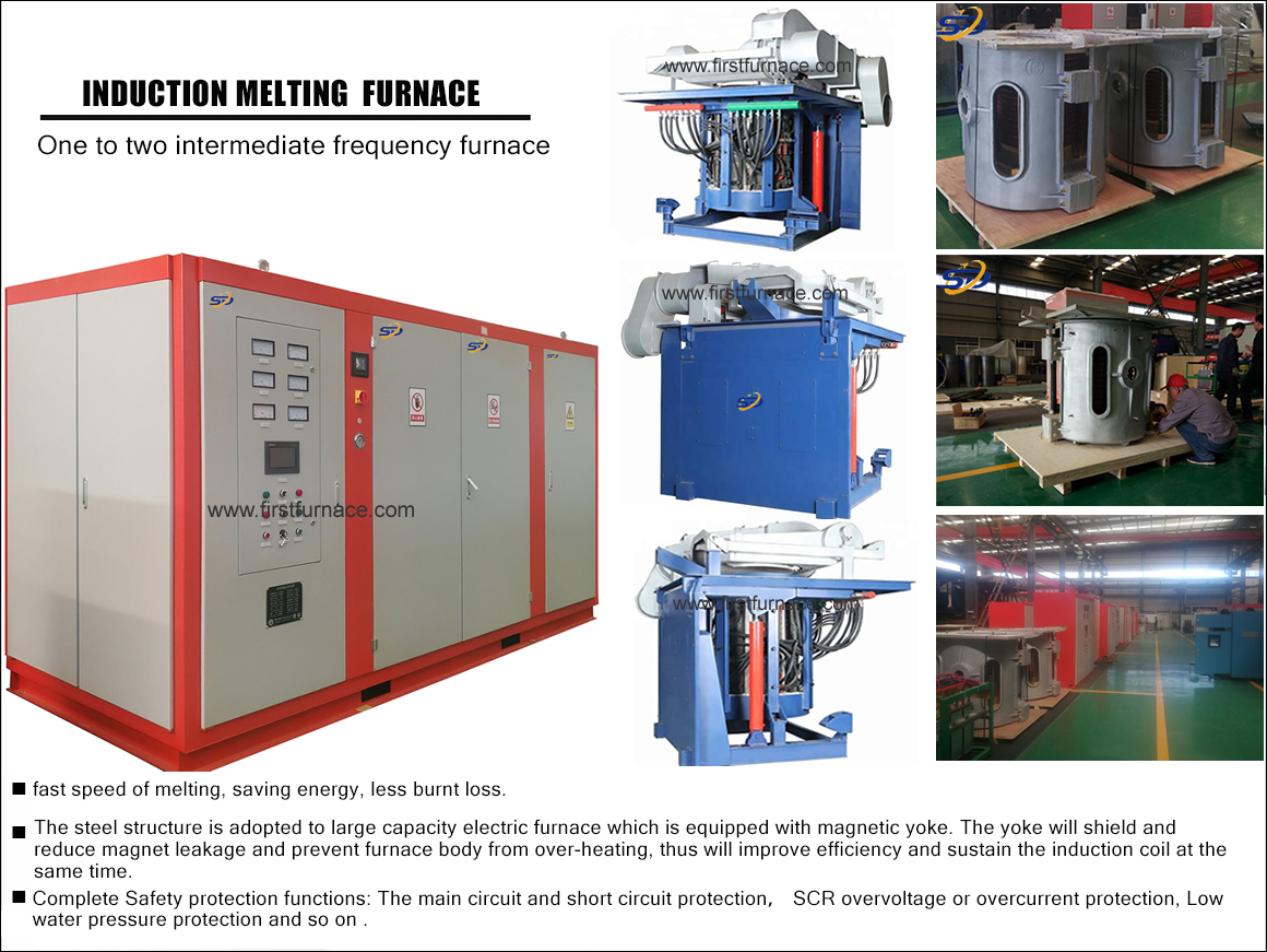
1T One Belt Two Intermediate Frequency F

5T One Belt Two Intermediate Frequency F
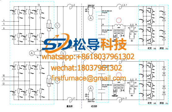
3T One Belt Two Intermediate Frequency F
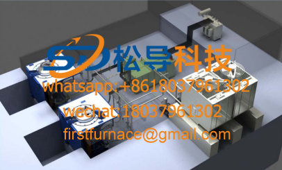
2T One Belt Two Intermediate Frequency F
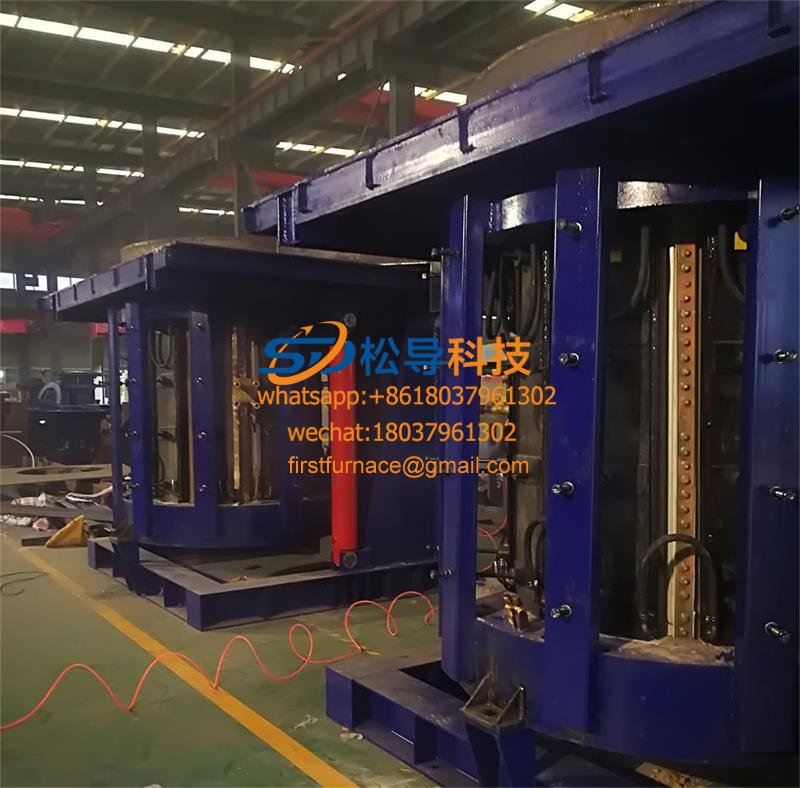
5T Parallel Intermediate Frequency Furna
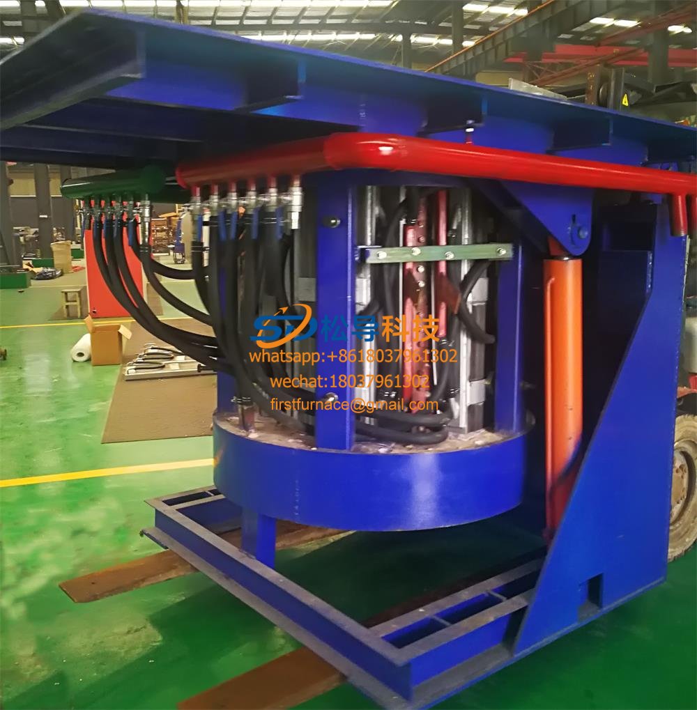
5T Intermediate Frequency Furnace

5T Series Intermediate Frequency Furnace
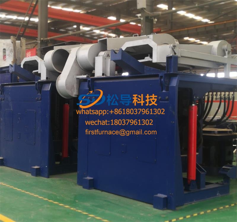
3T Series Intermediate Frequency Furnace
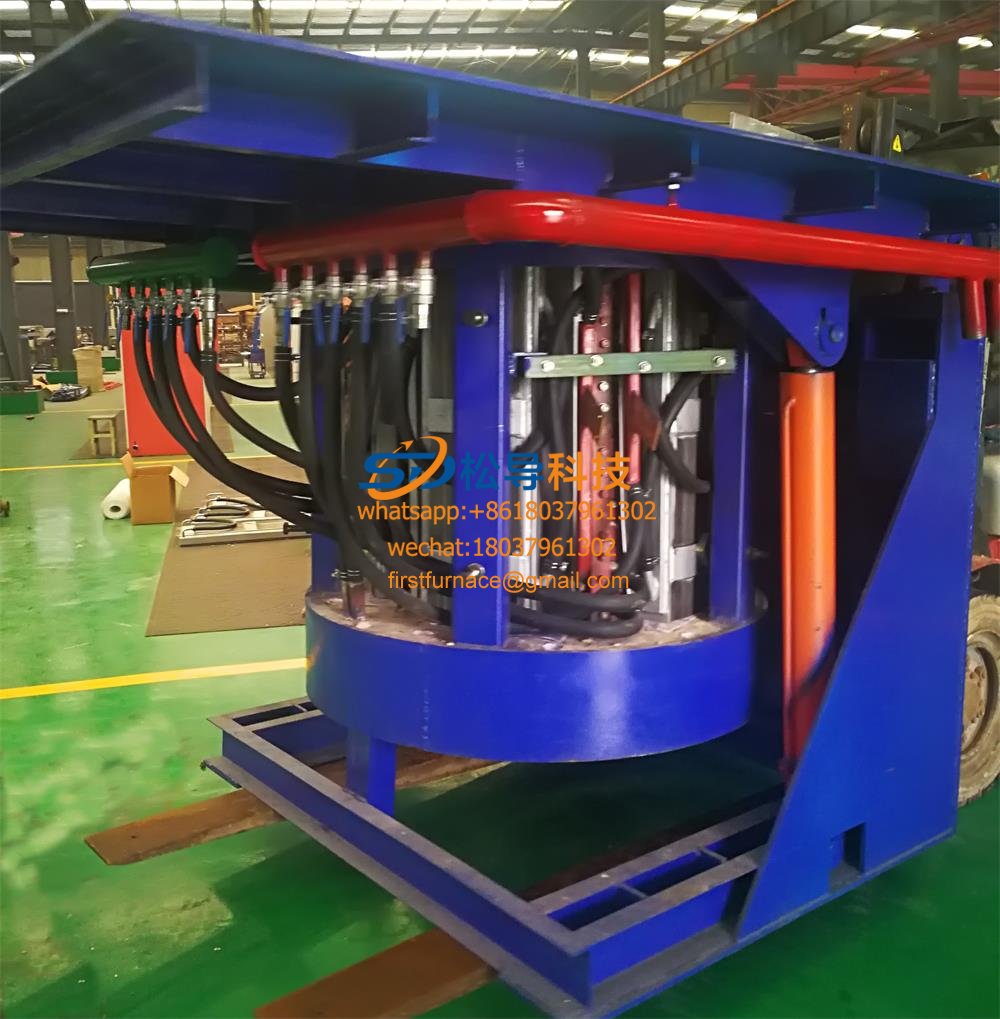
2T Series Intermediate Frequency Furnace
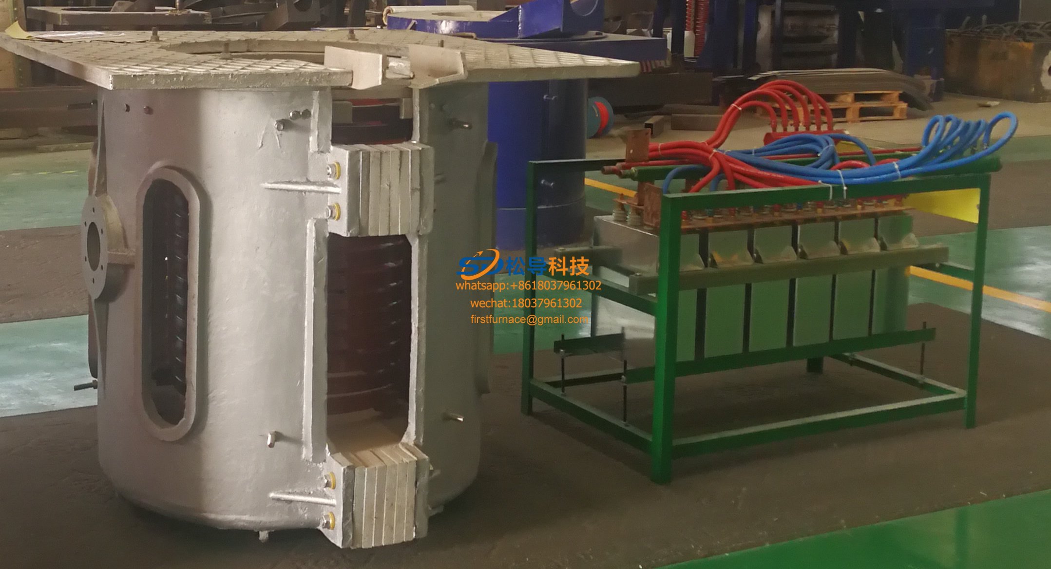
1T Series Intermediate Frequency Furnace
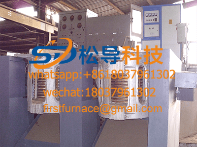
0.5T Series Intermediate Frequency Furna

0.25T Series Intermediate Frequency Furn
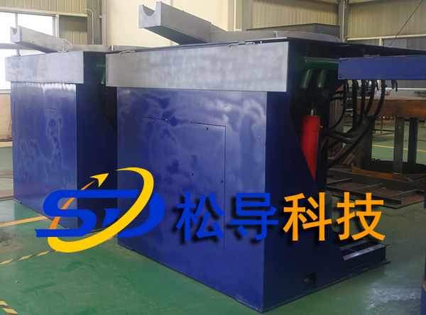
1T Parallel Intermediate Frequency Furna
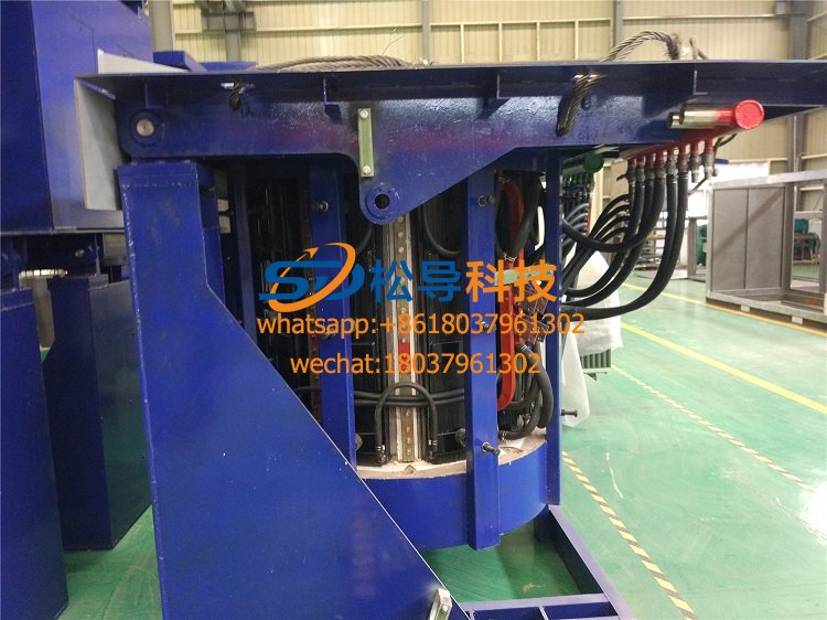
2T Parallel Intermediate Frequency Furna
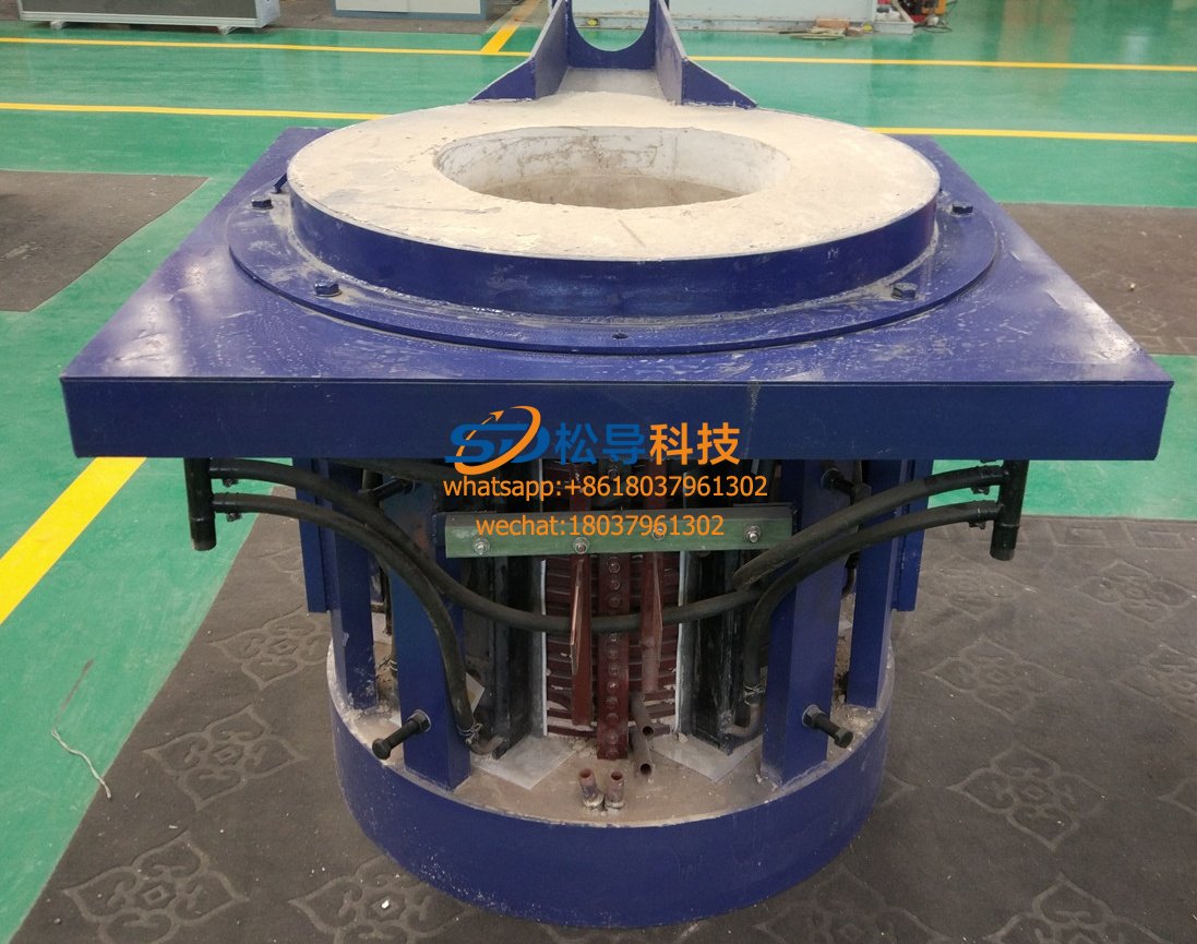
0.5T Parallel Intermediate Frequency Fur


