Sales hot line ( 24 hours service):+86 13015583380
E-Mail: firstfurnace@gmail.com
whatsapp:+86 13015583380
Adress: Luoxin Industrial Park, Luoyang, HenanLarge diameter steel pipe quen
Piston rod quenching and tempe
Grinding rod quenching and tem
High frequency induction heate
Quenching equipment for machin
Round steel end heating furnac
Steel pipe heat treatment prod
Square steel quenching and tem
Sucker rod quenching and tempe
Thickened petroleum steel pipe
Round steel quenching and temp
Steel pipe quenching and tempe
Steel plate quenching and temp
Induction Hardening Machine&nb
Flywheel ring gear high freque
At present , the bearing steel heated in the induction heating furnace is generally 800-1700 ℃. It is difficult for ordinary equipment to maintain long-term working conditions. It is difficult for equipment such as fan structures to reach the temperature required by the induction heating furnace . New materials or new materials need to be developed. way to induction furnace heat, induction furnace no cooling device or substance within the furnace, the heat sink current is limited only heat the air in the periphery of the furnace, it is difficult to protect the integrity of the furnace itself, even when severe that The furnace itself overheated and burst. Therefore, at present, it continues to be able to enter the furnace itself to cool down, and without delaying the operation of the equipment, and is fast, efficient and durable.
The following technical solution is provided: An induction heating furnace cooling device includes an induction heating furnace , a water delivery pipe, and a water storage tank. The water storage tank is divided into a hot water tank and a heat storage tank by installing a partition plate with a perforated hole inside. Cold water tank, round furnace groove is installed on the upper part of the water tank, the induction heating furnace is clamped in the furnace groove, the inner wall of the induction heating furnace is looped around the water conveyance pipeline, and the water inlet of the water pipeline is set in the cold water reservoir in the reservoir. The water outlet of the road is set in the hot water tank in the storage tank. A cold water pump is set at the bottom of the cold water tank, and the cold water pump is connected to the water inlet of the water delivery pipe. A cooling tower is set above the storage tank. Water pipes, cooling tower outlet pipes and cooling tower inlet pipes are all plugged into the cold pool. A steam outlet is set on the top of the reservoir. A temperature sensor is installed at the top edge of the reservoir, and the temperature sensor is electrically connected and installed
Lights on the side wall of the cistern. The upper side wall of the reservoir is provided with a water inlet valve, and the lower side wall of the reservoir is provided with a water outlet valve.
Compared with the prior art, the utility model has the beneficial effect that the equipment uses water circulation to carry out the furnace body itself.
The temperature is reduced, the temperature-reducing materials are continuously transported and replaced, and the temperature is continuously reduced. The water is used to enter the interior of the furnace, and the temperature is reduced in the body. The effect is better and faster.
BRIEF DESCRIPTION OF THE DRAWINGS
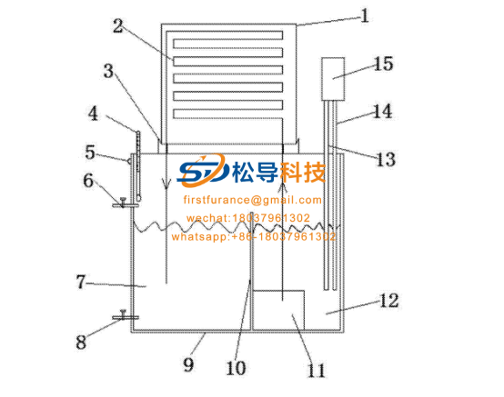
1 induction heating furnace , 2 water pipeline, 3 furnace tank, 4 temperature sensor, 5 indicator lights, 6 water inlet valve, 7 hot water
Pool, 8 water outlet valves, 9 reservoirs, 10 compartment plates, 11 cold water pumps, 12 cold pools, 13 cooling tower outlet pipes, 14 cooling tower inlet pipes, 15 cooling towers, 16 water holes, and 17 steam outlets.
Specific improvement technical solutions
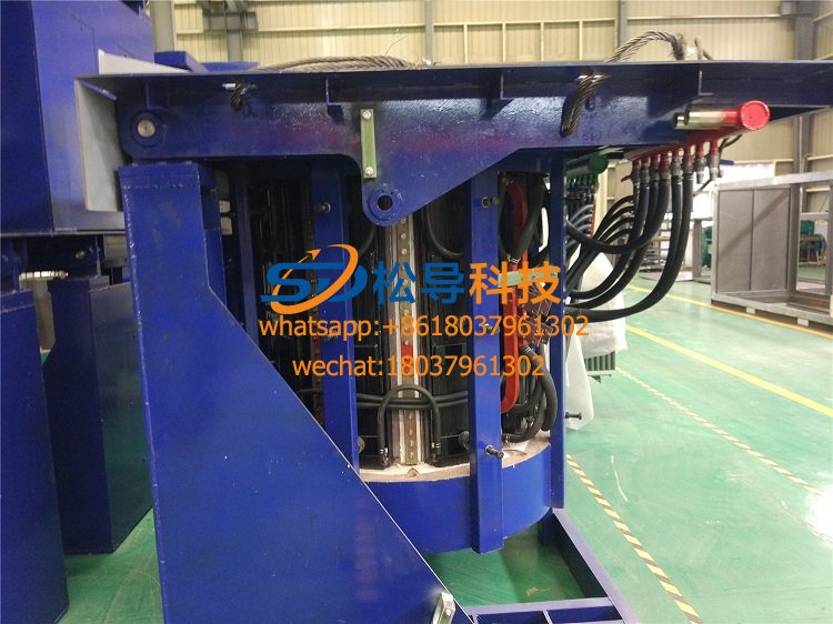
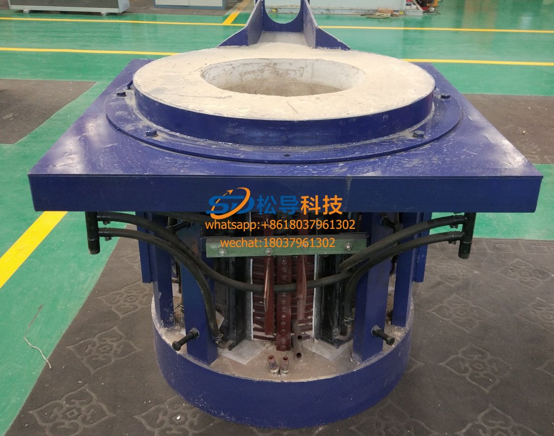
Induction furnace heat dissipation device comprises a medium frequency induction furnace L , water pipeline 2 and the reservoir 9 , the reservoir 9 through the permeable inner mounting holes with 16 compartments of the pool plate 10 , so that the reservoir 7 into the hot water tank 7 and a cold water tank 12 , the reservoir 9 at the top is provided the steam discharge port 17 , the reservoir 9 at the top edge of the set temperature sensing meter 4 , the temperature sensing meter 4 is electrically connected and mounted in the reservoir 9 side wall lights, water pool 9upper sidewall disposed inlet valve 6 , the reservoir 9 a lower outlet sidewall valve 8 , the reservoir 9 the upper mounting groove circular furnace 3 , an induction heating furnace l snap groove furnace 3 within, induction furnace l The inner wall is looped around the water conveying pipeline 2 , and the water inlet of the water conveying pipeline 2 is arranged in the cold pool12 in the reservoir 9 , and the water outlet of the water conveying pipeline 2 is arranged in the hot pool 7 in the reservoir 9 and the cold pool 12 A cold water pump II is set at the bottom , and the cold water pump II is connected to the water inlet of the water delivery pipeline 2. A cooling tower 15 is provided above the reservoir 9; the bottom of the cooling tower 15 is connected to the cooling tower outlet pipe 13 and the cooling tower inlet pipe 14 , and the cooling tower outlet pipe 13 The top of the cooling tower water inlet pipe 14 is inserted into the cold pool 12 .
Working principle: A heat sink of an induction heating furnace is operated by a cold water pump II , so that the water in the cold pool 12
By body water pipeline 2 the inlet into the furnace induction l water inside the pipeline 2 for cooling by water pipeline 2 the outlet into the hot water tank 7 , the heat sink 7 inside the hot water tank via a separator plate 10 permeable holes 16 It enters the cold pool 12 for neutralization, and enters the cooling tower 15 through the cooling tower water inlet pipe 14 for cooling, and is sent to the cold pool through the cooling tower water outlet pipe 13 for the next cycle.
induction heating furnace:http://www.songdaokeji.com
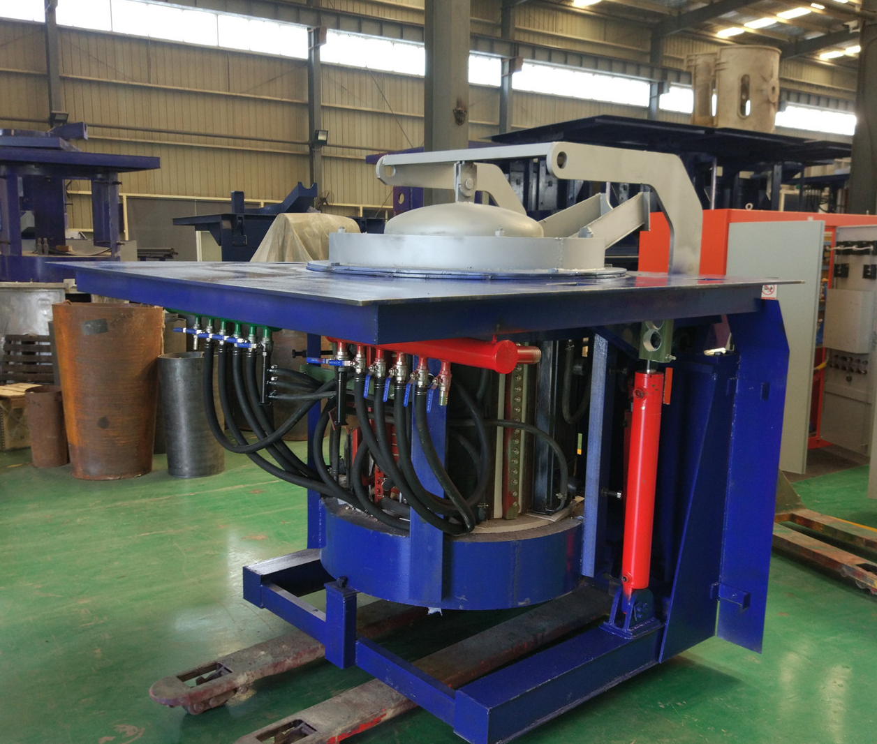
Iron induction furnace
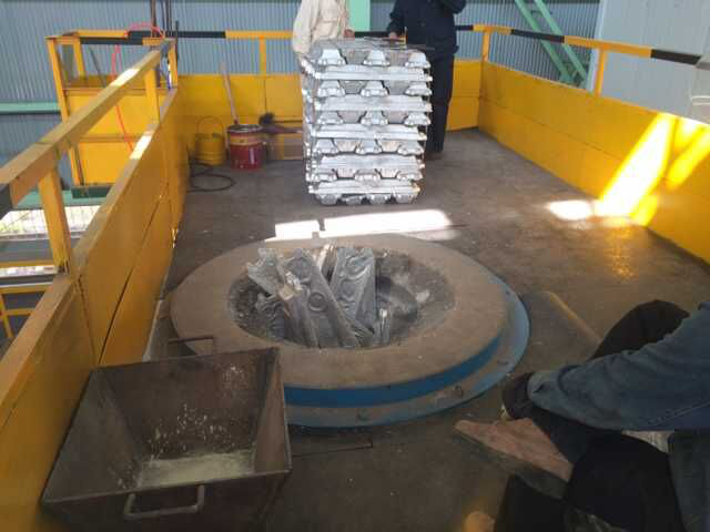
Aluminum melting furnace
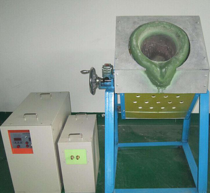
Copper melting furnace
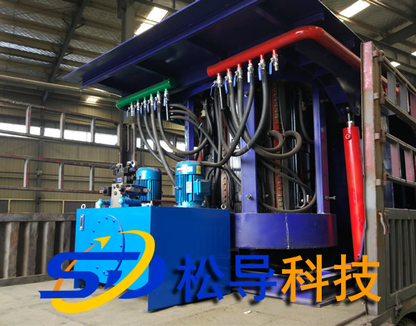
Small steel melting furnace
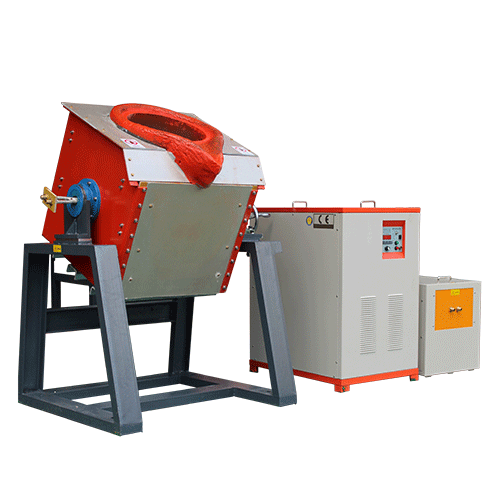
Small induction melting furnace
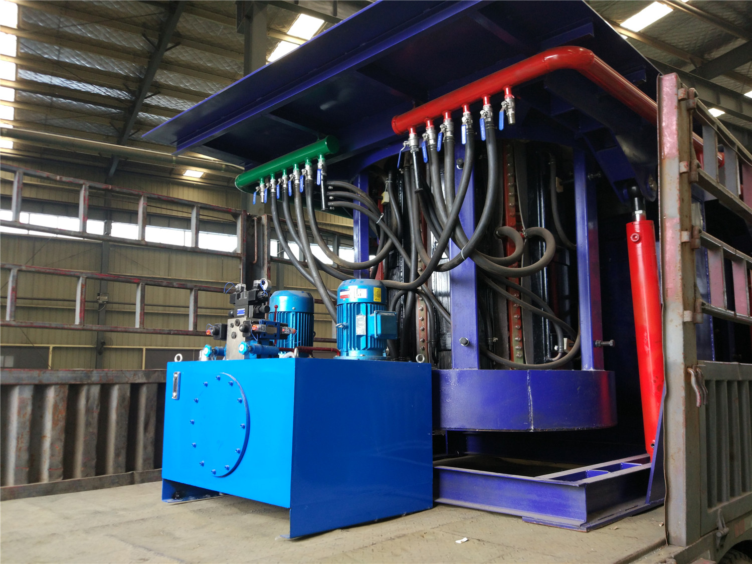
Induction iron furnace
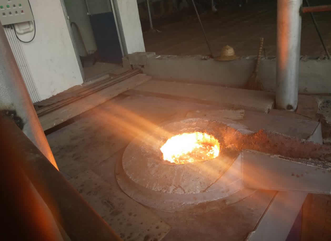
3T intermediate frequency iron melting f
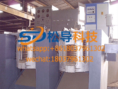
0.25T Intermediate Frequency Furnace
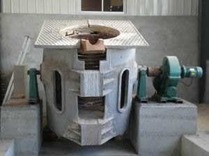
0.5T Intermediate Frequency Furnace
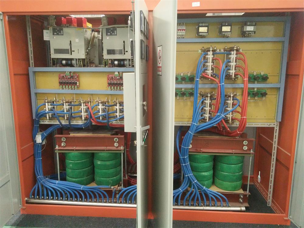
Medium Frequency Furnace

2T Induction Melting Furnace
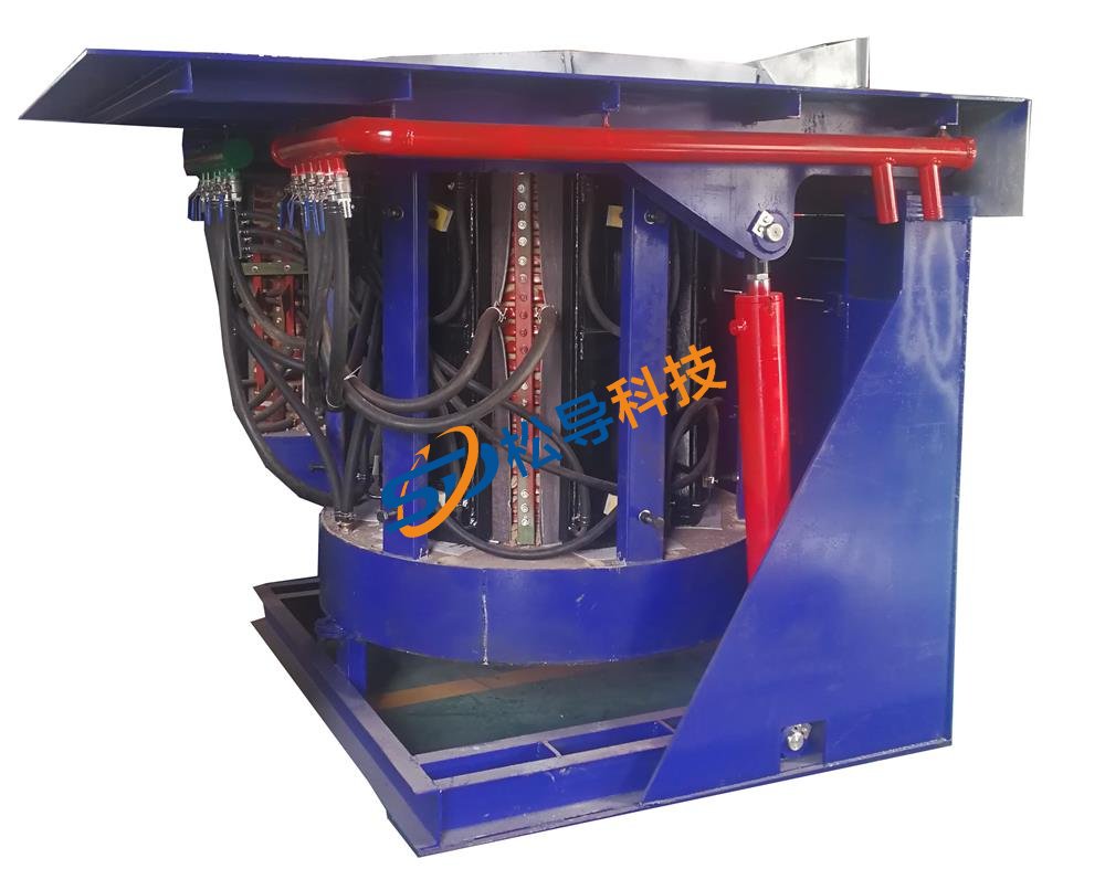
1T Induction Melting Furnace
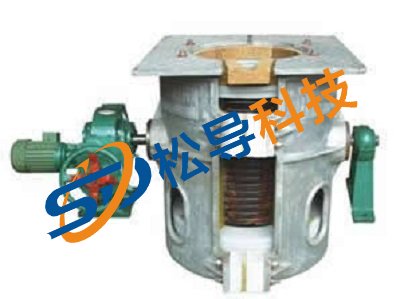
500kg Induction Melting Furnace
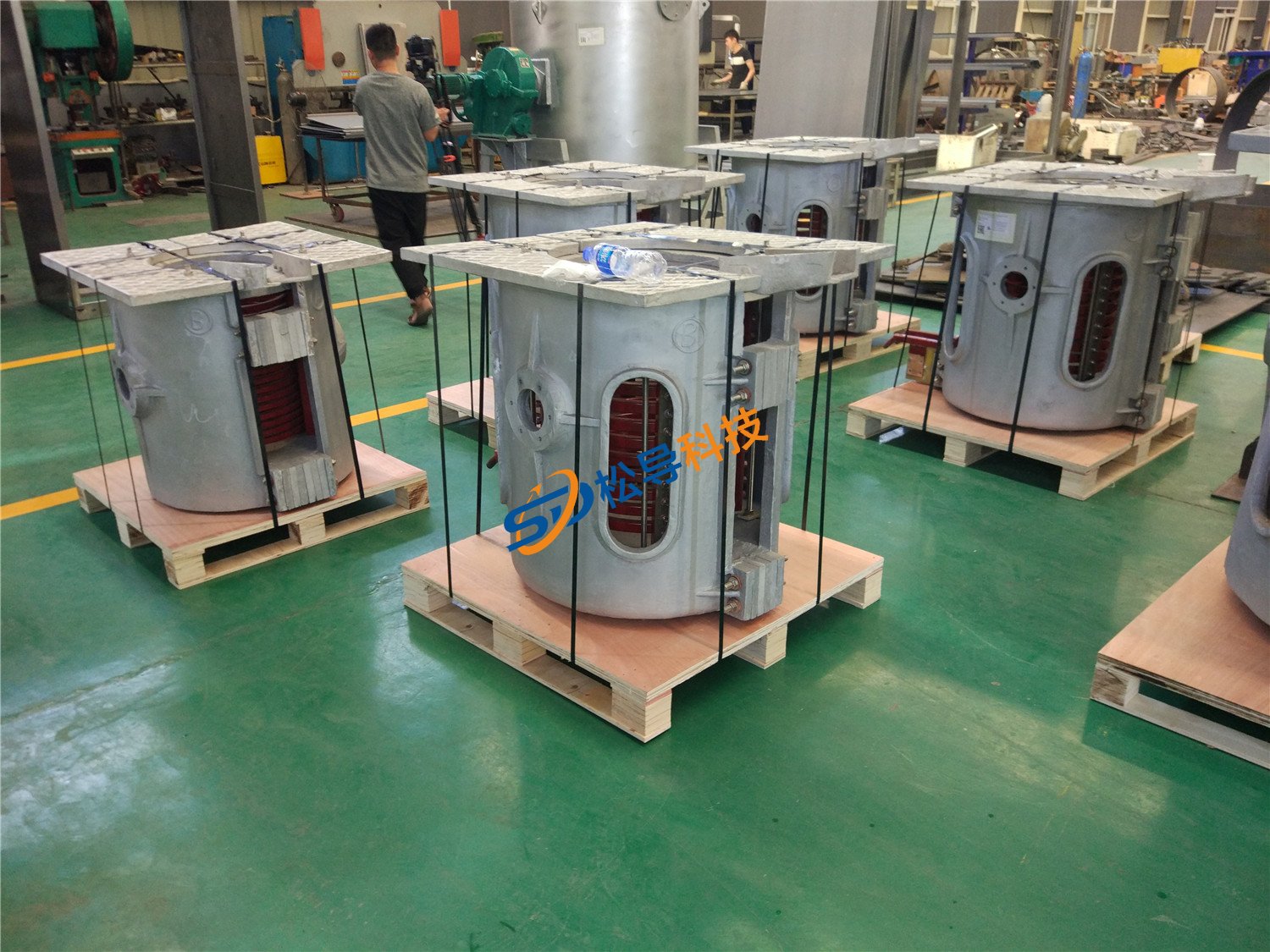
250kg Induction Melting Furnace
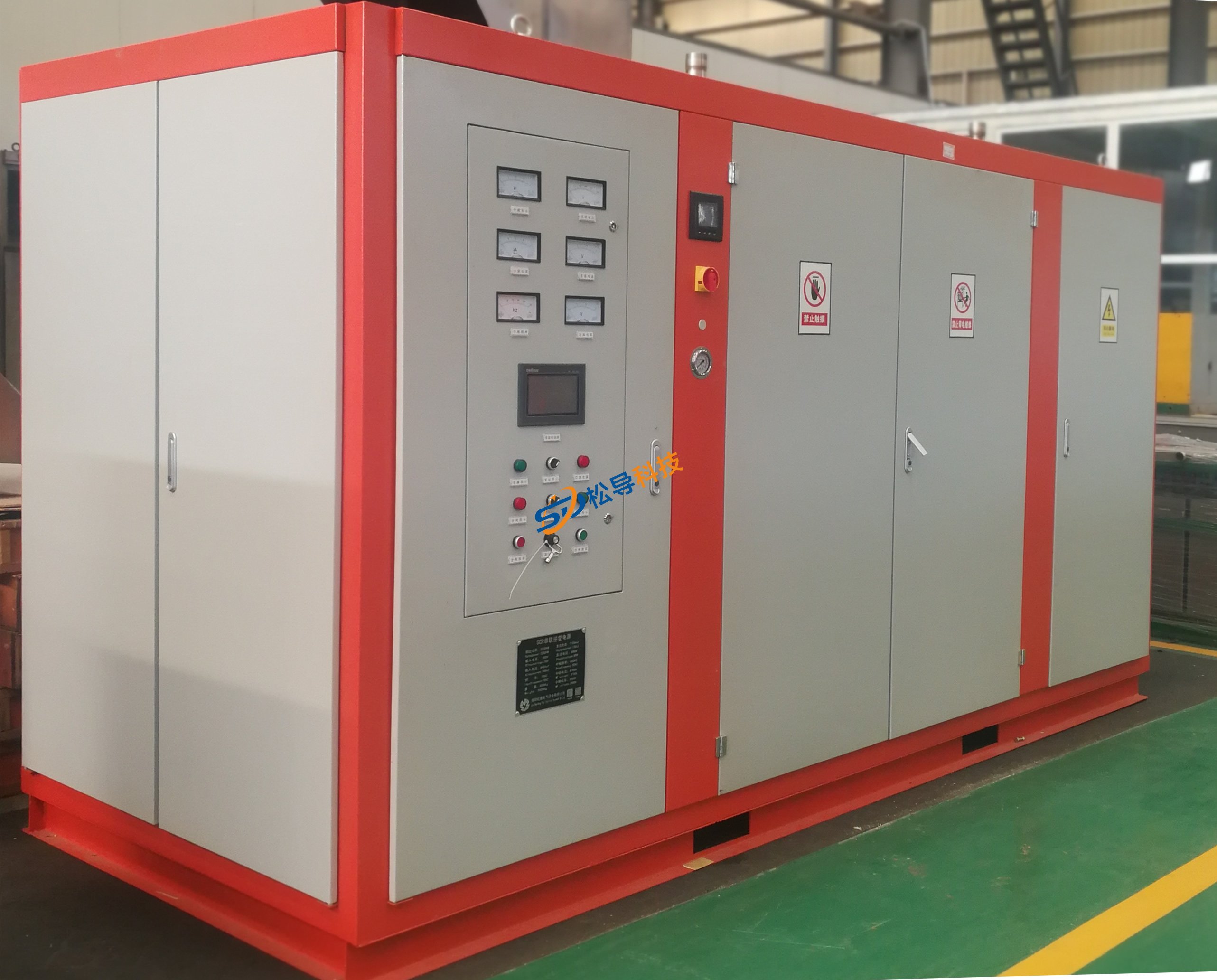
Induction Melting Furnace
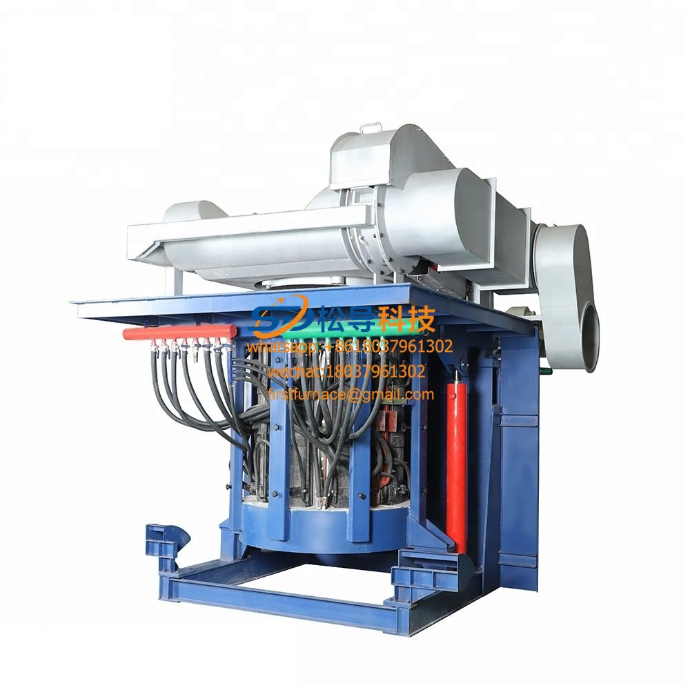
3 T Induction Melting Furnace
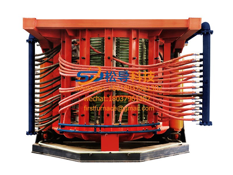
5T Induction Melting Furnace
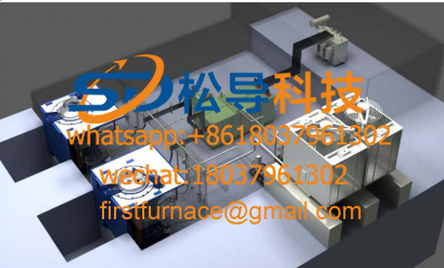
1T One Belt Two Intermediate Frequency F

5T One Belt Two Intermediate Frequency F
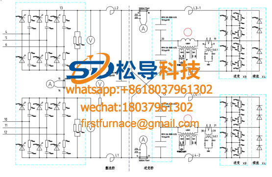
3T One Belt Two Intermediate Frequency F
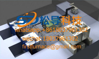
2T One Belt Two Intermediate Frequency F
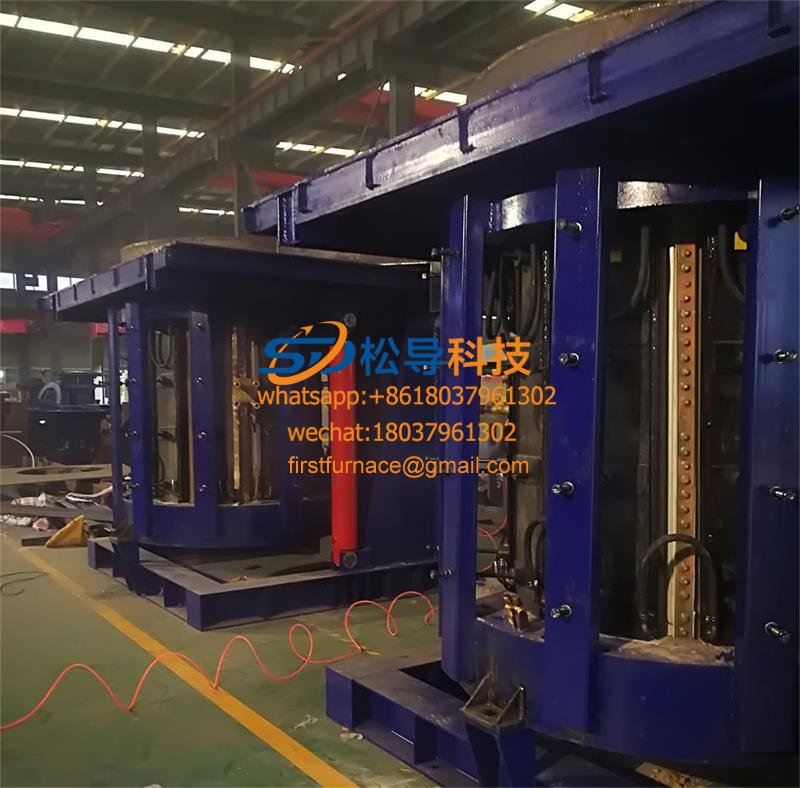
5T Parallel Intermediate Frequency Furna
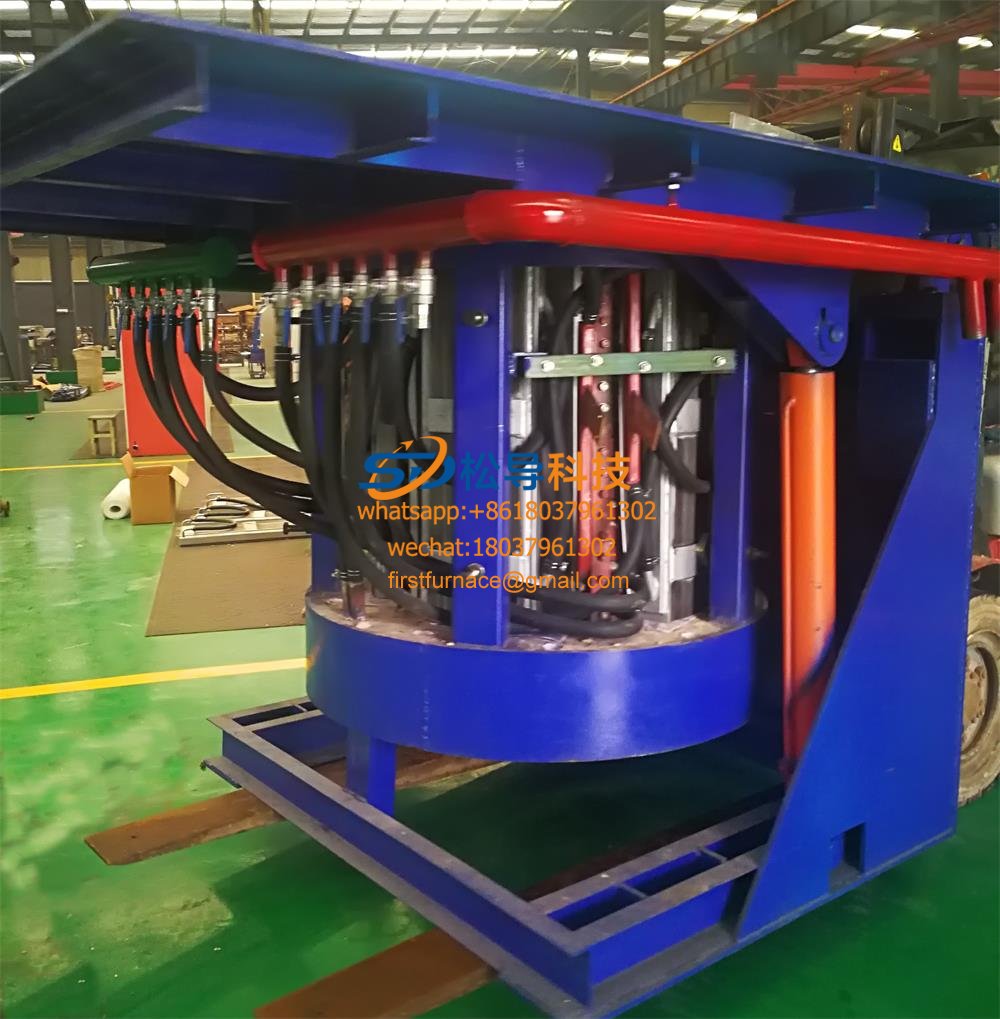
5T Intermediate Frequency Furnace

5T Series Intermediate Frequency Furnace
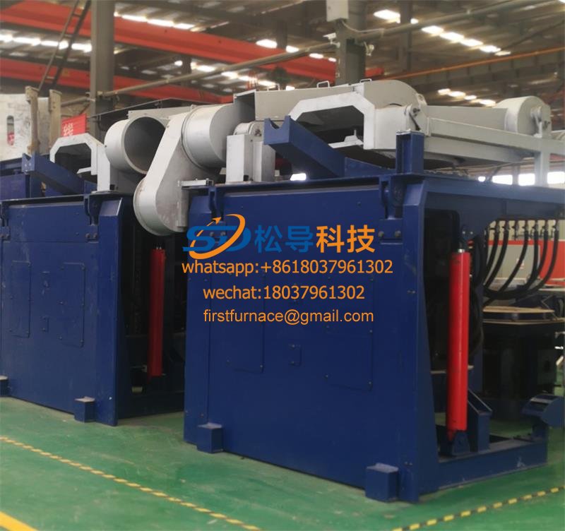
3T Series Intermediate Frequency Furnace
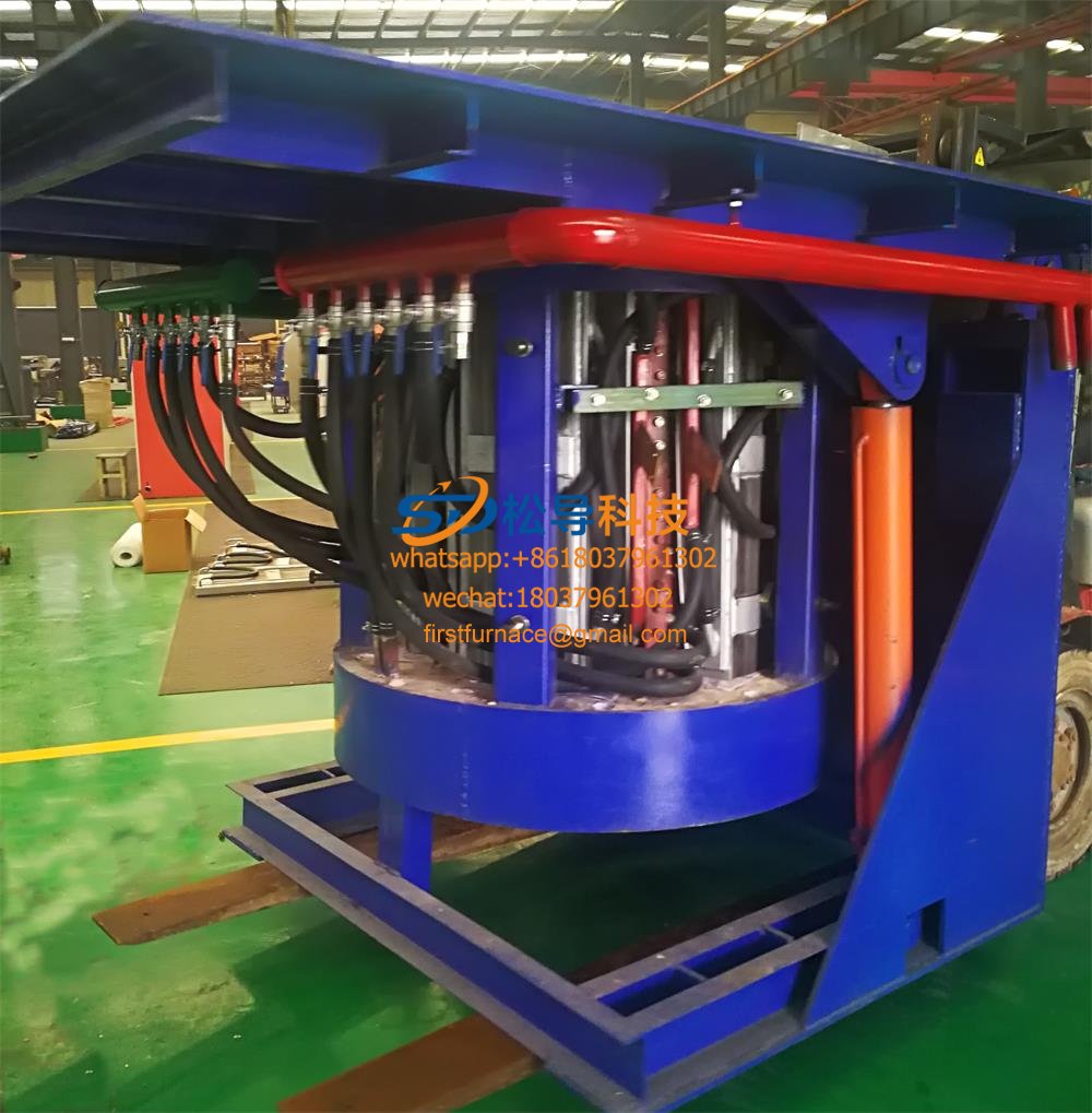
2T Series Intermediate Frequency Furnace
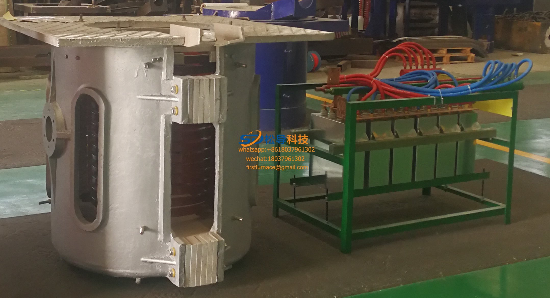
1T Series Intermediate Frequency Furnace
0.5T Series Intermediate Frequency Furna

0.25T Series Intermediate Frequency Furn
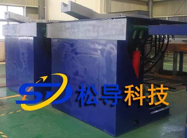
1T Parallel Intermediate Frequency Furna
2T Parallel Intermediate Frequency Furna
0.5T Parallel Intermediate Frequency Fur


