Sales hot line ( 24 hours service):+86 13015583380
E-Mail: firstfurnace@gmail.com
whatsapp:+86 13015583380
Adress: Luoxin Industrial Park, Luoyang, HenanLarge diameter steel pipe quen
Piston rod quenching and tempe
Grinding rod quenching and tem
High frequency induction heate
Quenching equipment for machin
Round steel end heating furnac
Steel pipe heat treatment prod
Square steel quenching and tem
Sucker rod quenching and tempe
Thickened petroleum steel pipe
Round steel quenching and temp
Steel pipe quenching and tempe
Steel plate quenching and temp
Induction Hardening Machine&nb
Flywheel ring gear high freque
Temperature control device and method for moving blanks in intermediate frequency diathermy furnace
Technical field
The invention relates to a temperature control device and method for a blank preheating process in the forging field, in particular to an intermediate frequency transparent
The temperature control device and method for moving the billet in the heating furnace, in other words, is a kind of diathermy for the moving billet in the intermediate frequency diathermy furnace
Device and method for process temperature control.
Background technique
The intermediate frequency diathermic furnace has high thermal efficiency, short heating time, less oxidation and decarburization on the surface of the heated workpiece, and less distortion of the workpiece.
It has the characteristics of good controllability, easy realization of mechanization and automation, and has been widely used in the forging field. Due to the forged billet
The temperature value of the material and whether the internal and external temperatures are uniform directly affect the structure and mechanical properties of the forging, so the intermediate frequency diathermy furnace is used to diather
(I.e. through heating) of the billet requires that the temperature after diathermy reach the design requirement and the temperature difference between the inside and outside of the billet is the smallest (ie the temperature is equal
Homogenization).
The temperature value of the billet after diathermy and whether the inner and outer temperatures of the billet are uniform are determined by the residence time of the billet in the furnace body,
It is determined by three parameters: the diathermic power density of the blank and the diathermic frequency of the intermediate frequency diathermy furnace. When the intermediate frequency diathermy furnace is heated, the billet
If the material stays in the furnace for too long, it will cause the thickening of the surface oxide layer and even over-burning, resulting in the strength and toughness of the forging part.
Deterioration, thus shortening the service life of the forging; if the residence time of the blank in the furnace is too short, its temperature is too low and the forging cannot be smoothly performed.
Shorten the service life of forging equipment. The heat transmission power density of the blank refers to the heat transmission power per unit area of the blank, which is determined by
The output power of the intermediate frequency diathermic furnace is determined, and the diathermic power density of the billet depends on the melting speed of the billet.
Too much rate density will cause the surface of the workpiece to overheat or even melt; if the diathermic power density is too small, the heating time of the workpiece will be too long
Long, eventually leading to low production efficiency. The heat transmission frequency of the intermediate frequency diathermy furnace determines the heat transmission depth of the blank, and the heat transmission frequency is too high.
High, it will make the heating depth shallow, and eventually lead to excessive temperature difference between the inside and outside of the blank; while the frequency of diathermy is too low, although it can reduce the internal temperature.
The external temperature difference will increase the total current and copper loss of the heating coil, which will eventually lead to a decrease in electrical efficiency and an increase in energy consumption. While
The temperature control of the moving billet in the frequency diathermic furnace is to adjust the residence time of the billet in the furnace body and the output of the intermediate frequency diathermic furnace.
The three parameters of power and the diathermic frequency of the intermediate frequency diathermic furnace make the temperature of the diathermy billet reach the design requirement value and the temperature
Homogenization ensures that the structure and mechanical properties of the blank meet the forging requirements.
However, it is difficult for the temperature control equipment and method of the prior art to accurately and real-time temperature control the intermediate frequency diathermy furnace. The specific reasons are as follows:
under:
The prior art temperature control devices include non-contact type and contact type. The non-contact temperature control device measures the radiation of the blank
According to the corresponding relationship between the thermal radiation energy and the temperature, the temperature value is converted. However, when the furnace body is heated, a large amount of energy is generated in the furnace cavity.
The amount of smoke and dust interferes with the process of receiving radiant energy by the temperature control device, so the temperature measurement effect of the non-contact temperature control device is very good.
The temperature acquisition accuracy is low, and, more importantly, due to the limitation of the narrow space in the furnace cavity, the temperature measurement device cannot follow
For the follow-up of the blank, only the temperature values at the entrance and exit of the furnace cavity can be measured, so the temperature collection range is small. Contact temperature control equipment
The thermocouple type like a protective tube means that a protective sleeve of ceramic material is set outside the thermocouple, and the blank is in contact with the protective tube.
The heat is transferred to the thermocouple through the protection tube for temperature measurement, but due to the time lag of the protection tube, the temperature
The collection accuracy is low, and because of the narrow space in the furnace cavity and the small gap between the furnace wall and the blank, it is difficult to set the thermocouple
Inside the furnace cavity, only one thermocouple can be installed at the exit of the furnace cavity, so the temperature collection range is small, and the temperature cannot be satisfied.
Control accuracy requirements.
Due to the various limitations of the above-mentioned temperature control device, the temperature control method of the moving blank in the intermediate frequency diathermy furnace of the prior art is also
It can only adjust the residence time of the billet in the furnace body according to the temperature of the billet at the exit of the furnace cavity and the intermediate frequency diathermy furnace based on experience.
The output power and the diathermic frequency of the intermediate frequency diathermy furnace are three parameters. However, the heating of the intermediate frequency diathermy furnace puts the billet in the alternating magnetic field.
In the field, the billet is heated by the induction current generated inside the billet. The increase in the temperature of the billet will make the conductivity of the billet,
The magnetic properties have changed, that is to say, the electromagnetic field and the temperature field in the furnace influence and couple each other.
Therefore, when determining the diathermy parameters of the blank, it is judged only by the temperature value of the blank at the exit of the furnace cavity and experience, which cannot be guaranteed.
The diathermy temperature value of the blank meets the design requirements and the temperature is uniform. Even after repeated debugging, the three parameters obtained
The number is not ideal.
Therefore, at present, people generally adopt a large heating margin to compensate for the inaccurate heating parameters.
Defects, but this will inevitably cause a waste of energy, and for forgings with higher quality requirements, this inaccurate
Temperature control cannot meet the needs of forgings.
Summary of the invention
The technical problem to be solved by the present invention is to provide a method that can accurately and continuously measure the same
The temperature control device for moving the billet in the intermediate frequency diathermy furnace with the temperature value of the billet at the same position.
The technical solution of the present invention is to provide a temperature control device for moving blanks in an intermediate frequency diathermic furnace, which includes temperature control
Instrument, two thermocouple wires composed of two different component material conductors, two compensation wires, intermediate frequency control cabinet, PLC
Control panel, a guide rail and a moving board, the same end of the two thermocouple wires is connected to the temperature control instrument through two compensation wires
The contacts of the two thermocouple wires are fused to each other to form a temperature measurement node, and the temperature control instrument is connected to the intermediate frequency control cabinet.
Electrically connected, the intermediate frequency control cabinet is electrically connected to the PLC control panel, and the guide rail is fixed in the cavity of the intermediate frequency diathermic furnace
On the upper part, the movable plate is slidingly fitted into the guide rail, and a baffle is fixed at the front end of the movable plate, and each thermocouple wire
Bent into a horizontal part and a vertical part, the horizontal part is fixed on the moving plate, and the vertical part is downward
Extension, the temperature measurement node is located at the lower end of the two vertical parts, and the energy measurement node is provided between the temperature measurement node and the moving plate.
A pressing device that presses the temperature measurement node on the upper surface of the blank.
The pressing device means that the upper part of the temperature measurement node is fixed with a ceramic washer I , and the thermocouple wire is
A fixed vertical plate and the ceramic washer to move the upper portion II , the ceramic washer I and the ceramic washer II between
A compression spring is provided, and the vertical part of the thermocouple wire passes through the ceramic washer II , the compression spring and the ceramic washer in order from top to bottom
The I .
The temperature measurement node has a hemispherical shape, and the lower end surface of the temperature measurement node conforms to the shape of the upper surface of the blank.
The transverse part is fixed on the moving plate means that the moving plate is a hollow structure, and the two thermocouples
The wire is wrapped with a layer of high-temperature-resistant insulating glass cloth, and the transverse part of each thermocouple wire is located in the hollow of the moving plate
Refractory mortar is filled between the glass cloth and the moving plate in the horizontal part and the horizontal part.
The guide rails, moving plates, baffles, and compression springs are all made of non-magnetic materials.
The non-magnetic material is non-magnetic stainless steel.
Another technical problem to be solved by the present invention is to provide a method that can quickly and accurately adjust the residence time of the blank in the furnace body.
Moving blanks in the intermediate frequency diathermic furnace with three parameters: the output power of the intermediate frequency diathermic furnace and the diathermic frequency of the intermediate frequency diathermic furnace
The temperature control method can make the temperature of the diathermy billet reach the design requirement value and the temperature is uniform, and then the temperature control method can ensure
It proves that the structure and mechanical properties of the blank meet the forging requirements.
Another technical solution of the present invention is to provide a temperature control method for moving blanks in an intermediate frequency diathermy furnace. The steps are
as follows:
a . Determine the ideal curve, and use computer simulation software to simulate the optimal blank according to the size and material of the blank
The uniformly diathermy temperature and time curve, that is, the ideal curve, and input the ideal curve into the temperature control instrument;
b . From the curve, find out the time corresponding to the temperature value of the blank after being heated by the design requirement. This time is the time when the blank is
The best value of the residence time in the furnace;
c . The time when the billet starts to diather in the furnace body is taken as the starting time, and measured by the temperature measuring device according to claim 1
The temperature value of the blank at that moment;
d . The temperature control instrument integrates the temperature value measured in the previous step with the temperature value at the same time on the ideal curve in step a .
Compare the rows and get the difference;
e . The temperature control instrument feeds back the difference obtained in the previous step to the intermediate frequency control cabinet;
f . The intermediate frequency control cabinet converts the appropriate voltage value, current value and frequency value according to the feedback difference in the previous step, and
Apply the above voltage value, current value and frequency value to both ends of the induction coil of the intermediate frequency diathermy furnace, so that the intermediate frequency diathermic furnace produces
The new output power value and diathermic frequency value, the new output power value and diathermic frequency value generated at this moment, can make the blank
The temperature value approaches the temperature value at the moment on the ideal curve;
g . Use the PLC control panel to record the output power and diathermic frequency of the intermediate frequency diathermy furnace at the moment;
h . After the last temperature measurement process of the temperature control device of claim 1 , a temperature value collection time is experienced
Interval, and then use the temperature control device of claim 1 to measure the temperature of the blank at that moment;
i , repeat steps d ~ g;
j . Repeat steps h~i for many times until the billet is completely diathermy and leaves the furnace body;
k . The output power and penetration of the intermediate frequency diathermy furnace at each moment in the entire process of the blank diathermy recorded by the PLC control panel
The thermal frequency is imported into the computer, and the output power of the intermediate frequency diathermy furnace and the diathermic frequency are obtained by the method of computer numerical fitting.
Fitting values, the above two fitting values are the output power of the intermediate frequency diathermy furnace and the diathermic frequency of the intermediate frequency diathermy furnace.
best value.
Compared with the prior art, the temperature control device and method for moving blanks in the intermediate frequency diathermic furnace of the present invention have the following significant advantages
And beneficial effects:
Because the thermocouple wire of the temperature control device for the moving blank in the intermediate frequency diathermic furnace of the present invention is fixed to the moving plate, and the moving plate is
The end is provided with a baffle, and between the temperature measurement node and the moving plate is provided with a compression that can press the temperature measurement node on the upper surface of the blank
Device, so after the front end of the blank to be tested is pressed against the baffle and the temperature measurement node is pressed against the upper surface of the blank through the pressing device,
As the billet moves through the furnace cavity, the moving billet pushes the baffle forward, which in turn drives the moving plate and thermocouple wire, so that
The temperature measurement node at the lower end of the vertical part of the thermocouple wire also always moves with the blank, and because the temperature measurement node is pressed by the pressing device
Tightly on the upper surface of the blank, so that the temperature control device can continuously measure the same blank of the same blank during the whole process of the blank through heat.
The temperature value of the position realizes the real-time tracking temperature measurement of the moving blank; and because the temperature measurement node is in direct contact with the measured blank,
The temperature control device of the present invention overcomes the shortcomings of temperature measurement errors caused by the interference of smoke and dust in the furnace cavity by the non-contact temperature control device.
Point, the measurement accuracy is high; also because the temperature measurement node is in direct contact with the measured blank, the temperature control device of the present invention overcomes the protection tube
Type temperature control device has the shortcoming of hysteresis in time, so the measurement accuracy is high; also due to the difference between the temperature measurement node and the moving plate
There is a compacting device that can compact the temperature measurement node on the upper surface of the blank, so the temperature control device of the present invention can be applied to different sizes
Of blanks.
As an improvement, the temperature measurement node is hemispherical, and the shape of the lower end surface of the temperature measurement node and the upper surface of the blank
In this way, the contact area between the temperature measurement node and the blank is increased, and the measurement accuracy is improved; moreover, the measurement
The lower end surface of the temperature node matches the shape of the upper surface of the blank, so that the temperature measurement node is more firmly pressed on the blank by the pressing device
The upper surface avoids the relative movement of the temperature measurement node and the blank, and ensures the temperature measurement of the same position of the same blank, which improves
The accuracy and stability of the measurement are improved.
As a further improvement, the guide rails, moving plates, baffles, and springs are all made of non-magnetic materials such as non-magnetic stainless steel.
In this way, the above components are prevented from heating under the induction of the intermediate frequency magnetic field, and the service life of the above components is improved.
Compared with the three parameters that only rely on the temperature value of the blank at the exit of the furnace cavity and the three parameters obtained through repeated adjustments of experience
In the traditional method, the temperature control method of the moving billet in the intermediate frequency diathermic furnace of the present invention can be accurately obtained after only one adjustment.
To the three parameters of the residence time of the blank in the furnace, the output power of the intermediate frequency diathermy furnace and the diathermic frequency, so that after the diathermy
The temperature of the billet meets the design requirements and the temperature is uniform, so as to ensure that the structure and mechanical properties of the billet meet the forging requirements.
Therefore, it is faster and more accurate; compared with the traditional method that leaves a considerable heating margin, the temperature control method of the present invention consumes energy
The waste is small, the control precision is high, and the diathermy blank is more in line with the forging requirements.
Description of the drawings
Fig. 1 is a partial front sectional structural diagram of a temperature control device for moving blanks in an intermediate frequency diathermic furnace of the present invention.
Fig. 2 is a partial enlarged schematic view of the structure of Fig. 1 .
Fig. 3 is a schematic side view of the structure of the temperature control device for moving blanks in the intermediate frequency diathermic furnace of the present invention.
Fig. 4 is a partial enlarged schematic view of the structure of Fig. 2 .
Figure 5 is the optimized temperature and uniform diathermy temperature of the billet in the temperature control method of the moving billet in the intermediate frequency diathermy furnace of the present invention
The time curve and the temperature and time curve of the actual diathermy of the blank.
Fig. 6 is the fitting of the diathermic frequency of the intermediate frequency diathermic furnace in the temperature control method of the moving blank in the intermediate frequency diathermic furnace of the present invention
Schematic diagram of time.
Figure 7 is the fitting of the output power of the intermediate frequency diathermic furnace in the temperature control method of the moving blank in the intermediate frequency diathermic furnace of the present invention
Schematic diagram of time.
As shown in the figure, 1. Temperature control instrument, 2. Thermocouple wire, 3. Compensation wire, 4. Temperature measurement node, 5 , Guide rail, 6 .
Moving plate, 7 , baffle, 8 , ceramic gasket I , 9 , ceramic gasket II , 10 , compression spring, 11 , blank, 12 , furnace cavity.
detailed description
The present invention will be further described below in conjunction with the drawings and specific embodiments.
As shown in Figure 1 , Figure 2 , Figure 3 , Figure 4 , the temperature control device for moving blanks in the intermediate frequency diathermic furnace of the present invention includes a temperature control device
Control instrument 1 , two thermocouple wires composed of two different component material conductors 2 , two compensation wires 3 , intermediate frequency control
Cabinet (not marked in the figure), PLC control panel (not marked in the figure), a guide rail 5 and a moving plate 6 . Two thermocouples
The same end of the wire 2 is connected to the contact of the temperature control instrument 1 through two compensation wires 3 , that is , one end of a thermocouple wire 2 is connected
A compensation wire 3 is connected to a contact of the temperature control instrument 1 , and the same end of the other thermocouple wire 2 passes through the other
The compensation wire 3 is connected with another contact of the temperature control instrument 1 . The other ends of the two thermocouple wires 2 are fused to each other to form a temperature measurement joint
Point 4 . The temperature control instrument 1 is electrically connected to an intermediate frequency control cabinet, and the intermediate frequency control cabinet is electrically connected to a PLC control panel.
The temperature control instrument 1 is a commercially available intelligent temperature control instrument, and its model is XMTA-808 . The temperature control instrument 1 of this model
It is equipped with an integrated amplifier, which can display data and compare data; the intermediate frequency control cabinet is commercially available, and its model is GW-J .
The intermediate frequency control cabinet of the model contains an analog circuit, which can issue instructions to adjust certain parameters according to the received information;
The PLC control panel is commercially available, and its model is Siemens S7-200 .
The guide rail 5 is fixed on the upper part of the cavity 12 of the intermediate frequency diathermic furnace , and the movable plate 6 is slidably fitted in the guide rail 5 .
A baffle 7 is fixed at the front end of the movable plate 6 . Each thermocouple wire 2 is bent into a horizontal part and a vertical part.
The transverse part is fixed on the moving plate 6 , that is, the moving plate 6 has a hollow structure, and the two thermocouple wires
2 overwrap layer of high temperature thermal insulating glass cloth, each thermocouple wire 2 transverse portion at the moving plate 6 is
Refractory mud is filled between the glass cloth in the hollow part and the horizontal part and the moving plate 6 . The vertical portion extends downward.
The temperature measurement node 4 is located at the lower end of the two vertical parts, the temperature measurement node 4 is hemispherical, and the temperature measurement
The lower end surface of the node 4 matches the shape of the upper surface of the blank 11 (not shown in the figure). The temperature measurement node 4 and the mobile board
6 is provided between the node temperature can 4 is pressed against the blank 11 on the pressing surface of the device, i.e., the temperature measurement node 4 the upper portion
A ceramic washer I8 is fixed , and the upper part of the vertical part of the thermocouple wire 2 is provided with a ceramic washer fixed to the moving plate 6
Ring II9 , a compression spring 10 is provided between the ceramic washer I8 and the ceramic washer 119 , and the vertical direction of the thermocouple wire 2 is
The part penetrates the ceramic washer 29 , the compression spring 10 and the ceramic washer I8 sequentially from top to bottom . The guide rail 5 , the moving plate 6 ,
The baffle 7 and the compression spring 10 are both made of non-magnetic material such as non-magnetic stainless steel.
As shown in Fig. 5 , Fig. 6 , and Fig. 7 , the temperature control method for moving blanks in the intermediate frequency diathermic furnace of the present invention has the following steps:
a . Determine the ideal curve, according to the size and material of the blank 11 , use computer simulation software such as Ansys simulation software
The workpiece simulates the optimized temperature and time curve of the uniform heat transfer of the blank 11 , that is, the ideal curve, and enters the ideal curve
Temperature control instrument 1 ; if the change of the temperature of the blank with time during the diathermy process of the blank is consistent with the curve, then after the diathermy
The blanks meet the temperature uniformity;
b . From the curve, find out the time corresponding to the temperature value of the blank Il after diathermy required by the design . This time is the blank
The optimal value of the residence time of the material 11 in the furnace body;
c . Taking the moment when the blank 11 starts to diather in the furnace body as the starting moment, pass the temperature measuring device according to claim 1
Set the temperature value of the blank 11 at that moment to be measured ;
d . The temperature control instrument 1 compares the temperature value measured in the previous step with the temperature value at the same time on the ideal curve in step a
Compare and get the difference;
e . The temperature control instrument 1 feeds back the difference obtained in the previous step to the intermediate frequency control cabinet;
f . The intermediate frequency control cabinet converts the appropriate voltage value, current value and frequency value according to the feedback difference in the previous step, and
Apply the above voltage value, current value and frequency value to both ends of the induction coil of the intermediate frequency diathermy furnace, so that the intermediate frequency diathermic furnace produces
The new output power value and diathermic frequency value, the new output power value and diathermic frequency value generated at this moment, can make the blank 11
The temperature value of is approaching the temperature value at the moment on the ideal curve
g . Use the PLC control panel to record the output power and diathermic frequency of the intermediate frequency diathermy furnace at the moment;
h . After the last temperature measurement process of the temperature control device of claim 1 , a temperature value collection time is experienced
Interval, and then use the temperature control device of claim 1 to measure the temperature value of the blank II at that moment , and the temperature collection time
The interval refers to the time between the process of collecting the temperature two times before and after, it is set by people on the temperature control instrument 1 according to their needs .
Fixed, such as 0. Ols;
i , repeat steps d - g;
j . Repeat steps h to i for many times until the blank 1 1 is completely diathermy and leaves the furnace body:
k . The output power of the intermediate frequency diathermy furnace at each moment in the entire process of the blank II diathermy recorded by the PLC control panel and
The diathermic frequency is imported into the computer, and the output power of the intermediate frequency diathermic furnace is obtained through computer numerical fitting methods such as linear fitting.
The fitting value of the heating rate and the diathermy frequency, the above two fitting values are the output power of the intermediate frequency diathermy furnace and the diathermic frequency of the furnace body.
The best value of each parameter.
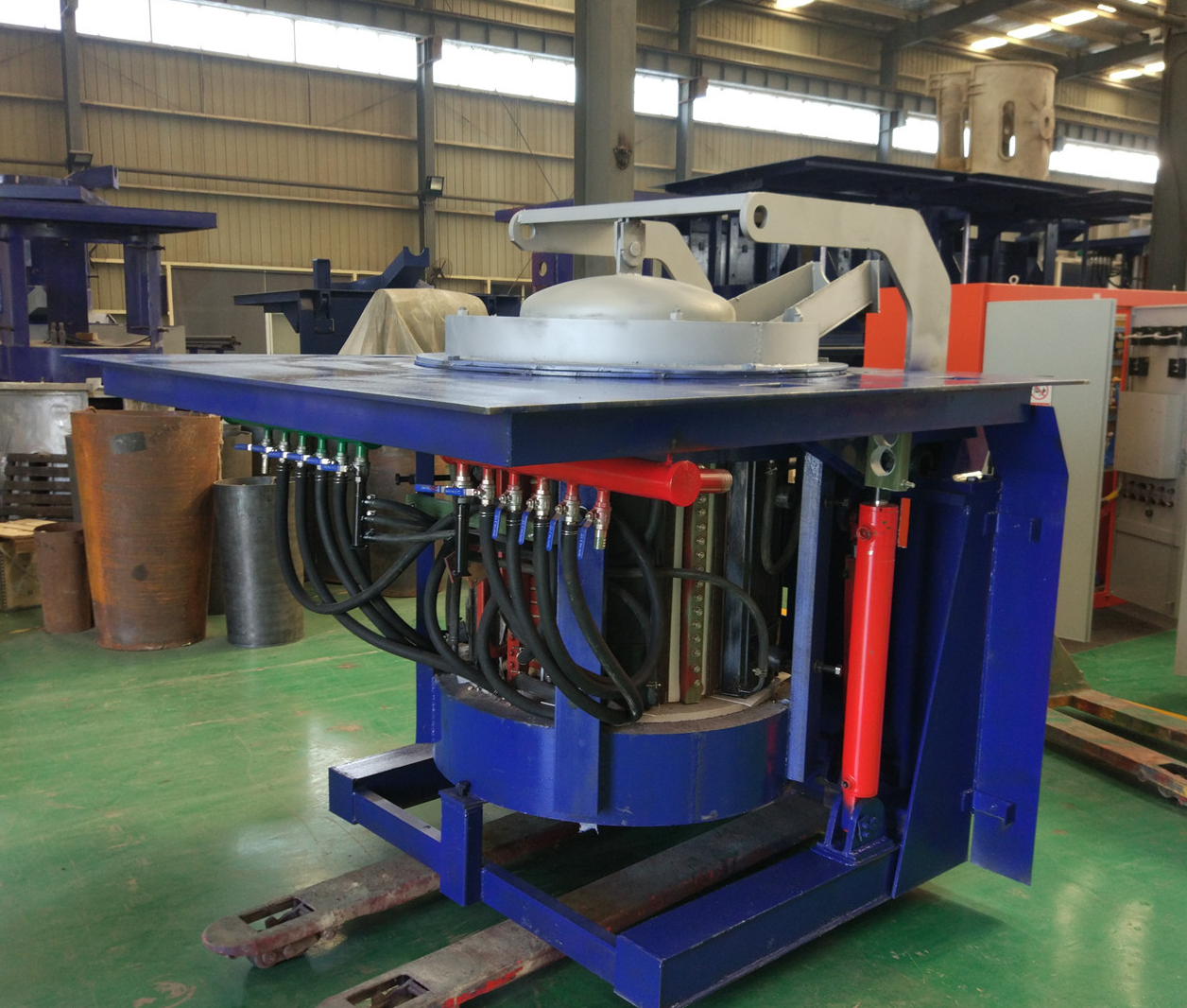
Iron induction furnace
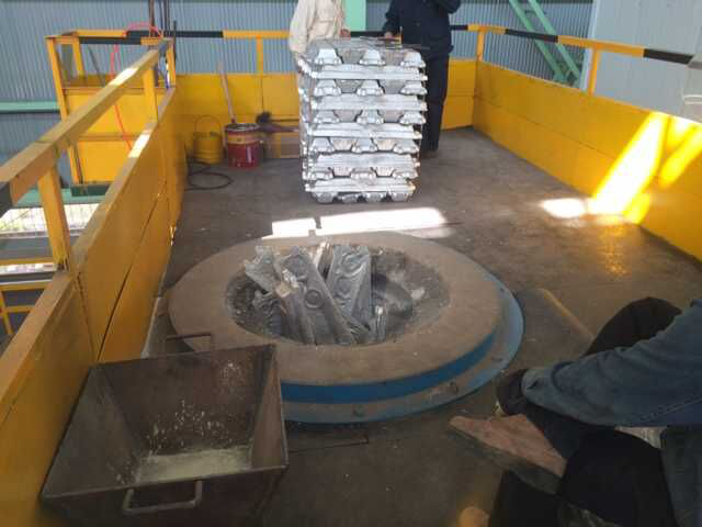
Aluminum melting furnace
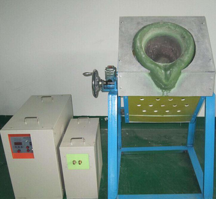
Copper melting furnace
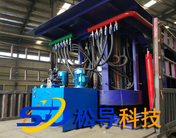
Small steel melting furnace
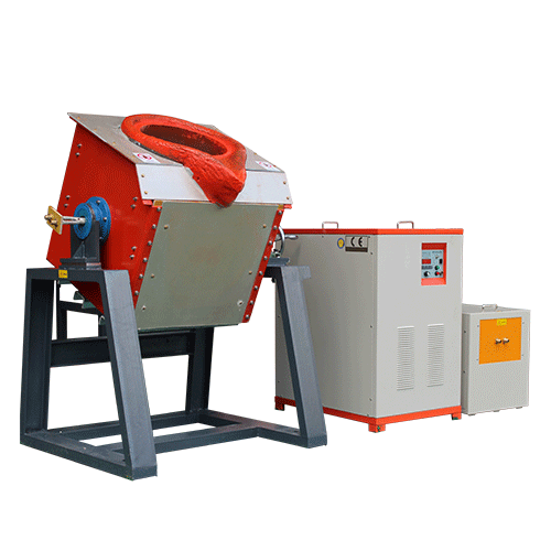
Small induction melting furnace
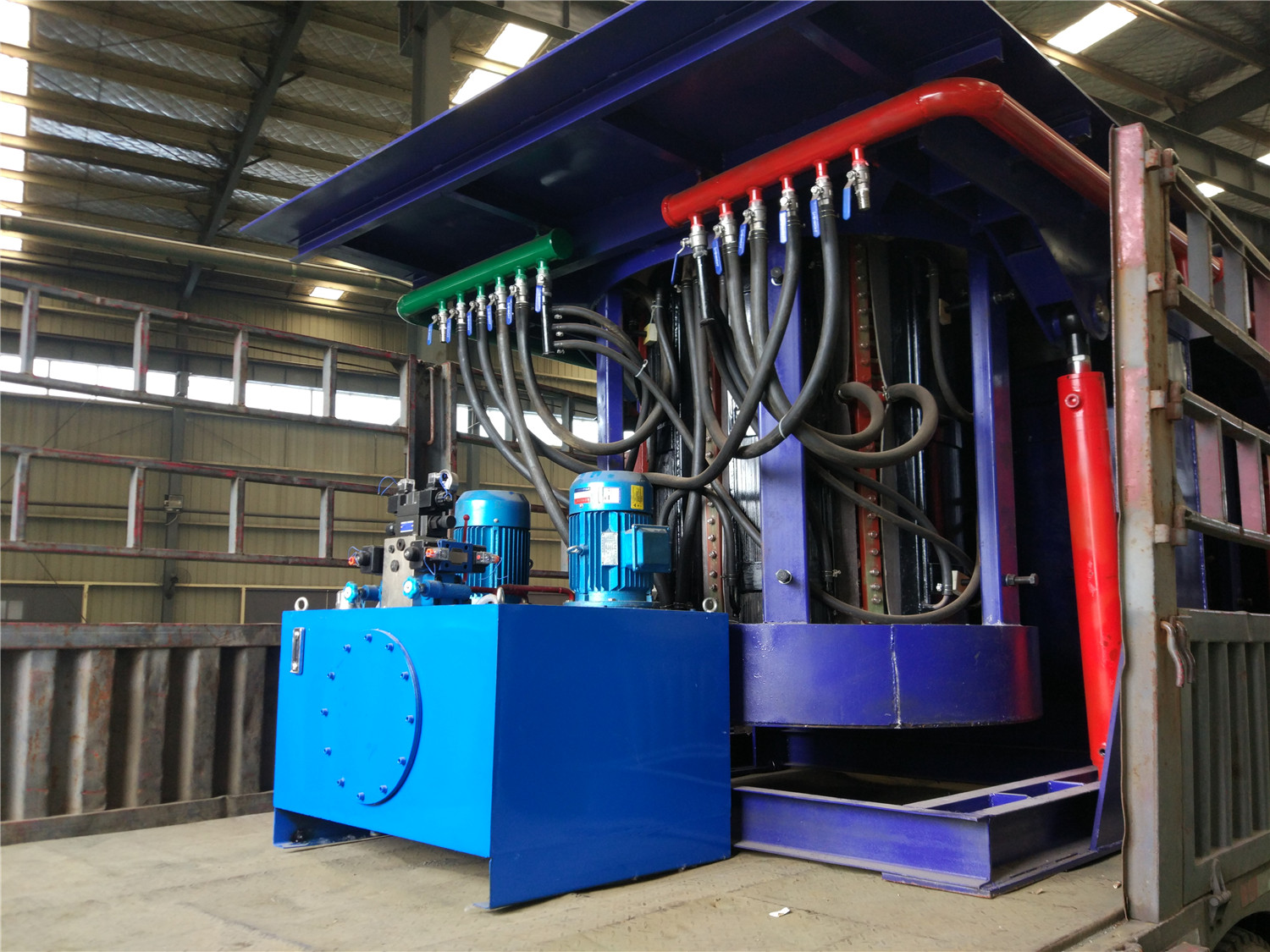
Induction iron furnace
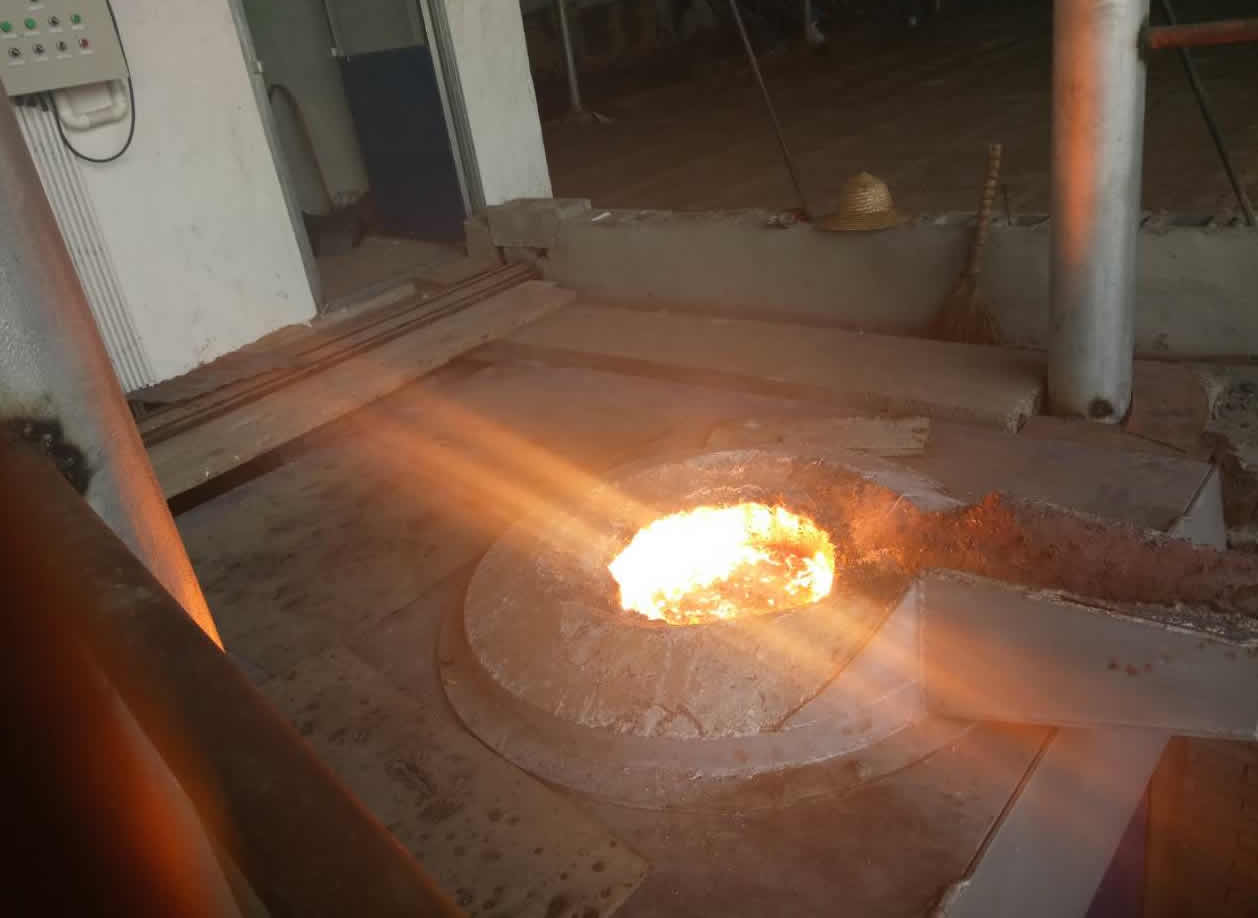
3T intermediate frequency iron melting f
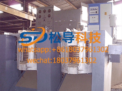
0.25T Intermediate Frequency Furnace
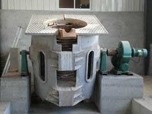
0.5T Intermediate Frequency Furnace
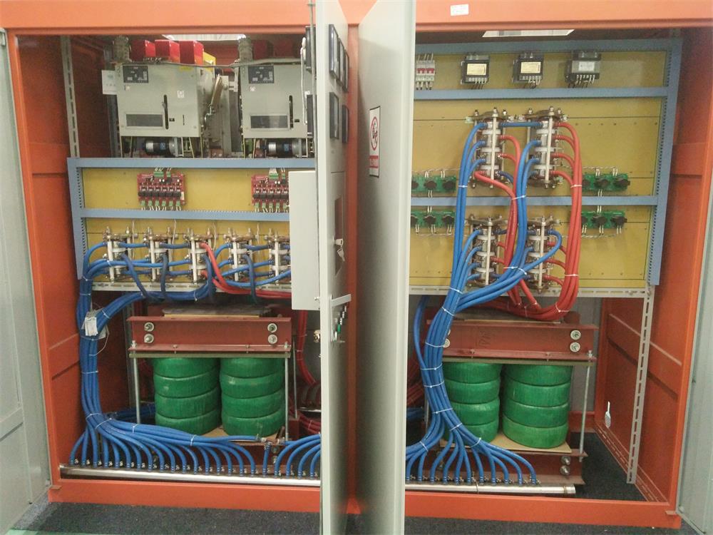
Medium Frequency Furnace

2T Induction Melting Furnace
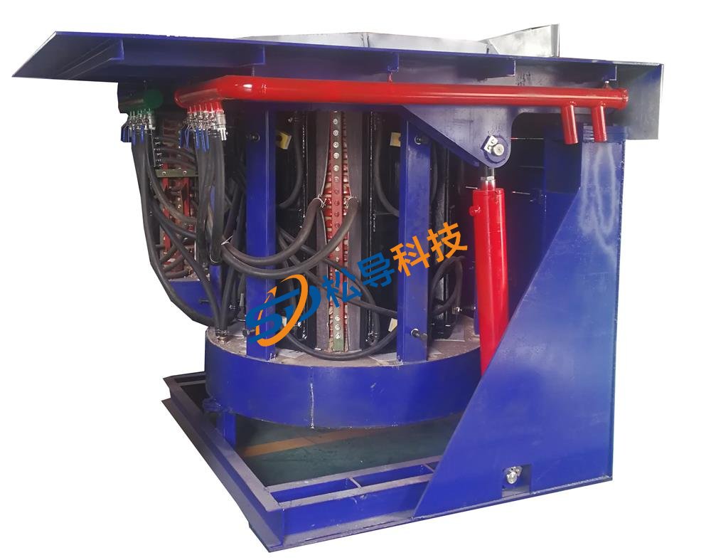
1T Induction Melting Furnace
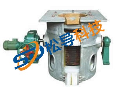
500kg Induction Melting Furnace
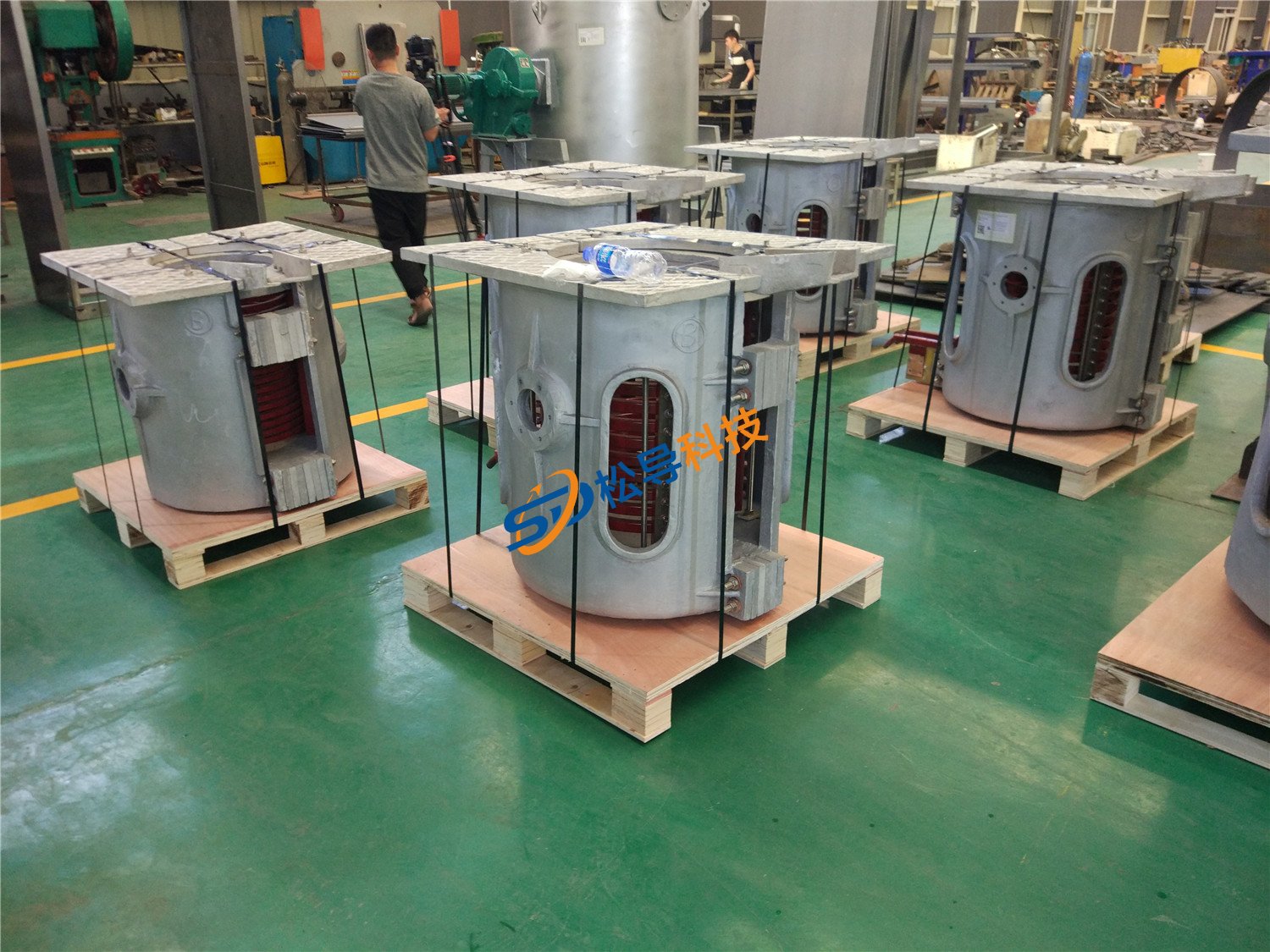
250kg Induction Melting Furnace
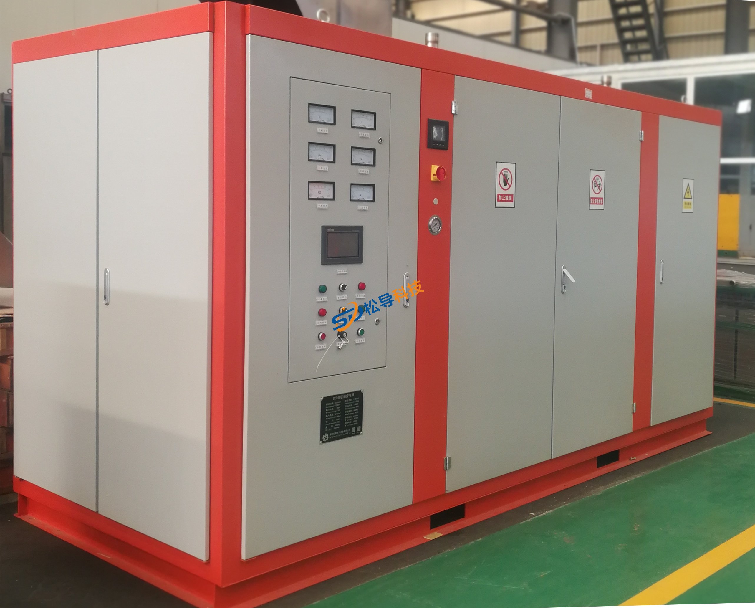
Induction Melting Furnace
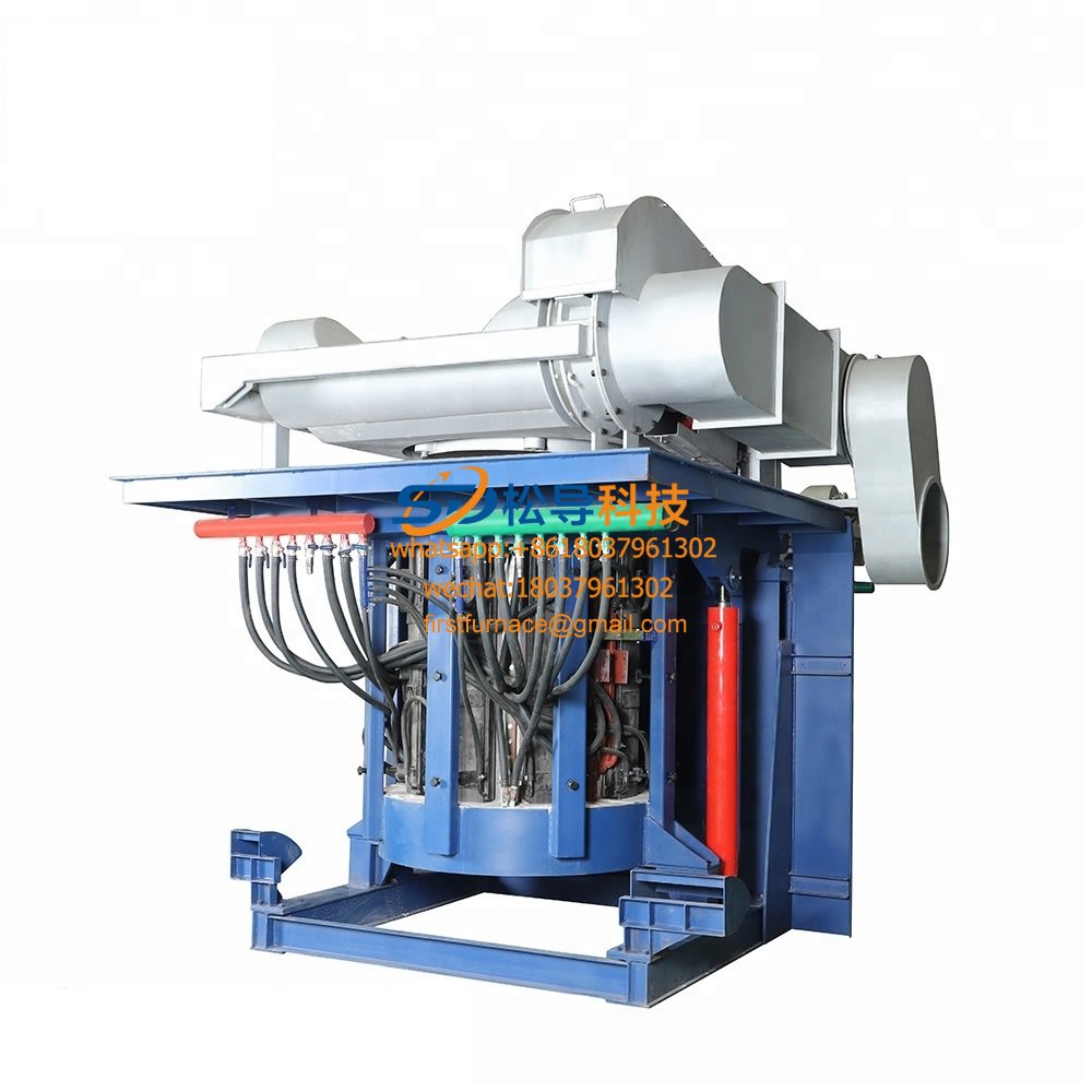
3 T Induction Melting Furnace
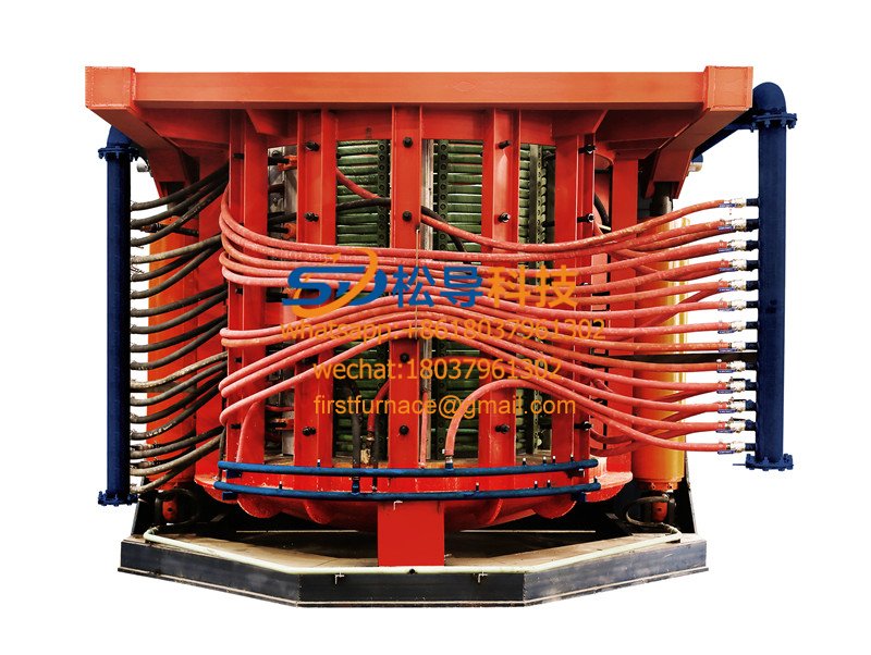
5T Induction Melting Furnace

1T One Belt Two Intermediate Frequency F

5T One Belt Two Intermediate Frequency F
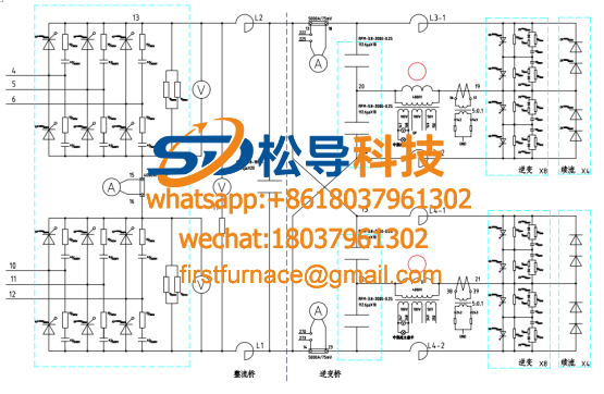
3T One Belt Two Intermediate Frequency F

2T One Belt Two Intermediate Frequency F
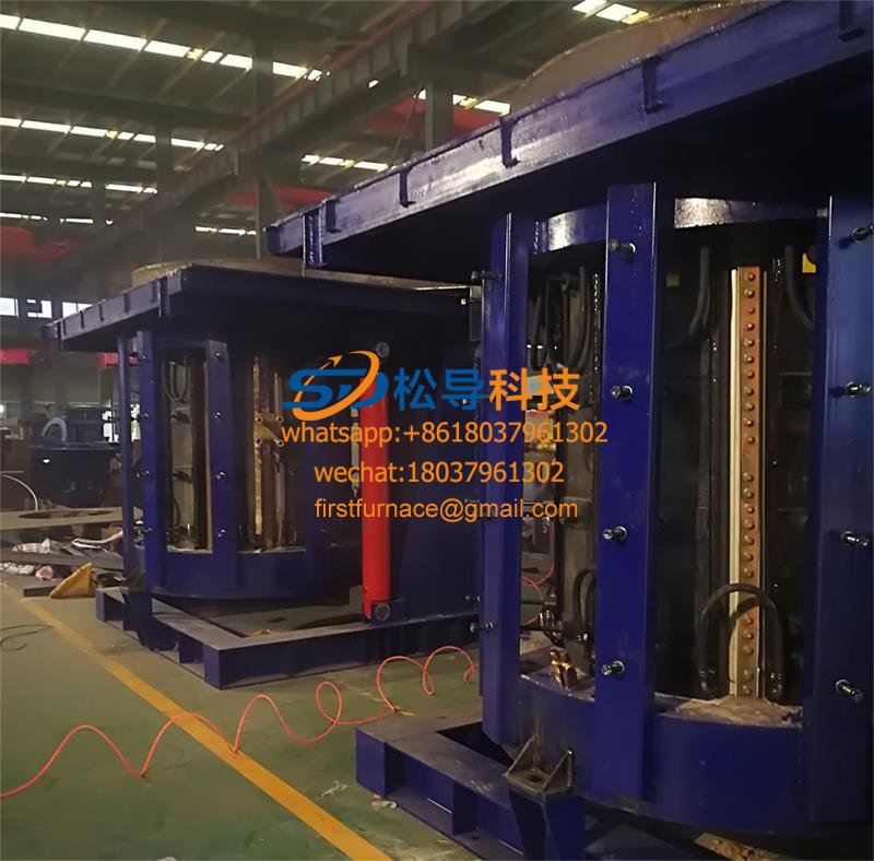
5T Parallel Intermediate Frequency Furna
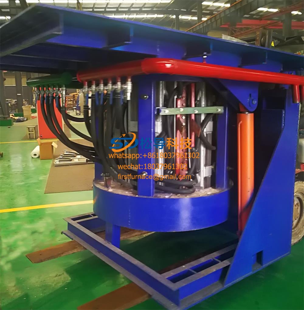
5T Intermediate Frequency Furnace

5T Series Intermediate Frequency Furnace
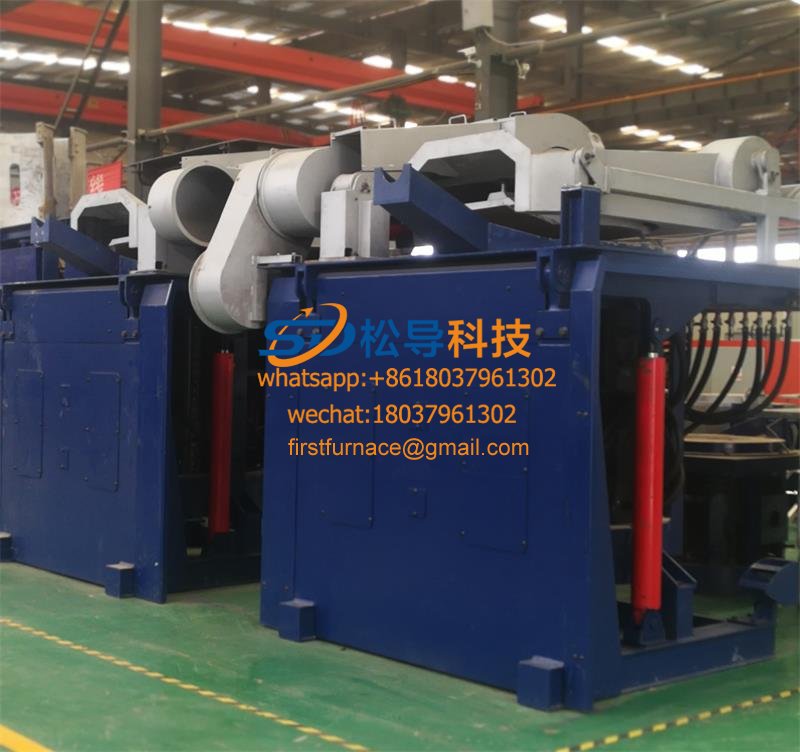
3T Series Intermediate Frequency Furnace
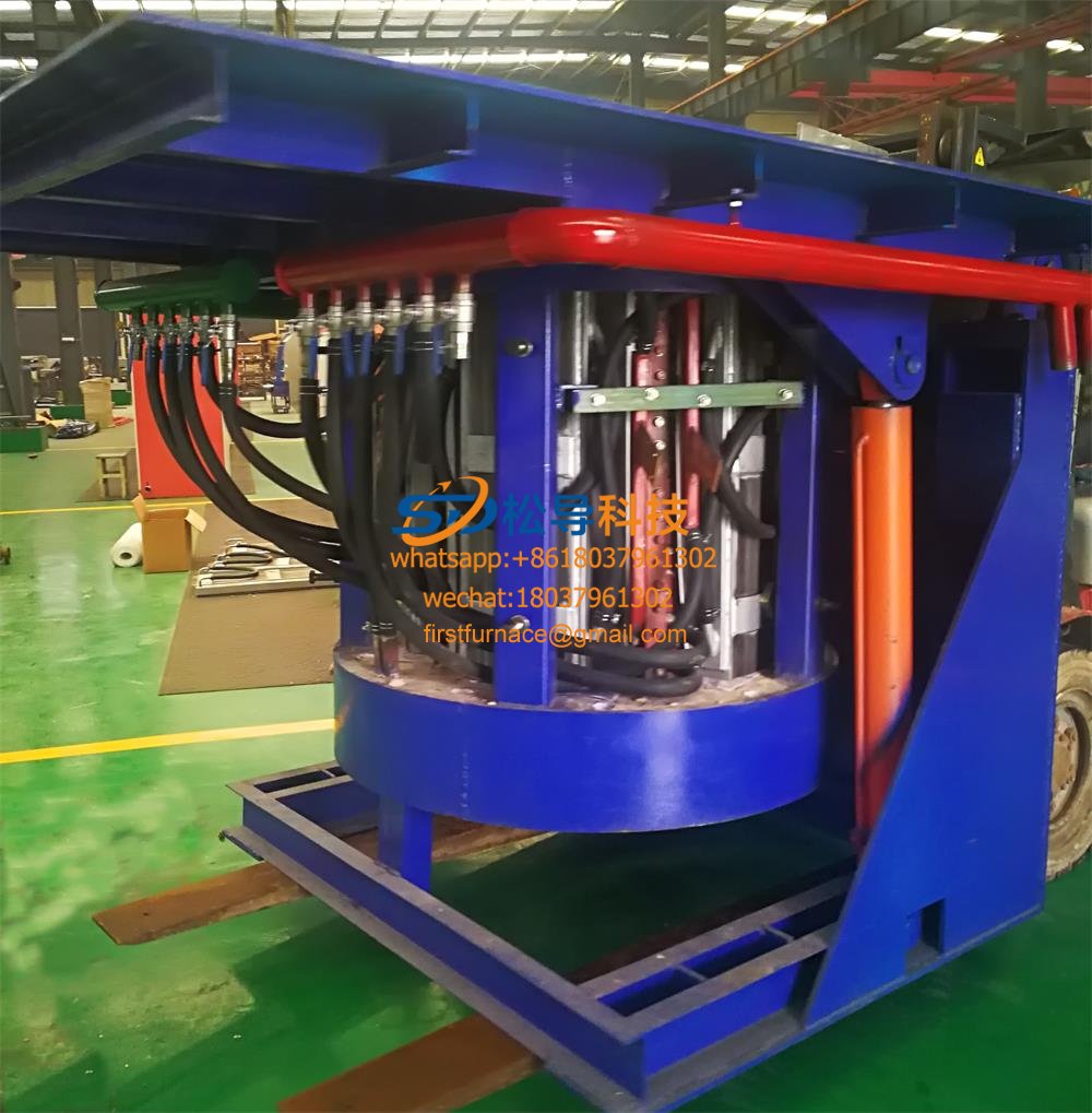
2T Series Intermediate Frequency Furnace
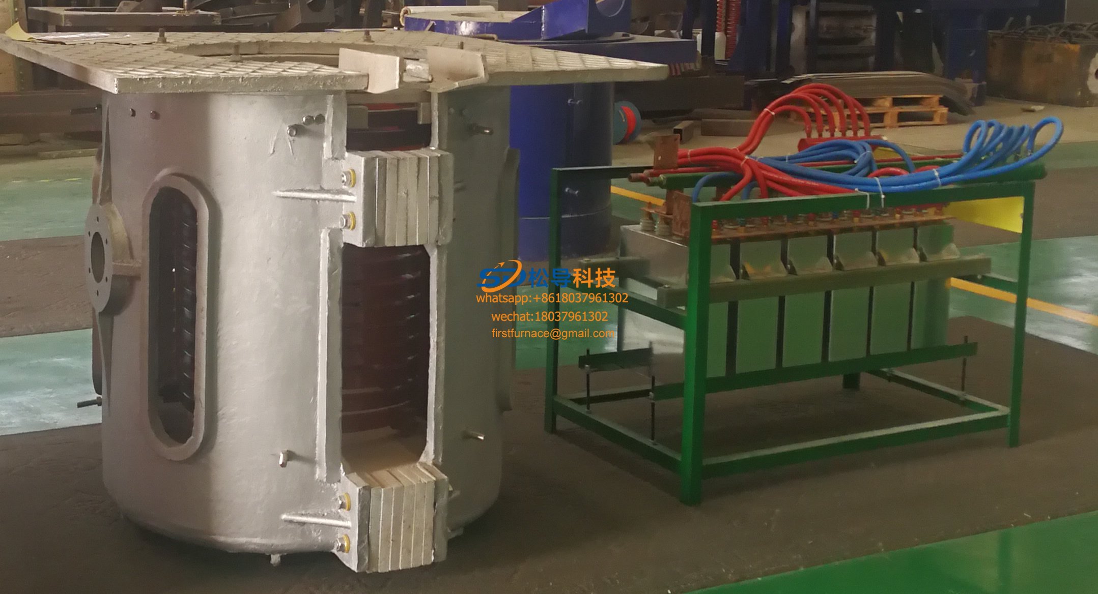
1T Series Intermediate Frequency Furnace
0.5T Series Intermediate Frequency Furna

0.25T Series Intermediate Frequency Furn
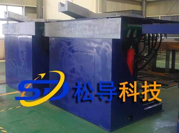
1T Parallel Intermediate Frequency Furna
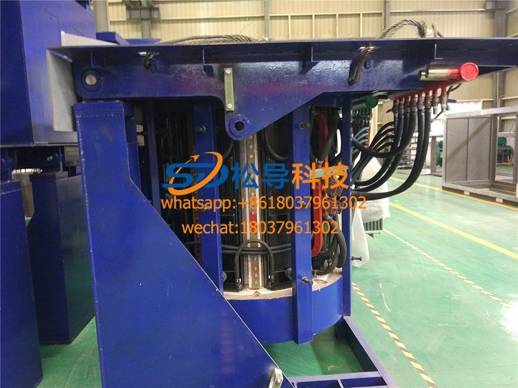
2T Parallel Intermediate Frequency Furna
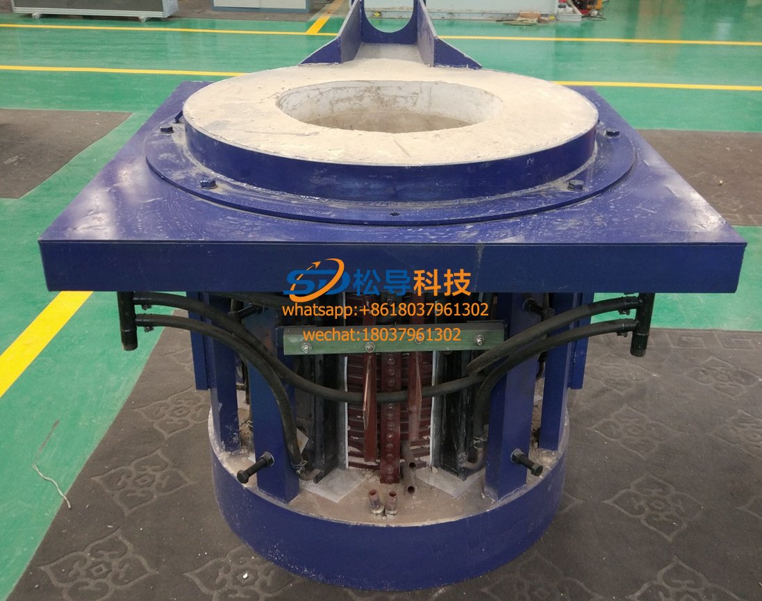
0.5T Parallel Intermediate Frequency Fur


