Sales hot line ( 24 hours service): 18037961302
E-Mail: firstfurnace@gmail.com
whatsapp:+8618037961302
Adress: Luoxin Industrial Park, Luoyang, HenanLarge diameter steel pipe quen
Piston rod quenching and tempe
Grinding rod quenching and tem
High frequency induction heate
Quenching equipment for machin
Round steel end heating furnac
Steel pipe heat treatment prod
Square steel quenching and tem
Sucker rod quenching and tempe
Thickened petroleum steel pipe
Round steel quenching and temp
Steel pipe quenching and tempe
Steel plate quenching and temp
Induction Hardening Machine&nb
Flywheel ring gear high freque
Utility model inductor and induction melting furnace.
At present, inductors in induction melting furnaces are mostly wound by spiral winding, that is, rectangular copper pipes are wound along a spiral path, as shown in Figure 1. However, the wound sensor has the following problems:
1. The efficiency of converting electric field energy into effective magnetic field energy is very low. Because it is a spiral path, the path of the copper tube forms an angle a with the horizontal plane, and the magnetic field lines generated by it are not completely perpendicular. Most of the magnetic field lines will act on the object to be heated, and a small part will act on the adjacent rectangular copper tube. So that this part of the magnetic field energy acting on the adjacent rectangular copper tube is lost;
2. The head end and the end of the spiral winding will occupy a single circle position, that is, a part of the space is wasted (shown at b in Figure 1) and cannot be connected to the adjacent circle, and the rated tonnage of the inductor The height and the number of turns are determined. Because the position of one more turn is occupied separately, the height of the rectangular copper tube used for winding will decrease, the resistance value will increase, and the loss will increase;
3. This spiral winding method has the same structure as the spring, so it also exhibits the characteristics of extension and contraction during use, which increases the vibration and makes the insulating material between the copper pipes easy to fall off, resulting in insulation performance decline.
The utility model solves the above technical problems through the following technical solutions:
An inductor, which is characterized in that it comprises a multi-turn copper tube coil formed after being wound on a reel, and each turn of the copper tube
The coils all include a horizontal winding section and a bending section, and the plane of each horizontal winding section is perpendicular to the axis of the reel.
Straight, the horizontal winding sections of any two-turn copper tube coil are parallel to each other and have the same length, and the bending sections of any two-turn copper tube coil are in phase with each other.
Parallel to each other and the same length. Due to the existence of the bending section, each horizontal winding section can always be aligned with the axis of the reel.
Keep it vertical, so the electromagnetic conversion efficiency is high. And the start and end of the sensor will not occupy a circle separately, and the additional copper pipe
The average height of the coil can reduce the impedance of the inductor, reduce the energy loss of the inductor itself, and the inductor no longer has
The structure of the spring has low vibration and improves the insulation performance. The copper tube of the copper tube coil is a rectangular copper tube. The cross section is round or rectangular. There is an interval between two adjacent turns of copper tube coils, and the multi-turn copper tube coils are fixed on a bakelite column. Insulating material is provided in the compartment. It is characterized in that the induction melting furnace includes the inductor as described above. Each horizontal winding section can always be vertical to the axis of the reel, so that the electromagnetic conversion efficiency is high, and the start and end of the inductor will not occupy a single circle. The average height of the increased copper tube coil can reduce the inductor Impedance, thereby reducing the energy loss of the inductor itself, and the inductor no longer has a spring structure, with low vibration and improved insulation performance.
Description of the drawings
FIG. 1 is a schematic diagram of the structure of a conventional sensor.
FIG. 2 is a schematic diagram of the structure of an inductor according to an embodiment of the present invention.
Fig. 3 is a schematic structural diagram of an apparatus for manufacturing an inductor according to an embodiment of the present invention.
http://www.songdaokeji.com/plus/list.php?tid=49
http://www.songdaokeji.com/plus/list.php?tid=22
http://www.songdaokeji.com
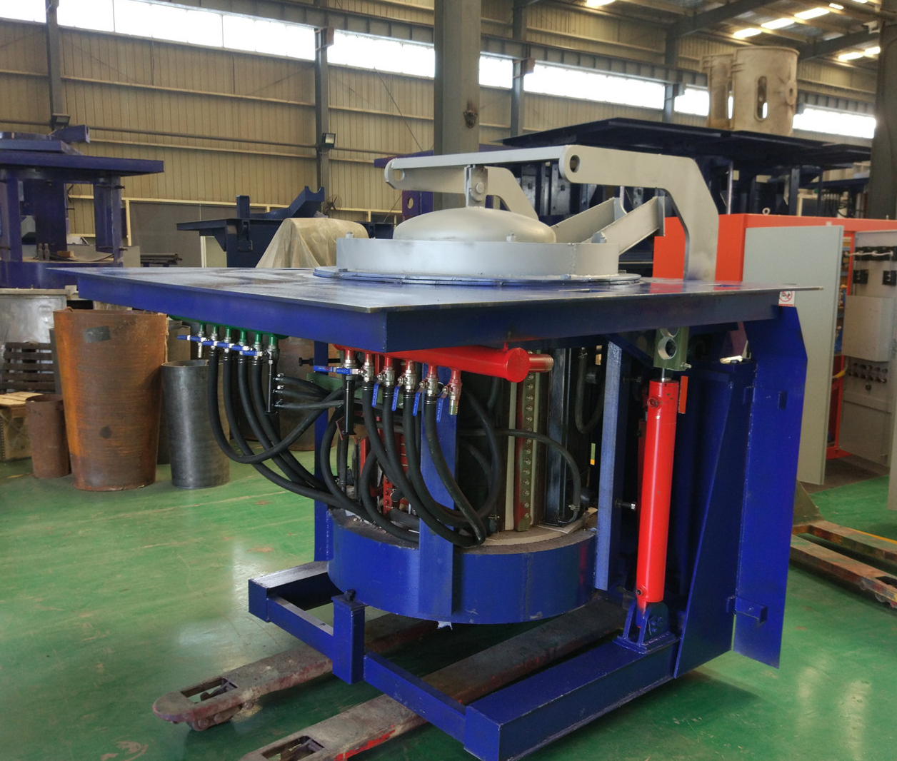
Iron induction furnace
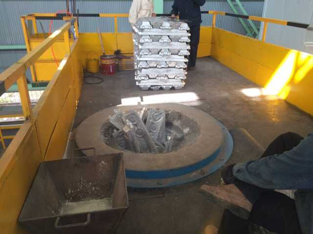
Aluminum melting furnace
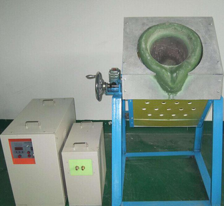
Copper melting furnace
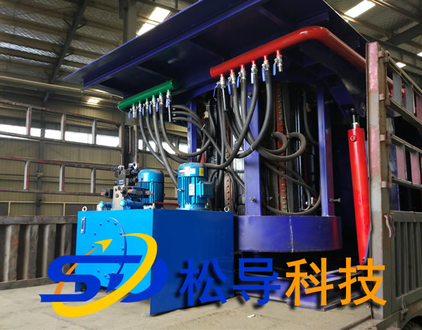
Small steel melting furnace
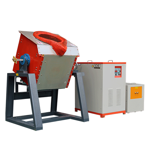
Small induction melting furnace
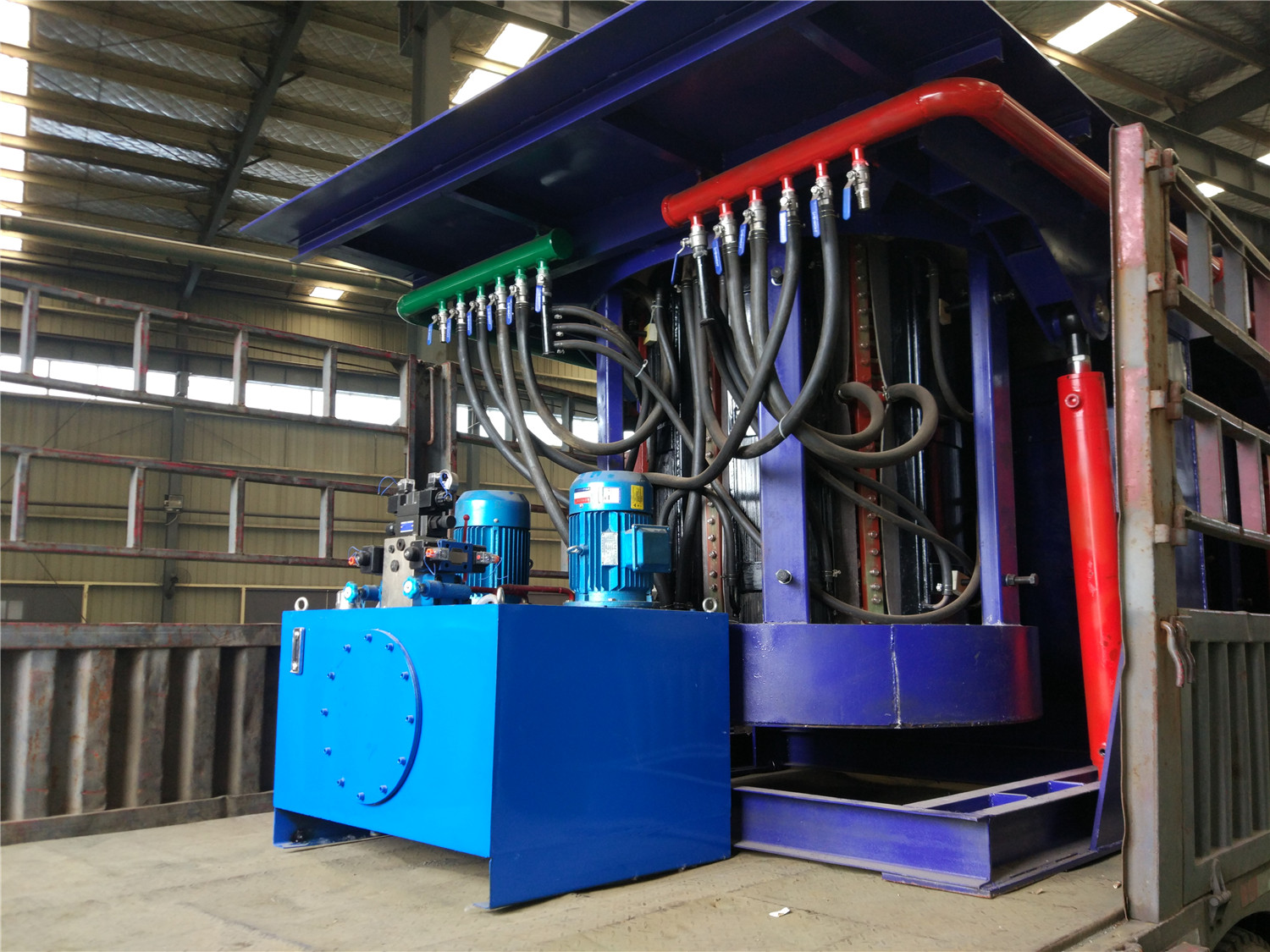
Induction iron furnace
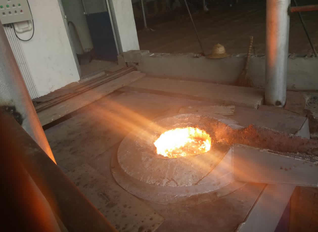
3T intermediate frequency iron melting f
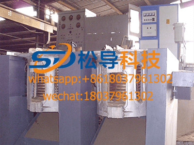
0.25T Intermediate Frequency Furnace
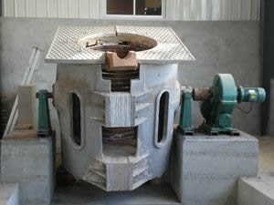
0.5T Intermediate Frequency Furnace
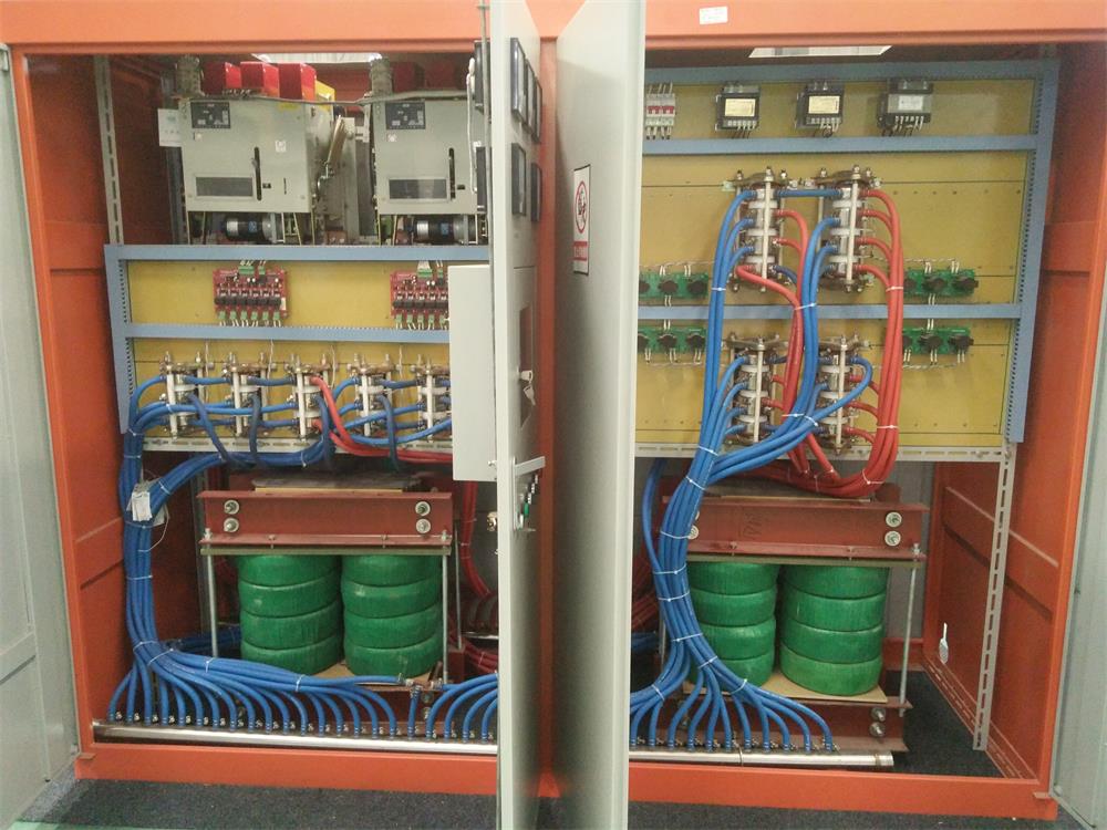
Medium Frequency Furnace

2T Induction Melting Furnace
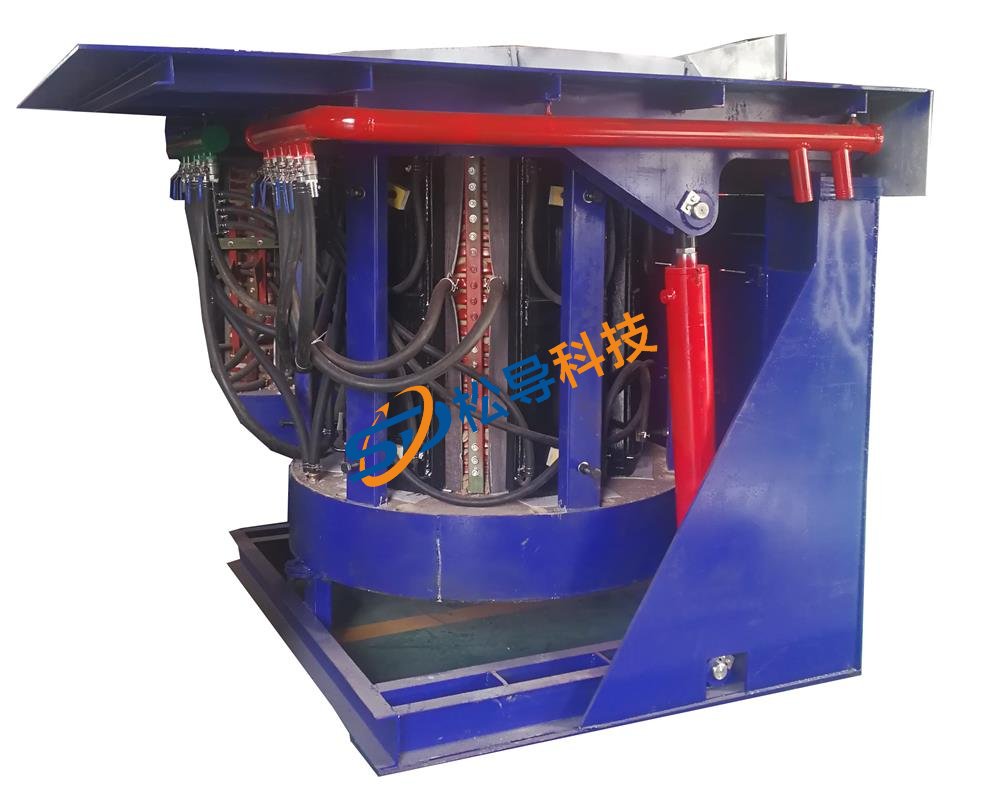
1T Induction Melting Furnace
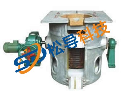
500kg Induction Melting Furnace
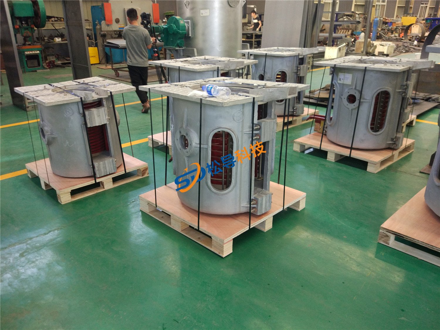
250kg Induction Melting Furnace
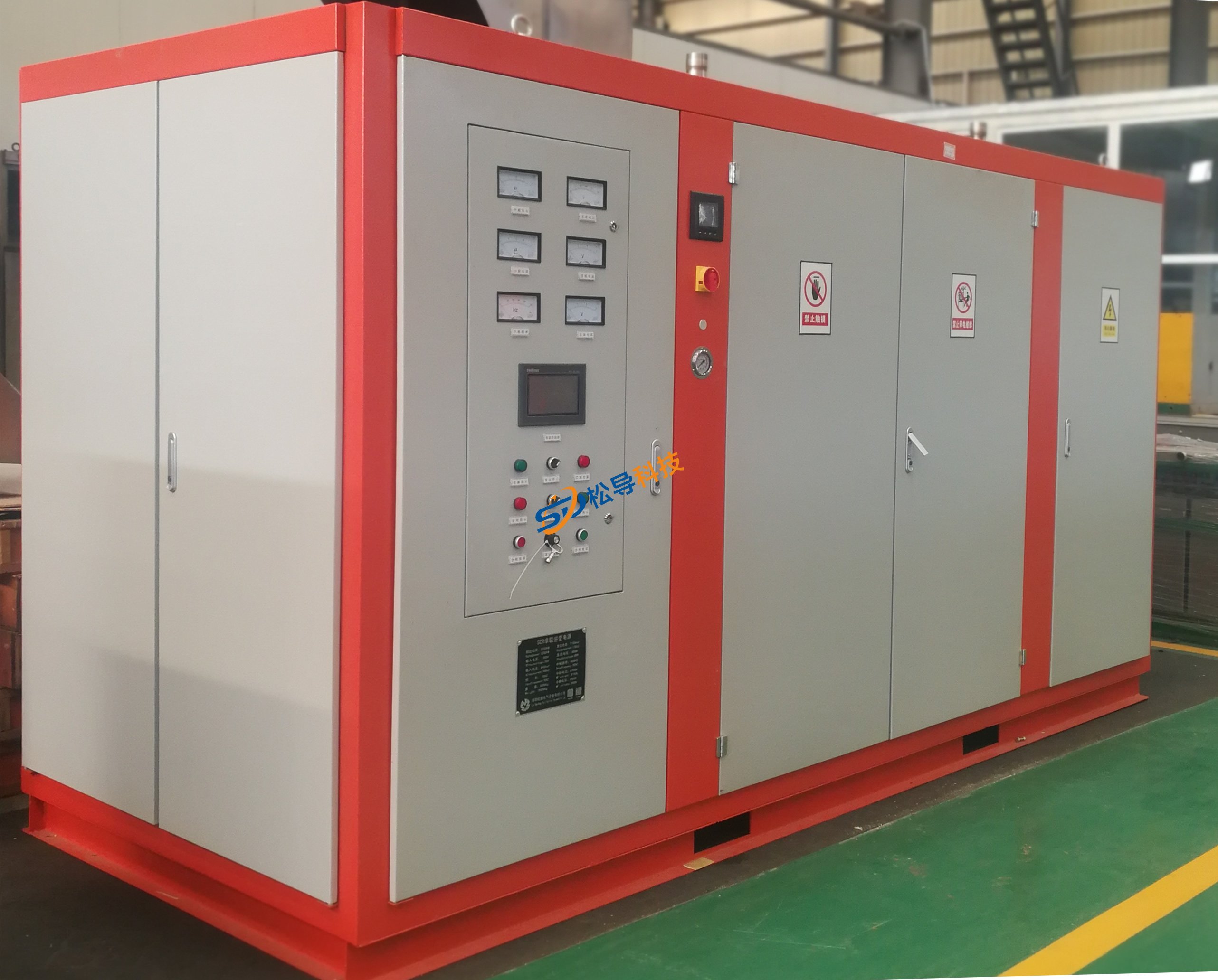
Induction Melting Furnace
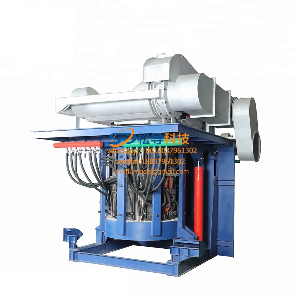
3 T Induction Melting Furnace
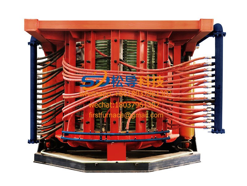
5T Induction Melting Furnace
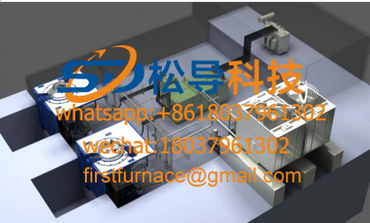
1T One Belt Two Intermediate Frequency F

5T One Belt Two Intermediate Frequency F
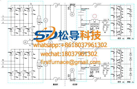
3T One Belt Two Intermediate Frequency F
2T One Belt Two Intermediate Frequency F
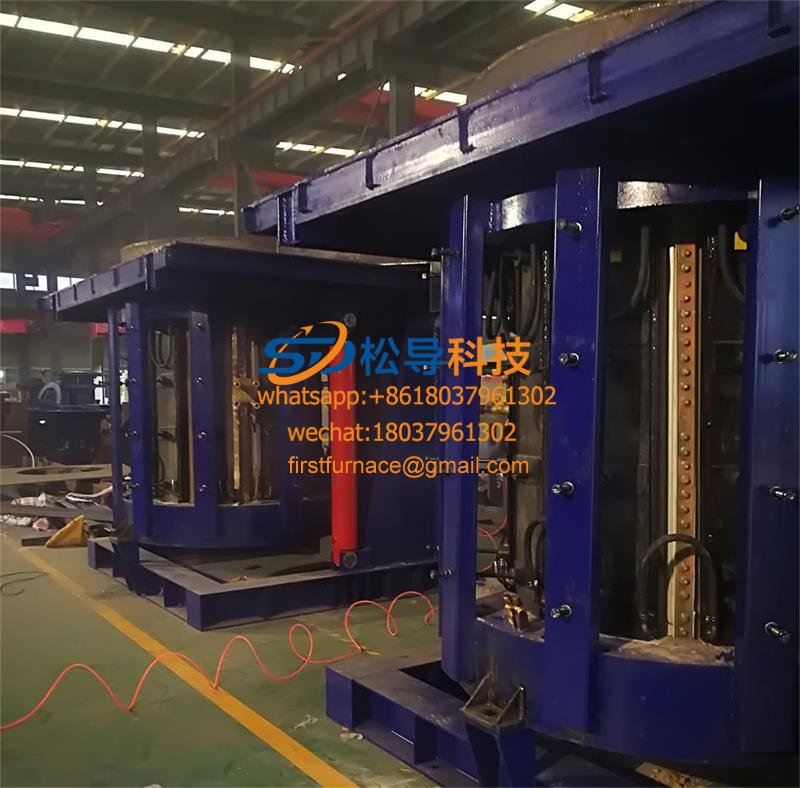
5T Parallel Intermediate Frequency Furna
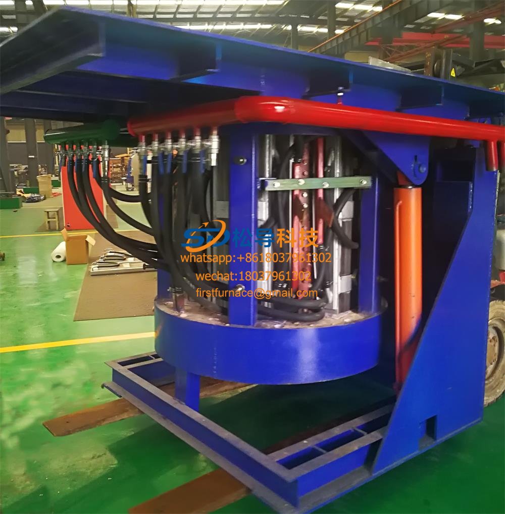
5T Intermediate Frequency Furnace

5T Series Intermediate Frequency Furnace
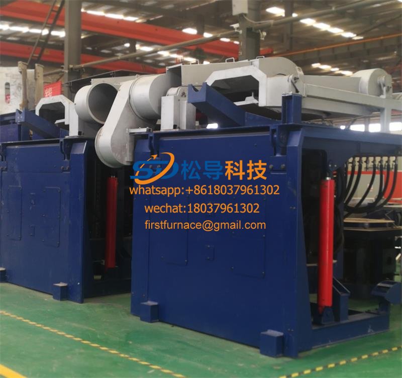
3T Series Intermediate Frequency Furnace
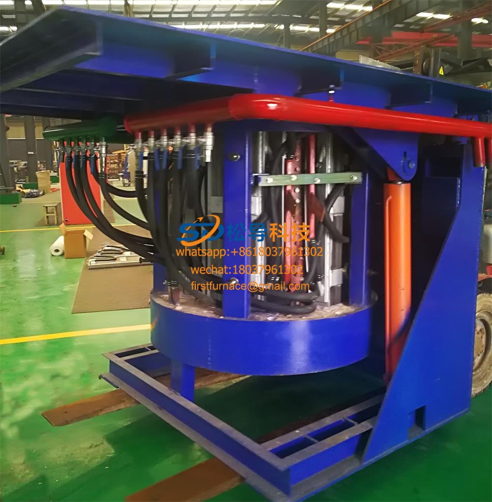
2T Series Intermediate Frequency Furnace
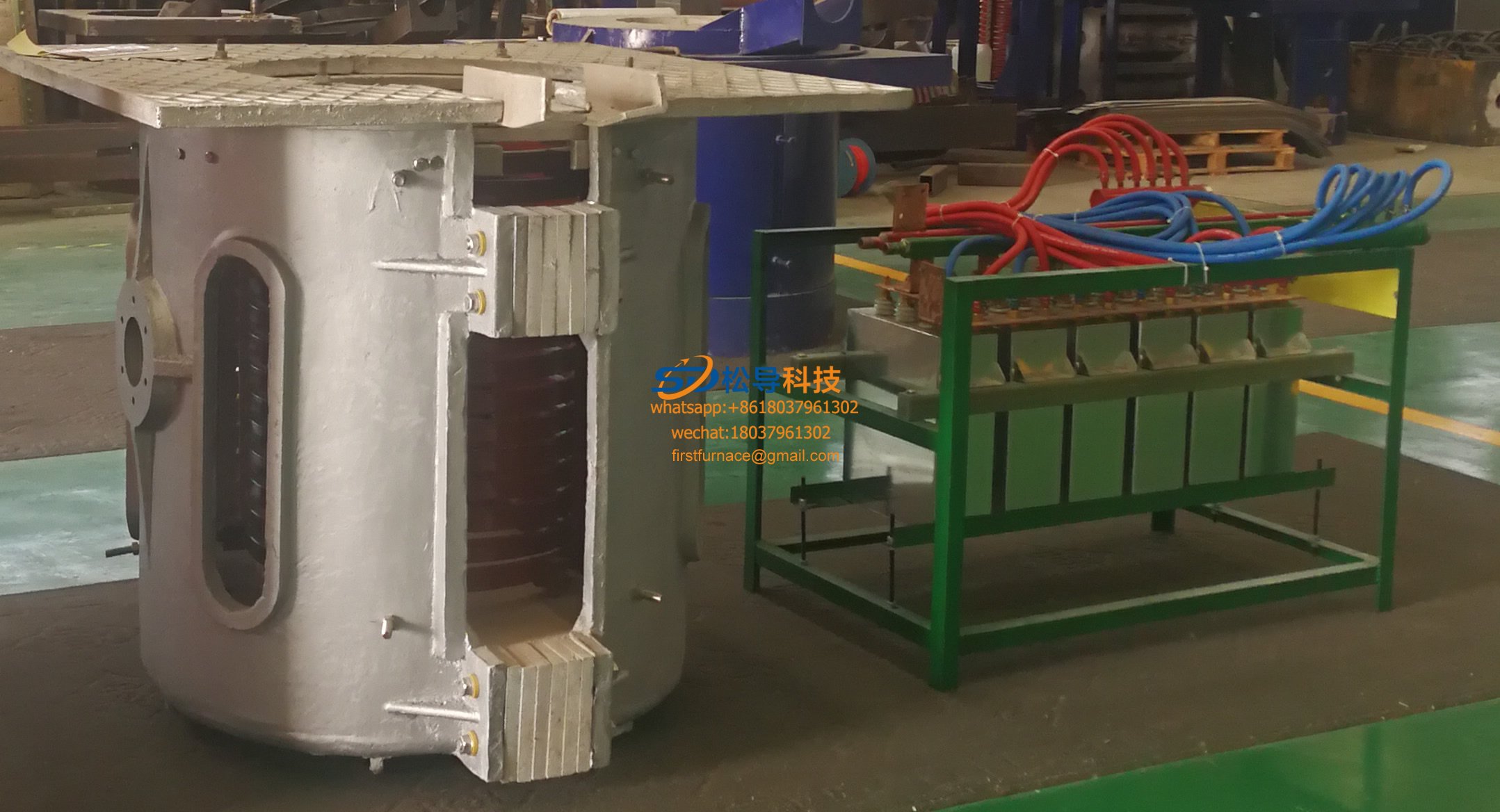
1T Series Intermediate Frequency Furnace
0.5T Series Intermediate Frequency Furna

0.25T Series Intermediate Frequency Furn
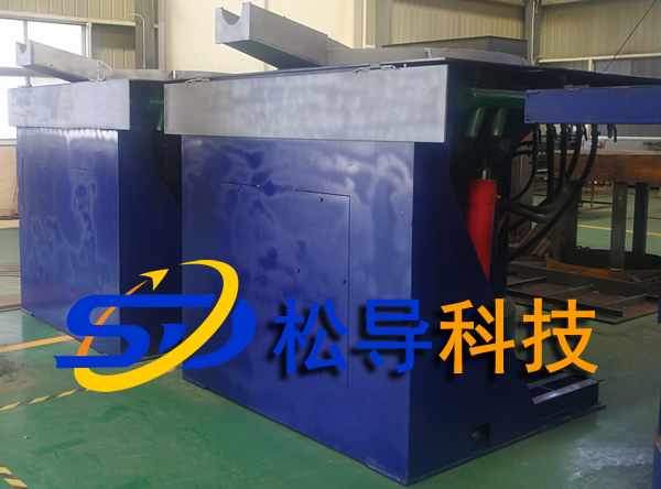
1T Parallel Intermediate Frequency Furna
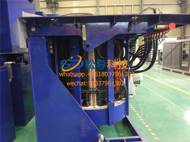
2T Parallel Intermediate Frequency Furna
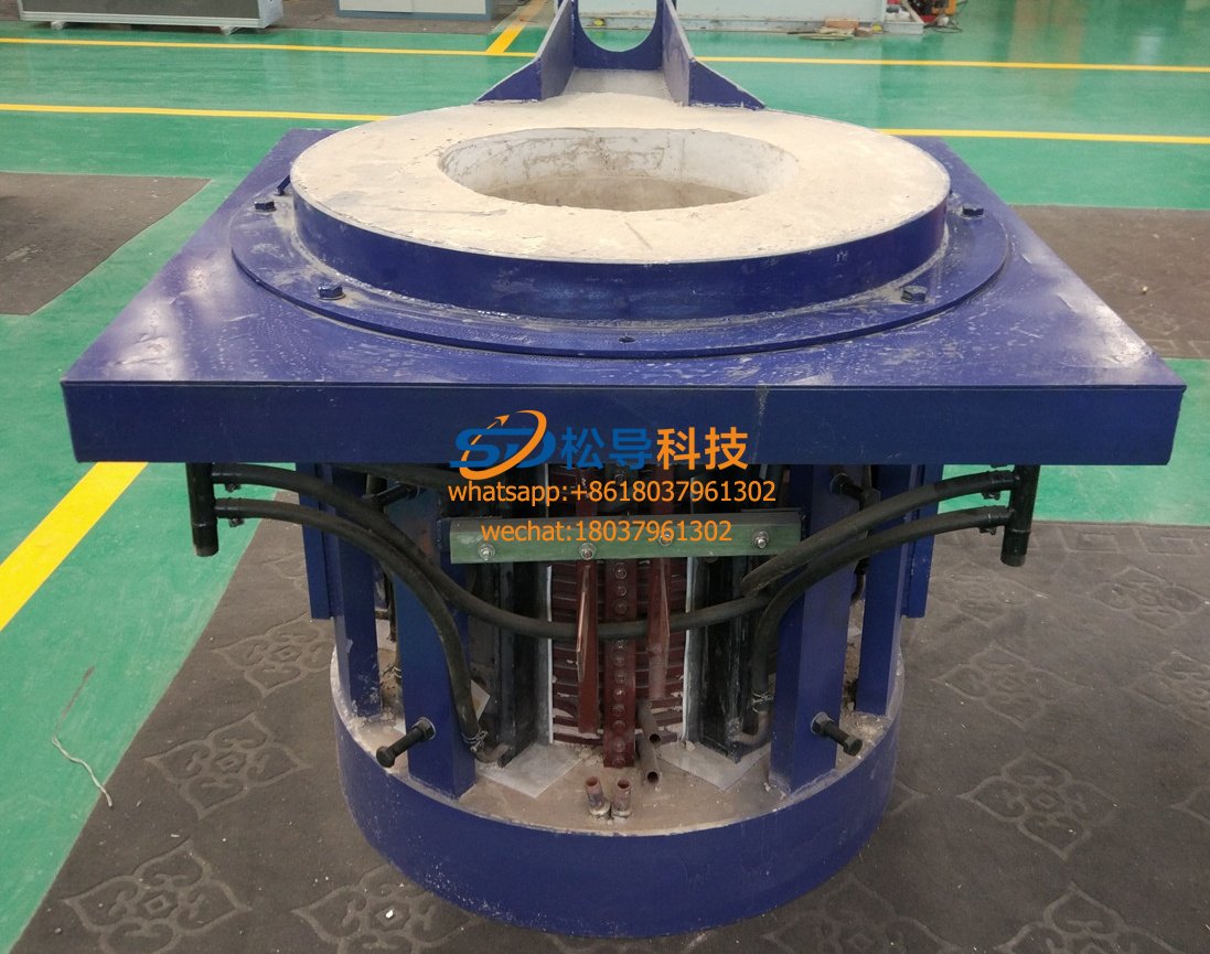
0.5T Parallel Intermediate Frequency Fur


