Sales hot line ( 24 hours service):+86 13015583380
E-Mail: firstfurnace@gmail.com
whatsapp:+86 13015583380
Adress: Luoxin Industrial Park, Luoyang, HenanLarge diameter steel pipe quen
Piston rod quenching and tempe
Grinding rod quenching and tem
High frequency induction heate
Quenching equipment for machin
Round steel end heating furnac
Steel pipe heat treatment prod
Square steel quenching and tem
Sucker rod quenching and tempe
Thickened petroleum steel pipe
Round steel quenching and temp
Steel pipe quenching and tempe
Steel plate quenching and temp
Induction Hardening Machine&nb
Flywheel ring gear high freque
Special venting brick technology for refining induction melting furnace
Background technique
At present, high-grade alloy steel, stainless steel, ultra-low carbon steel, etc. are smelted in various induction melting furnaces. The purity and alloy composition of molten steel are difficult to meet the technical requirements. The key is argon blowing in the furnace for refining. However, in the induction melting furnace, due to the electrical conductivity of the metal shell structure, the ventilating bricks in the bottom of the furnace are electrically induced, the metal shell is oxidized and red, and the oxidized iron sheet falls off, causing the metal shell to open welding, which makes it difficult to weld. Ensure the technical requirements of the steel type.
The purpose of the utility model is to provide a ventilated brick for induction melting furnace, which is a sealed air chamber formed by the ceramic end cover and the groove at the bottom of the ventilated brick core, and the ventilated brick in the bottom of the furnace will not be subjected to electric induction. , Use the argon gas pressed into the gas chamber to directly blow argon to the induction melting furnace for refining. The following structure is adopted to achieve: a protective layer of air-permeable bricks, and a conical hole with an opening at the top is opened in the conical hole, and a matching truncated-cone air-permeable brick core is provided in the conical hole, and the core of the air-permeable brick A groove is provided at the bottom of the groove, and a sealed ceramic end cover is arranged under the groove, and a gas pipe extending out of the protective layer of the ventilating brick is pierced in the central hole in the center of the ceramic end cover. The lower end of the groove of the core is provided with an internal thread, and the ceramic end cap is a cylindrical flat plate, and an external thread that matches the internal thread of the groove of the ventilating brick core is provided on the cylindrical outer edge. The ceramic end cover is a concave disc, and the inner side of the outer edge is provided with an inner conical surface matched with the concave conical surface of the ventilating brick core. The ceramic end cover is a cylindrical flat plate, and its top plane abuts against the bottom surface of the groove of the ventilating brick core and is bonded with glue. The air chamber has reliable sealing performance and can avoid the influence of the inductance on the argon blowing in the furnace.
Description of the drawings
Fig. 1 is a cross-sectional view of the first embodiment of the present invention.
Figure 2 is a cross-sectional view of the second embodiment of the present utility model.
Figure 3 is a cross-sectional view of the third embodiment of the present utility model.
In the picture: 1. Breathable brick core, 1 1, groove, 1 2, internal thread, 1 3. outer cone surface,
14, concave cone surface, 2, ceramic end cap, 21, center hole, 22, external thread, 23, inner cone
Surface, 3. Protective layer of air-permeable bricks, 31, tapered hole, 32, central through hole, 33, fixing parts, 4.
Gas pipe.
Specific implementation of special ventilation brick for refining induction melting furnace
The first embodiment is composed of a ventilating brick core 1, a ceramic end cover 2, a ventilating brick protective layer 3, and a gas pipe 4, as shown in Figure 1, where the ventilating brick core 1 is truncated cone shape, and its bottom A groove 11 is provided. The lower part of the inner wall of the groove 11 of the ventilating brick core 1 is provided with an internal thread 12. The ventilating brick core 1 is made of refractory materials such as chromium corundum, and is provided with a narrow surface on the outer conical surface 13 Slotted long hole;
The ceramic end cover 2 is a cylindrical flat plate, and on the outer edge of the cylindrical shape is provided with an external thread 22 that matches the internal thread 12 of the inner wall of the groove 11 of the ventilating brick core 1 to prevent the groove of the ventilating brick core 1 The air chamber formed by 11 and the ceramic end cover 2 leaks air, and a central hole 21 is opened at the center of the ceramic end cover 2. The ceramic end cover 2 is a non-metallic object with high temperature resistance and high pressure resistance.
The air-permeable brick protective layer 3 is a truncated cone shape, and a conical hole 31 with an opening at the top is opened in it. A central through hole 32, one or two fixing members 33 are embedded at the edge of the central through hole 32, which belongs to the prior art;
The air pipe 4 penetrates the central hole 21 of the ceramic end cover 2 and the central through hole 32 of the air-permeable brick protective layer 3, and exposes the outside of the air-permeable brick protective layer 3. The air pipe 4 is a pipe made of ceramic or metal, and One or two fixing members 33 embedded in the air-permeable brick expansion layer 3 are fixed to make the ceramic end cover 2 and the air-permeable brick core 1 more securely combined, which belongs to the prior art.
The ceramic end cover 2 of the second embodiment is a concave disc, and the inner side of the upper edge is an inner conical surface 23 that matches the concave conical surface 14 of the ventilating brick core 1 to prevent the ventilating brick core 1 from being concave. The air chamber formed by the groove 11 and the ceramic end cover 2 leaks air, as shown in FIG. 2, and the rest of the structure is the same as that of the first embodiment, so it will not be repeated.
The ceramic end cover 2 of the third embodiment is a cylindrical flat plate, and its top plane abuts against the bottom surface of the groove 11 of the ventilating brick core 1, and adhesive bonding is added to prevent the groove 11 of the ventilating brick core 1 The air chamber formed with the ceramic end cover 2 leaks air, as shown in Figure 3, and the rest of the structure is the same as the first embodiment, so it will not be repeated
http://www.songdaokeji.com/plus/list.php?tid=49
http://www.songdaokeji.com/plus/list.php?tid=22
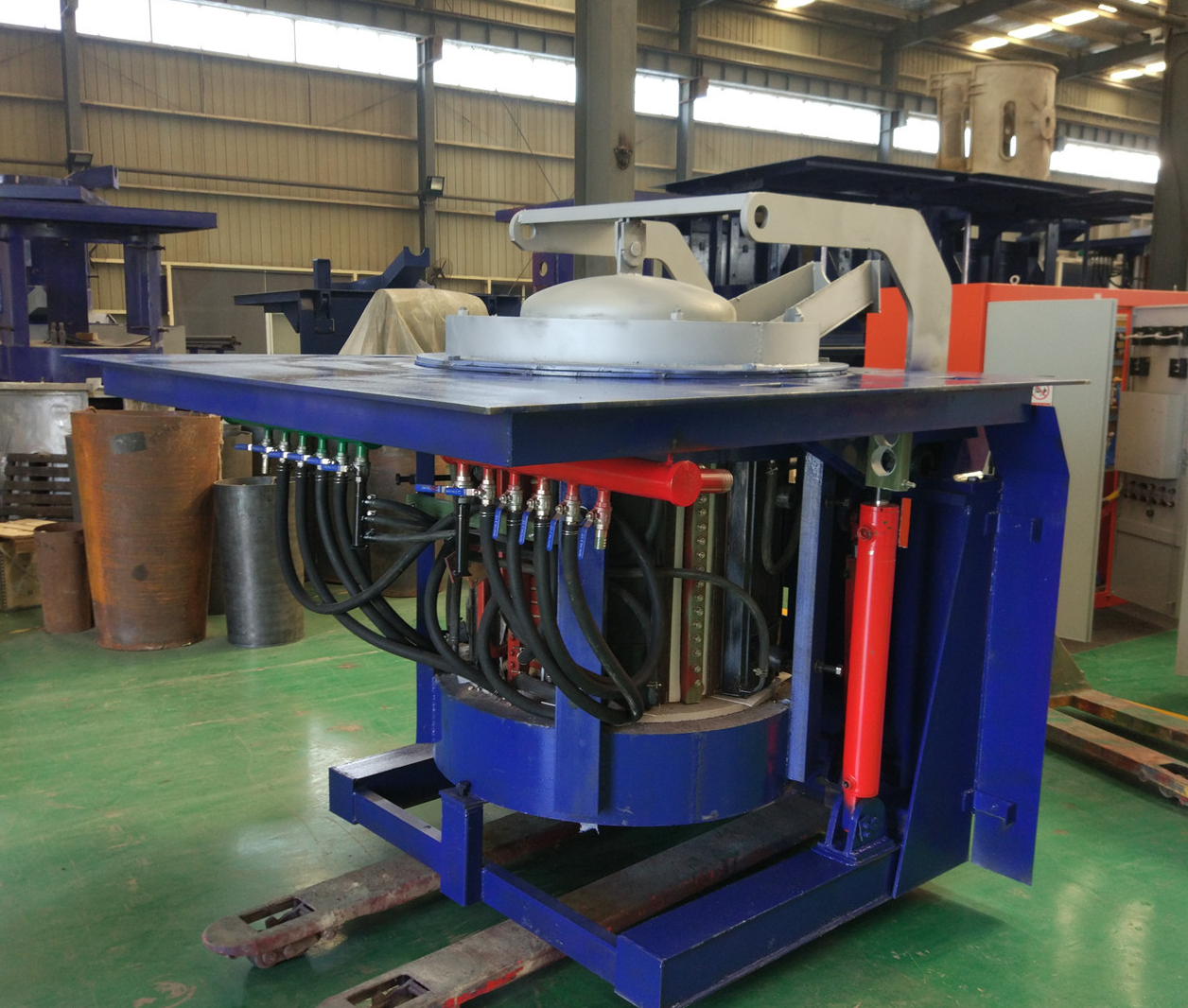
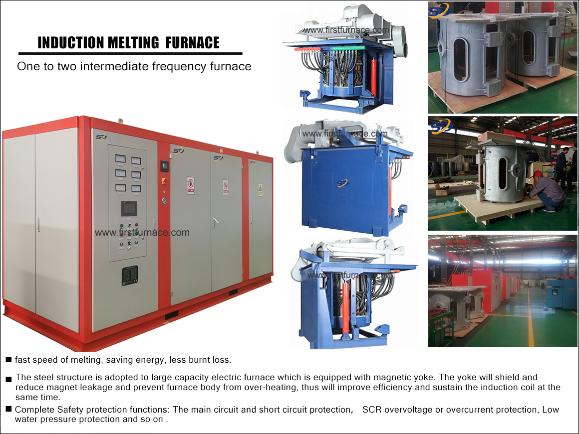
Iron induction furnace
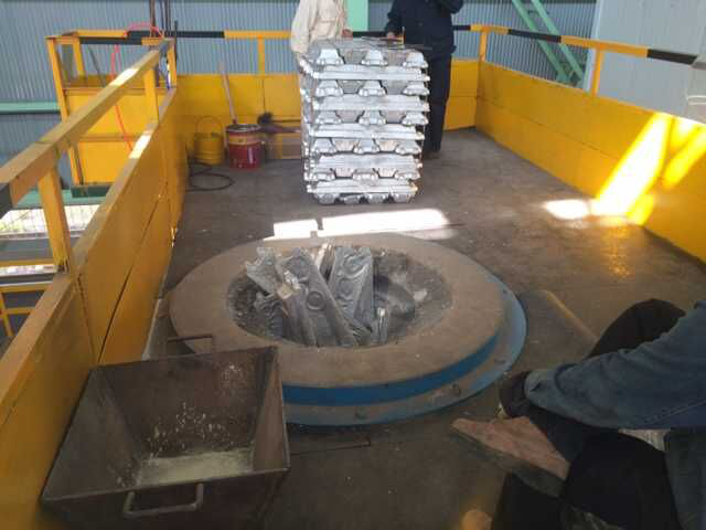
Aluminum melting furnace
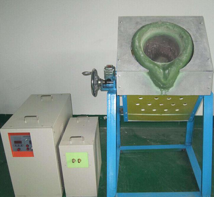
Copper melting furnace
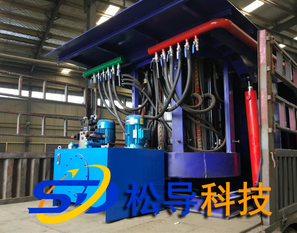
Small steel melting furnace
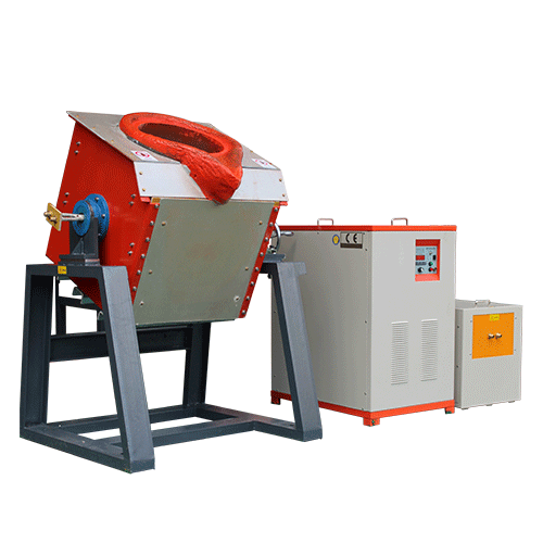
Small induction melting furnace
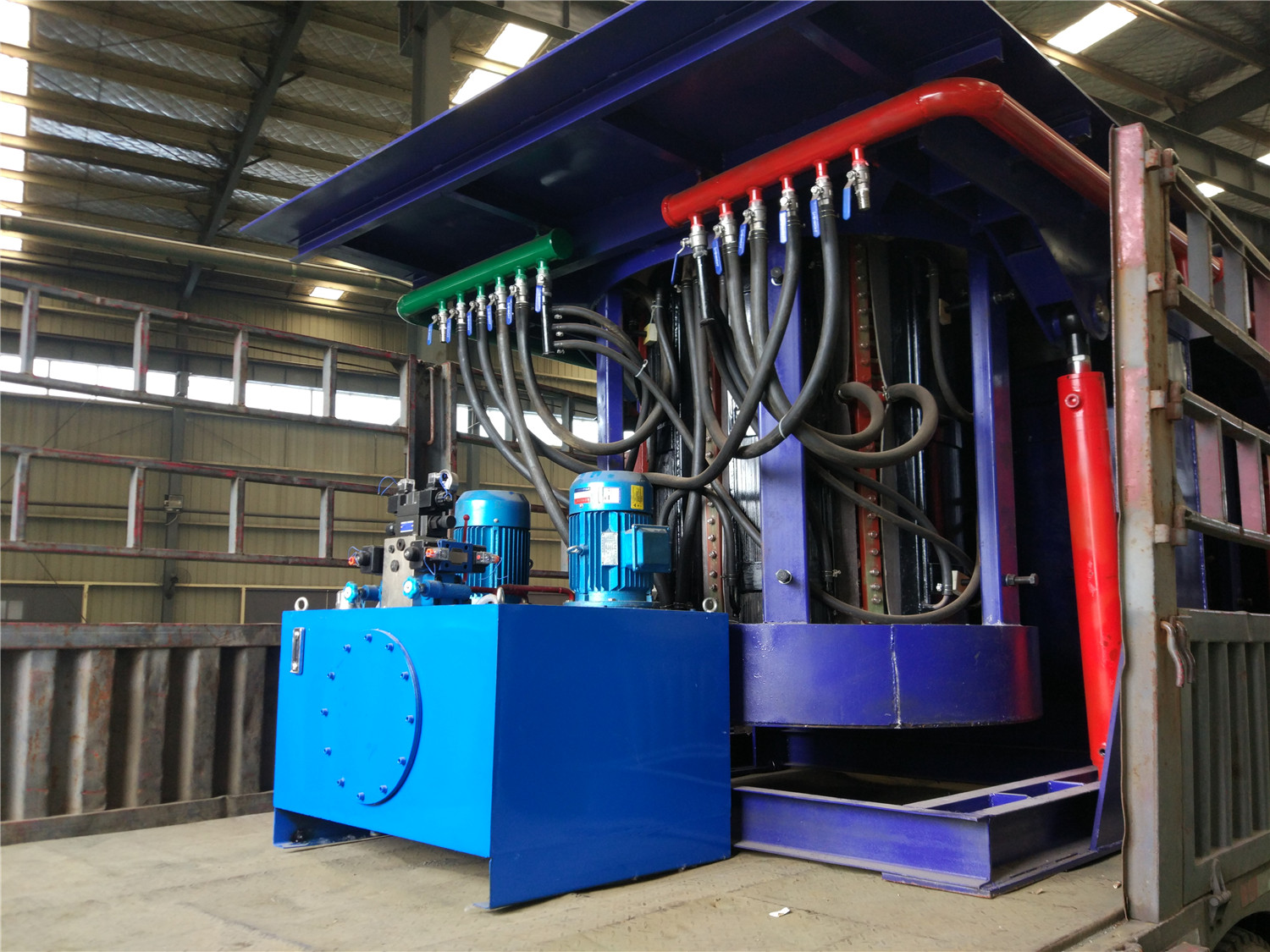
Induction iron furnace
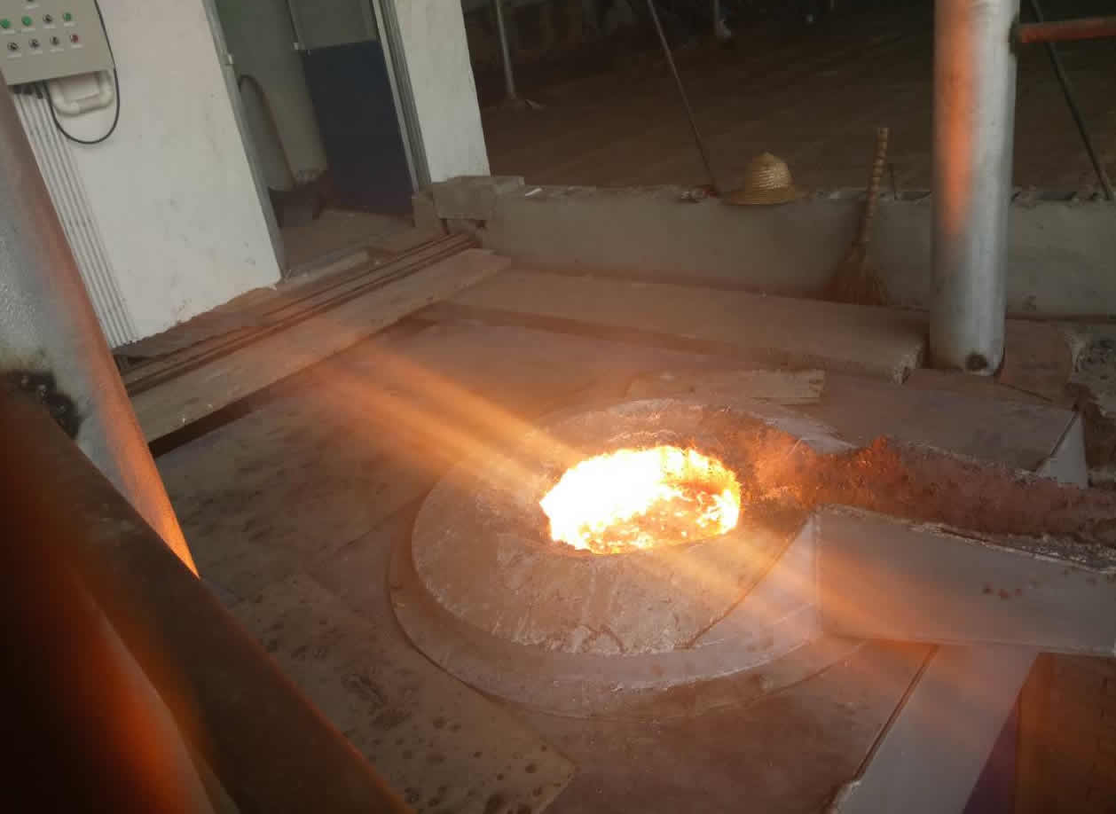
3T intermediate frequency iron melting f
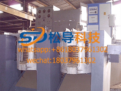
0.25T Intermediate Frequency Furnace
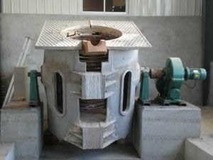
0.5T Intermediate Frequency Furnace
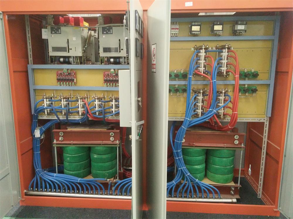
Medium Frequency Furnace

2T Induction Melting Furnace
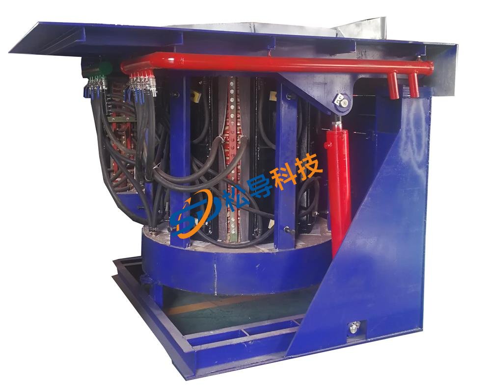
1T Induction Melting Furnace
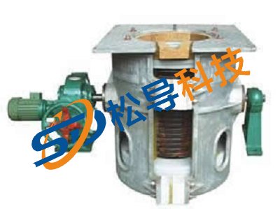
500kg Induction Melting Furnace
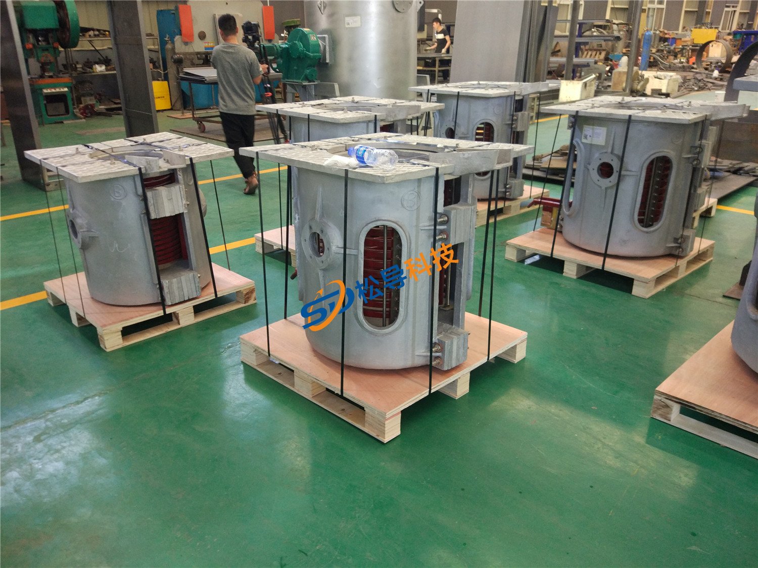
250kg Induction Melting Furnace
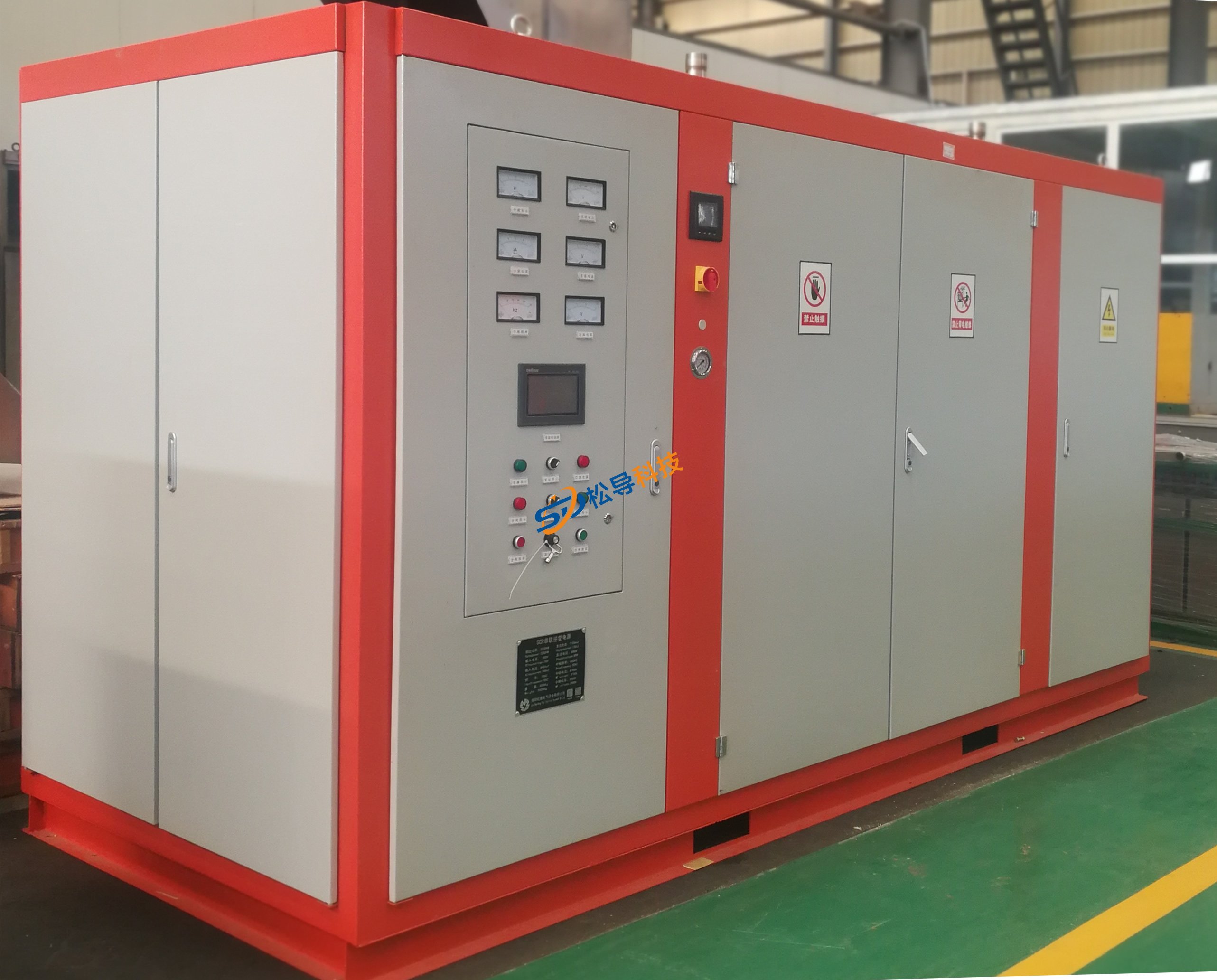
Induction Melting Furnace
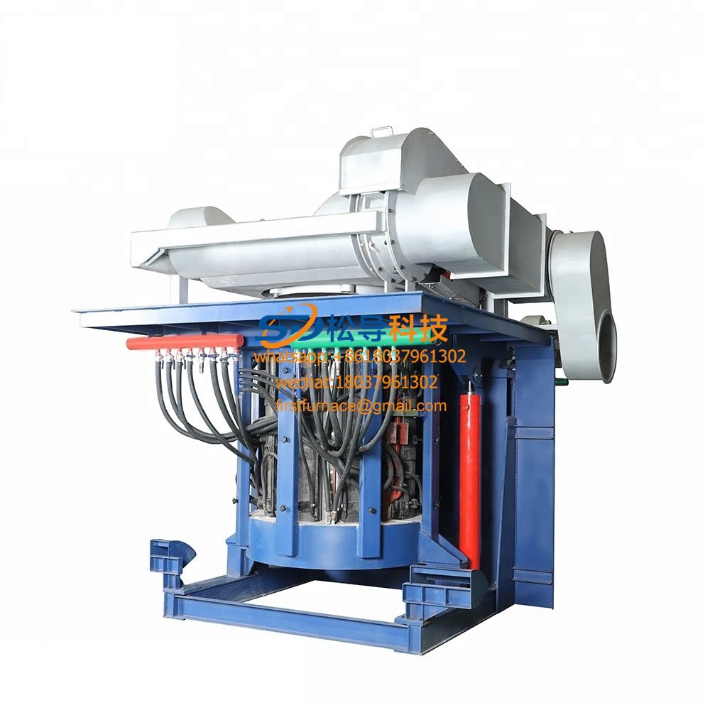
3 T Induction Melting Furnace
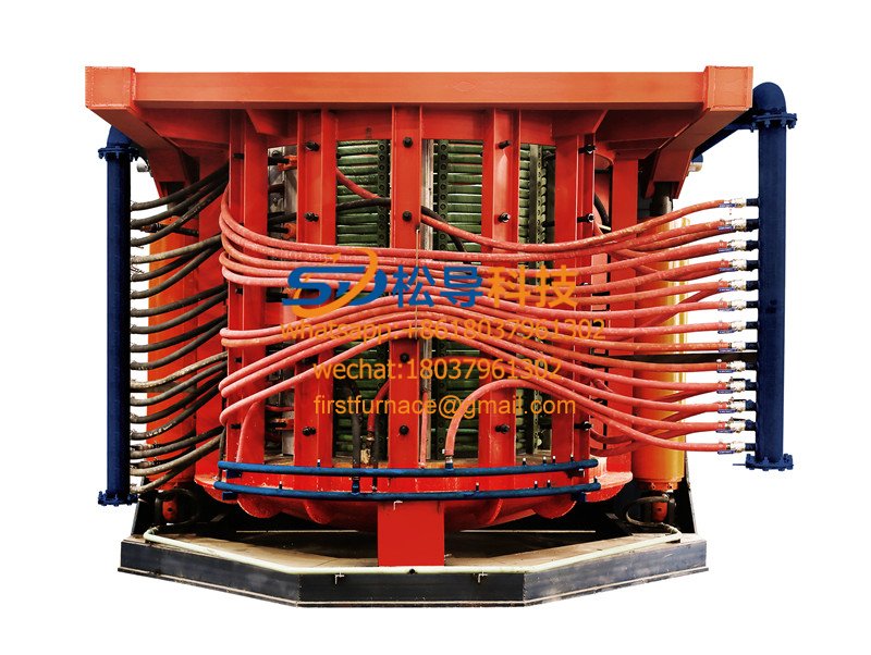
5T Induction Melting Furnace
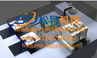
1T One Belt Two Intermediate Frequency F

5T One Belt Two Intermediate Frequency F
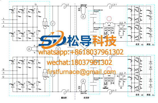
3T One Belt Two Intermediate Frequency F
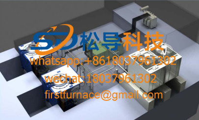
2T One Belt Two Intermediate Frequency F
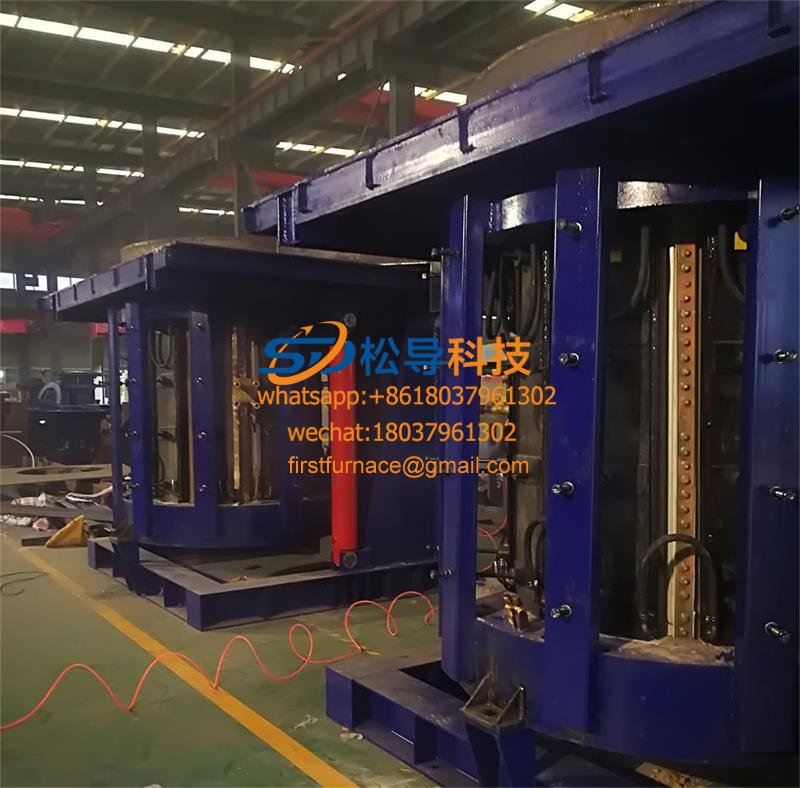
5T Parallel Intermediate Frequency Furna
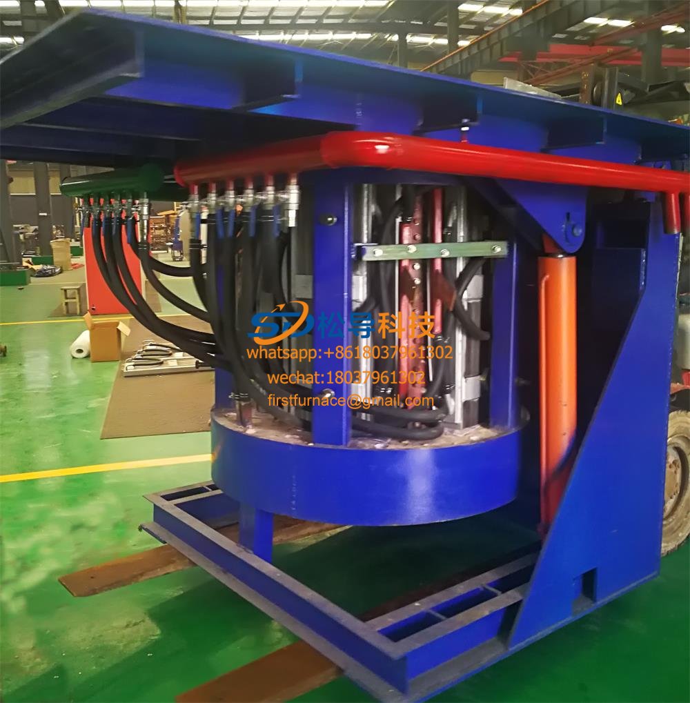
5T Intermediate Frequency Furnace

5T Series Intermediate Frequency Furnace
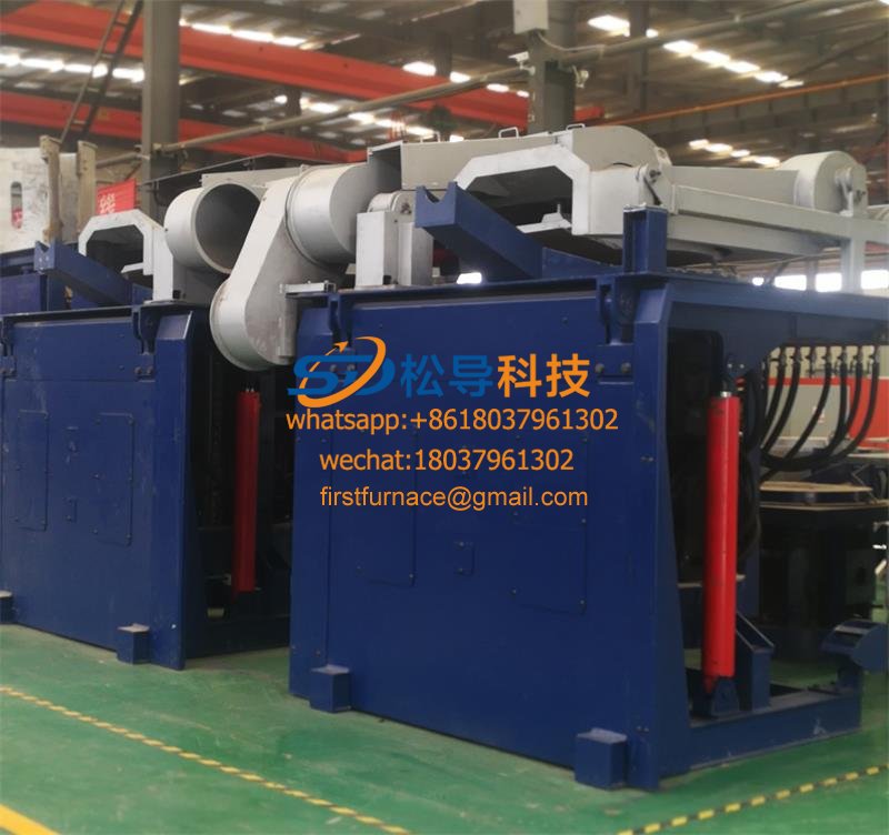
3T Series Intermediate Frequency Furnace
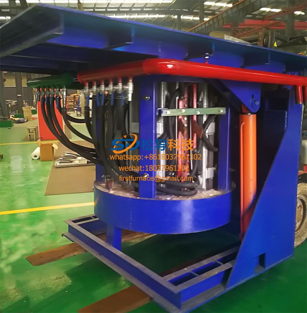
2T Series Intermediate Frequency Furnace
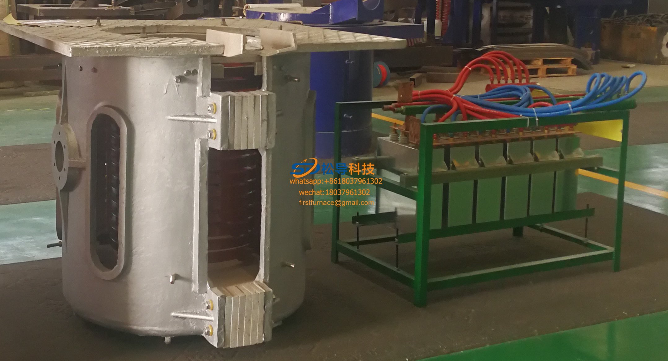
1T Series Intermediate Frequency Furnace
0.5T Series Intermediate Frequency Furna

0.25T Series Intermediate Frequency Furn
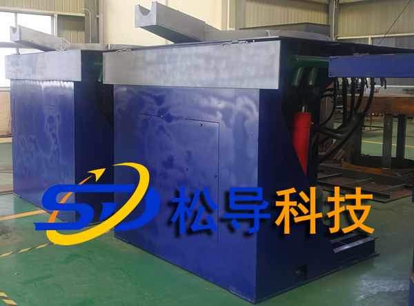
1T Parallel Intermediate Frequency Furna
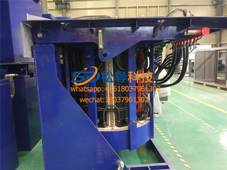
2T Parallel Intermediate Frequency Furna
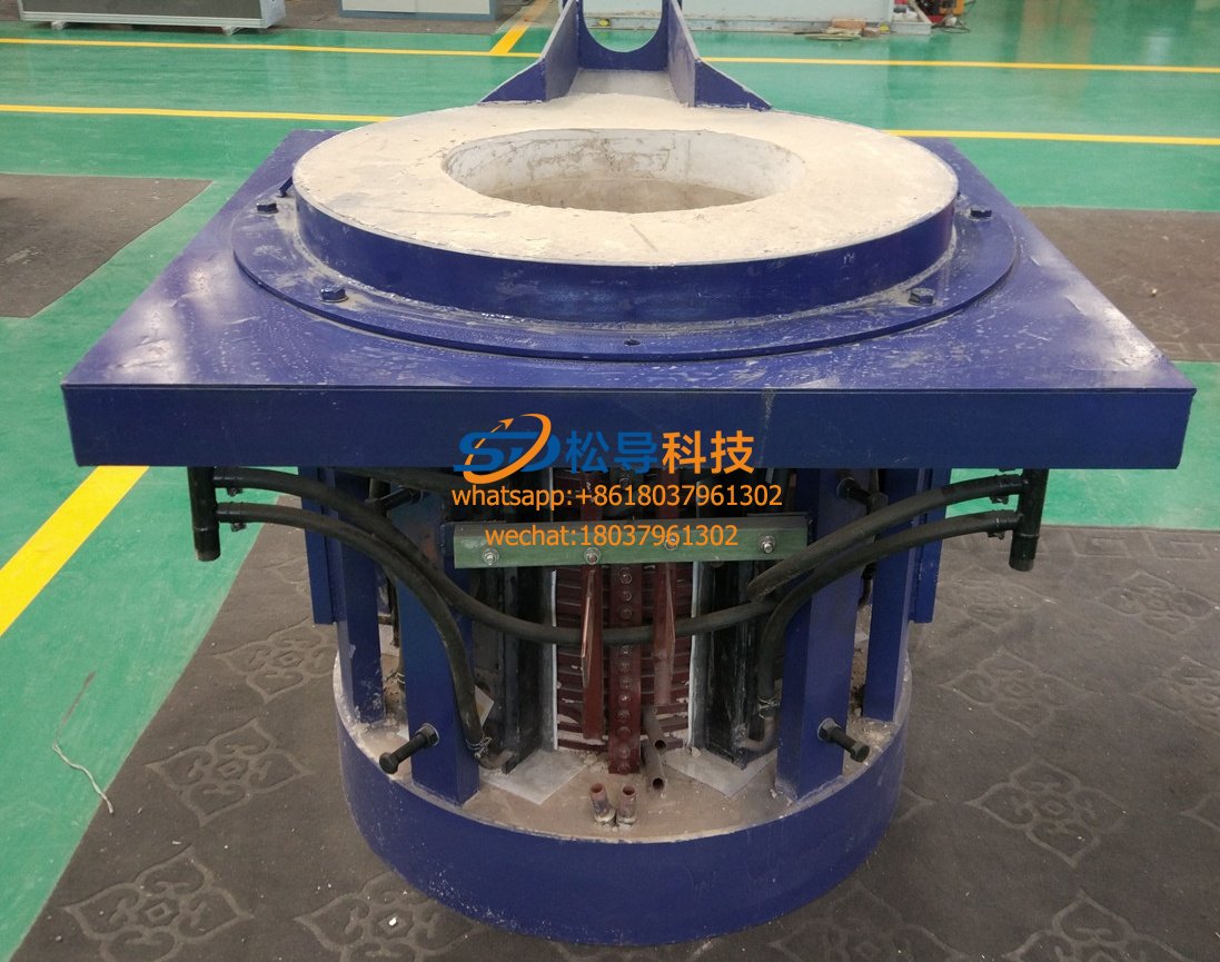
0.5T Parallel Intermediate Frequency Fur


