Sales hot line ( 24 hours service): 18037961302
E-Mail: firstfurnace@gmail.com
whatsapp:+8618037961302
Adress: Luoxin Industrial Park, Luoyang, HenanLarge diameter steel pipe quen
Piston rod quenching and tempe
Grinding rod quenching and tem
High frequency induction heate
Quenching equipment for machin
Round steel end heating furnac
Steel pipe heat treatment prod
Square steel quenching and tem
Sucker rod quenching and tempe
Thickened petroleum steel pipe
Round steel quenching and temp
Steel pipe quenching and tempe
Steel plate quenching and temp
Induction Hardening Machine&nb
Flywheel ring gear high freque
Effective ways to improve the power factor of induction melting furnace
When a>0, the AC current of the induction melting furnace power factor is lagging behind the AC voltage, and the apparent power of the main transformer valve side contains reactive components. The larger the control angle a, the more reactive power will be absorbed from the grid. a = 90. When the reactive power reaches the maximum value. The power factor of the induction melting furnace is a large-scale energy-consuming equipment, and measures to improve the power factor must be taken.
Induction melting furnace rectifier is also a source of harmonics, not only harmonic currents all produce reactive power, but also seriously pollute the power grid. Therefore, the design of the rectifier circuit should also try to improve the measures to reduce harmonics.
There are two effective ways to improve: the valve-side capacitor compensates for reactive power; and the use of a rectifier circuit with less reactive power.
(1) Valve side capacitor compensates reactive power
A parallel capacitor on the valve side compensates for reactive power. However, because of the harmonic current, the ordinary power factor automatic compensation cabinet cannot work normally due to interference, and the capacitor will overheat, and the capacitor protection fuse will blow out abnormally.
The compensation capacitor and the secondary inductance of the transformer may form series resonance for a certain harmonic, causing the compensation capacitor to over-current and over-voltage.
The measure to avoid series resonance is generally to compensate the series inductance of the capacitor. Inductance X%¨Q4%-5%.
Note that the correct selection of inductance X% must be determined by professional measurement of valve side inductance, various harmonics, power factor and other parameters, and then calculation and evaluation. Especially for large-capacity and large-tonnage induction melting furnaces, we must be more cautious.
2) A passive detuning L-C series filter is connected to the valve side. The detuning frequency of the LC series resonant circuit is designed to be 10%-15% lower than the absorbed frequency, and the inductance ratio X%¨Q4%-5%. For example, if the absorbed frequency is the fifth harmonic of 250Hz, the detuning frequency is designed as 225-213 Hz. Designed as a detuning filter, the main purpose is to perform power factor compensation, followed by absorption of harmonic currents.
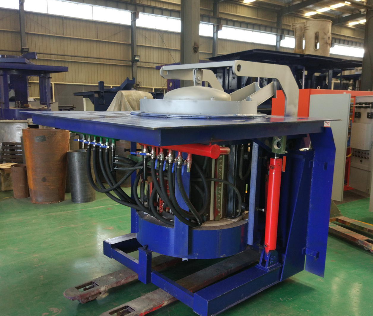
Iron induction furnace
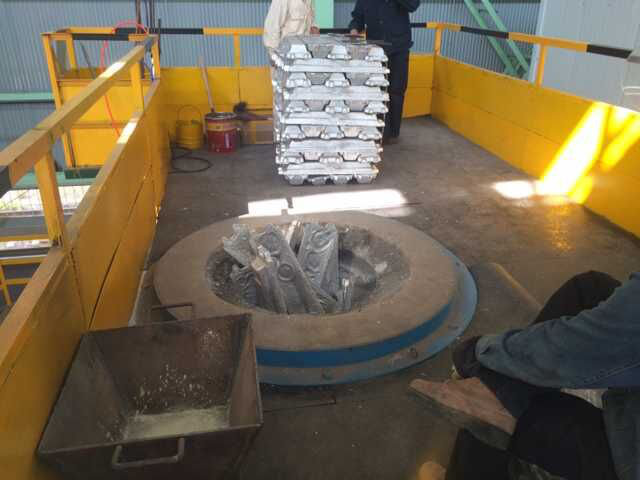
Aluminum melting furnace
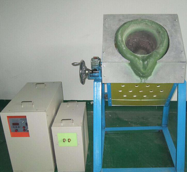
Copper melting furnace
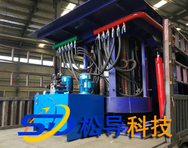
Small steel melting furnace
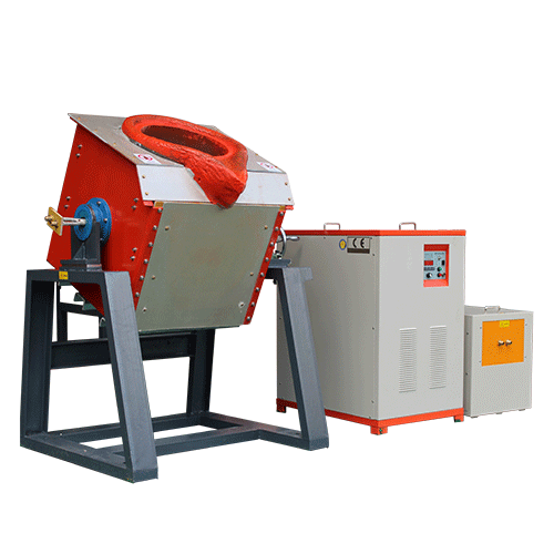
Small induction melting furnace
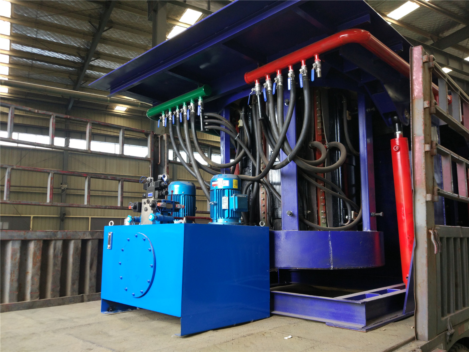
Induction iron furnace
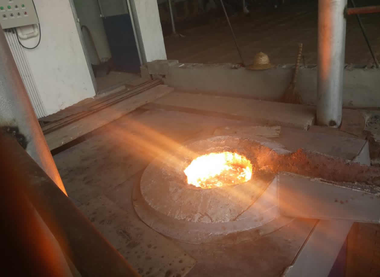
3T intermediate frequency iron melting f
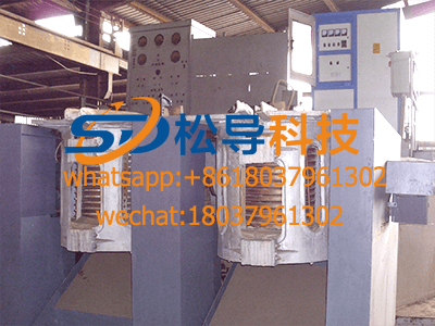
0.25T Intermediate Frequency Furnace
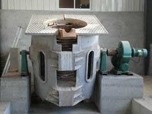
0.5T Intermediate Frequency Furnace
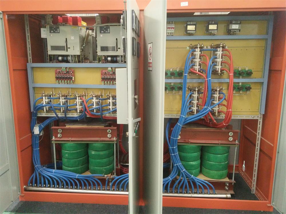
Medium Frequency Furnace

2T Induction Melting Furnace
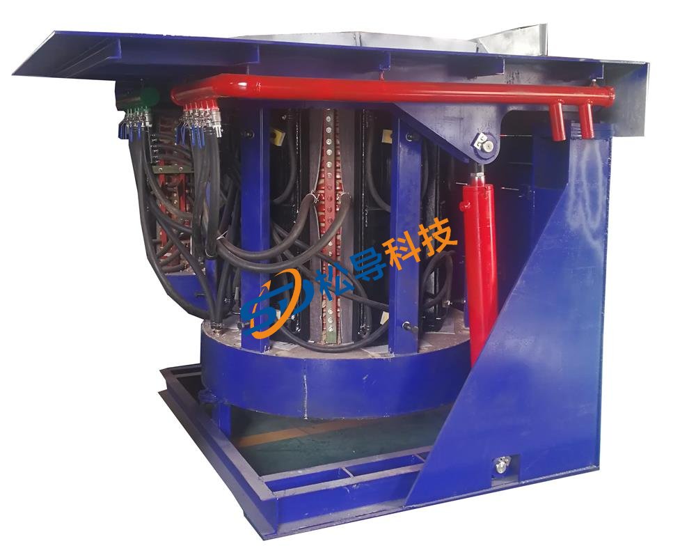
1T Induction Melting Furnace
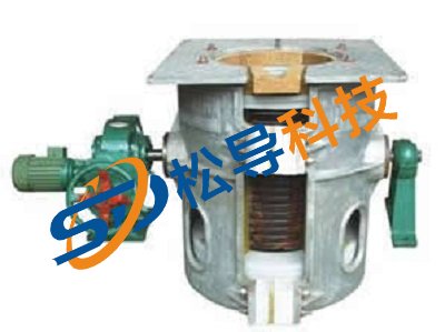
500kg Induction Melting Furnace
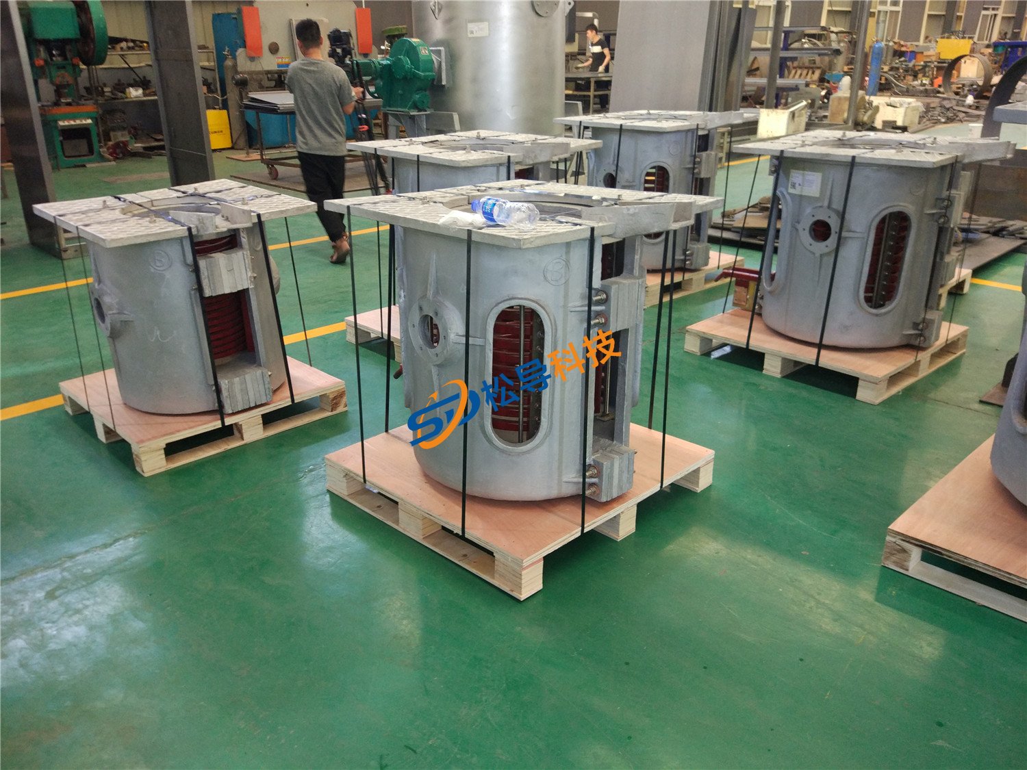
250kg Induction Melting Furnace
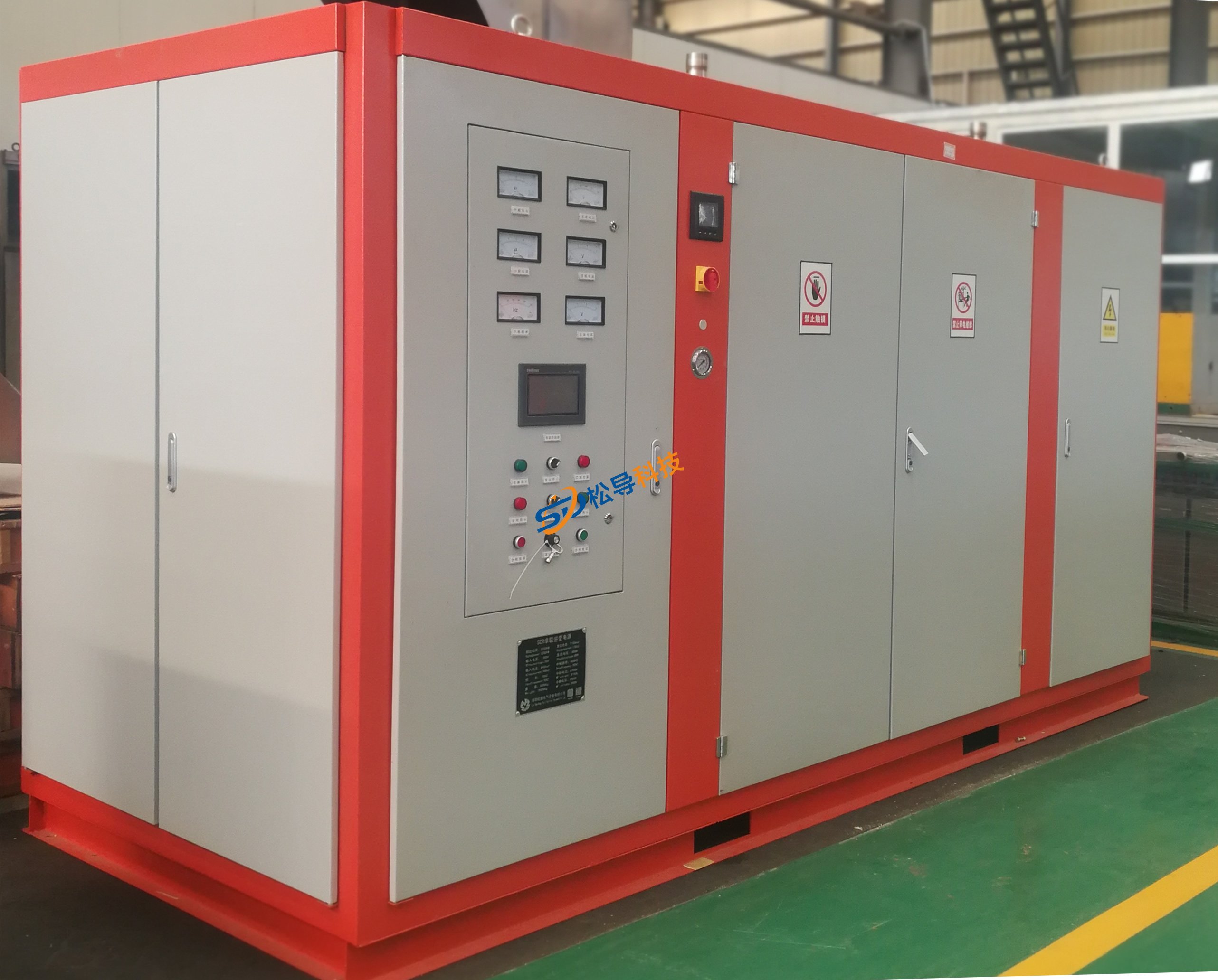
Induction Melting Furnace
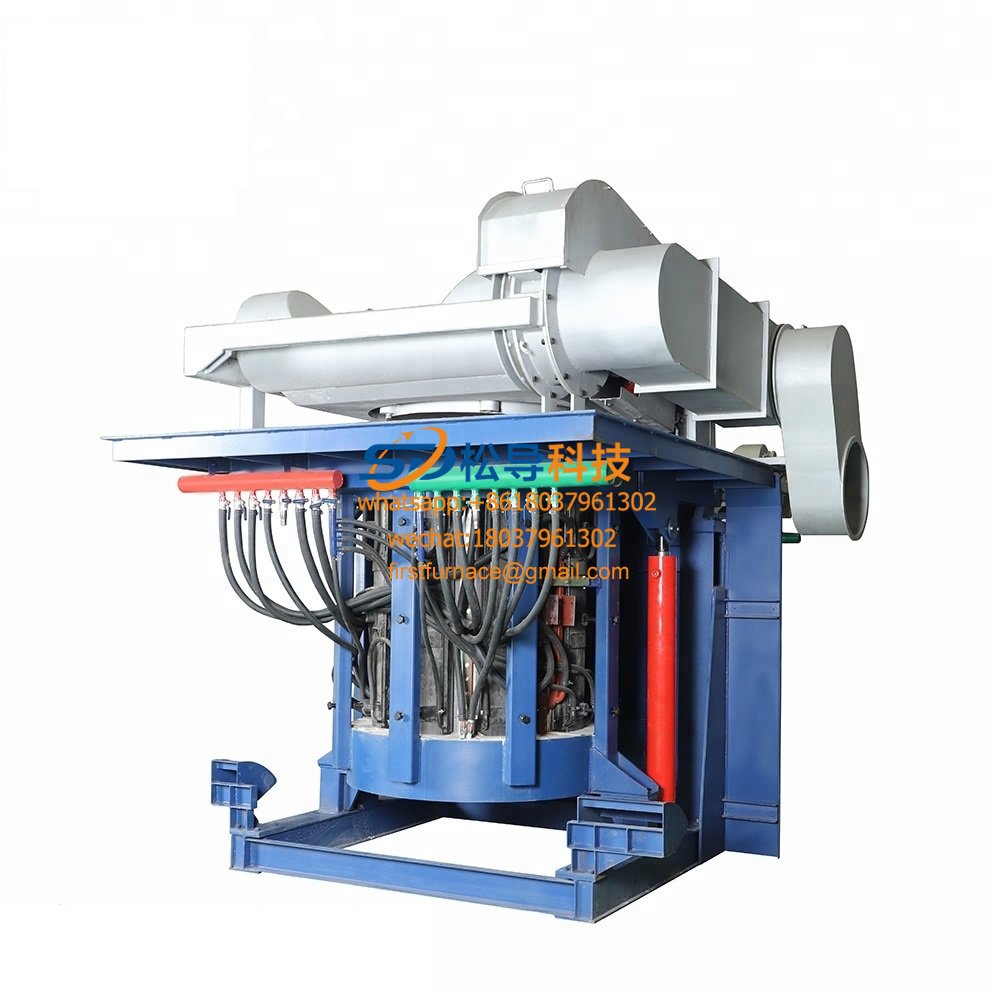
3 T Induction Melting Furnace
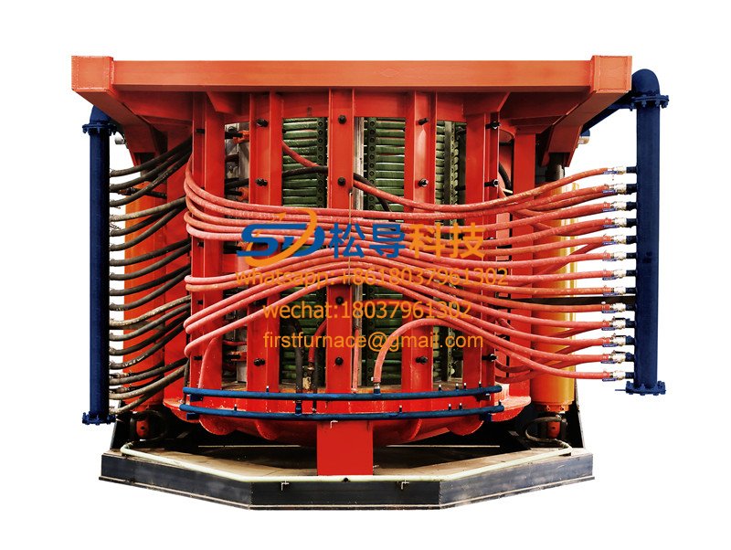
5T Induction Melting Furnace
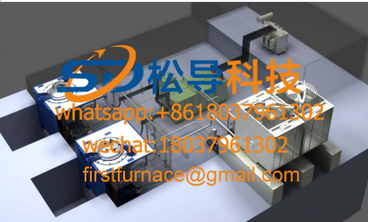
1T One Belt Two Intermediate Frequency F

5T One Belt Two Intermediate Frequency F
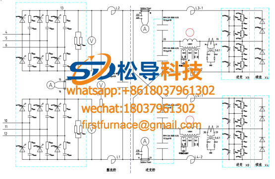
3T One Belt Two Intermediate Frequency F
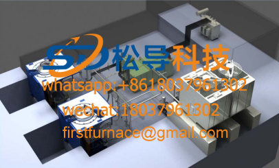
2T One Belt Two Intermediate Frequency F
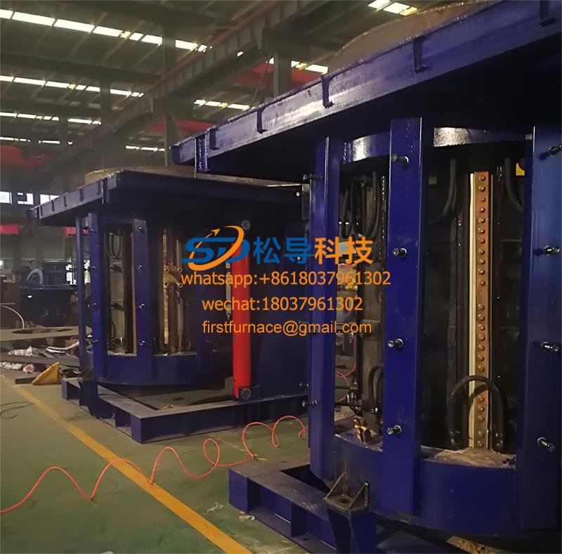
5T Parallel Intermediate Frequency Furna
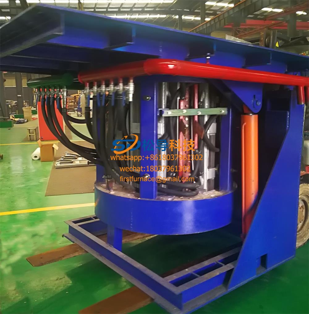
5T Intermediate Frequency Furnace

5T Series Intermediate Frequency Furnace
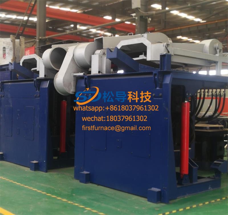
3T Series Intermediate Frequency Furnace
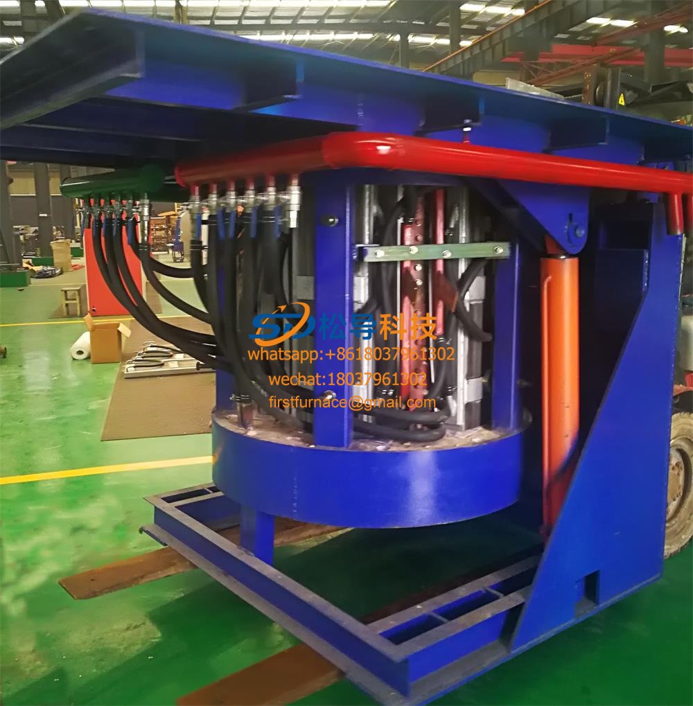
2T Series Intermediate Frequency Furnace
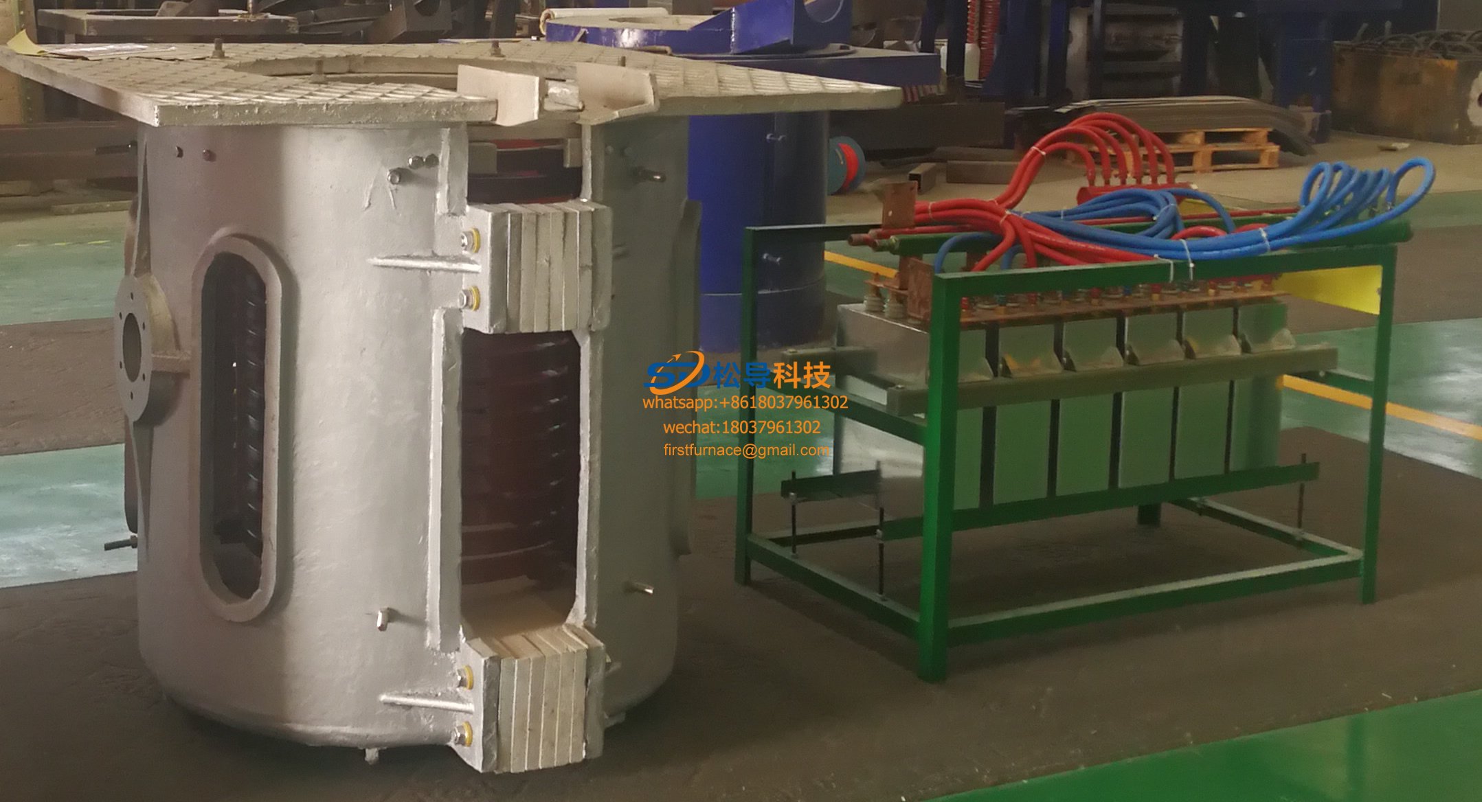
1T Series Intermediate Frequency Furnace
0.5T Series Intermediate Frequency Furna

0.25T Series Intermediate Frequency Furn
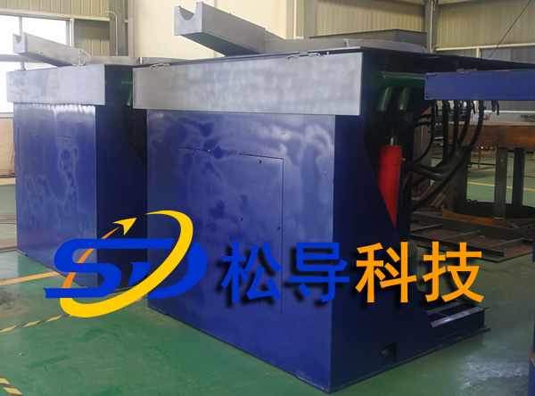
1T Parallel Intermediate Frequency Furna
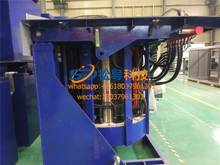
2T Parallel Intermediate Frequency Furna
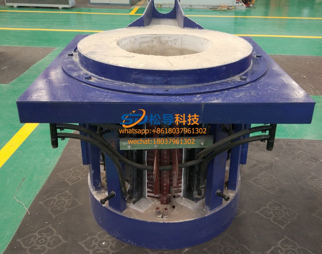
0.5T Parallel Intermediate Frequency Fur


