Sales hot line ( 24 hours service):+86 13015583380
E-Mail: firstfurnace@gmail.com
whatsapp:+86 13015583380
Adress: Luoxin Industrial Park, Luoyang, HenanLarge diameter steel pipe quen
Piston rod quenching and tempe
Grinding rod quenching and tem
High frequency induction heate
Quenching equipment for machin
Round steel end heating furnac
Steel pipe heat treatment prod
Square steel quenching and tem
Sucker rod quenching and tempe
Thickened petroleum steel pipe
Round steel quenching and temp
Steel pipe quenching and tempe
Steel plate quenching and temp
Induction Hardening Machine&nb
Flywheel ring gear high freque
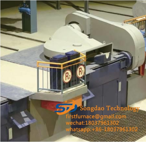
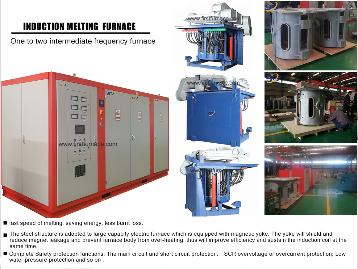
The hydraulic system of the induction melting furnace is mainly composed of three parts: a hydraulic pump station, a cabinet console and an electrical control cabinet. Pressure regulating filter and other devices; adopt horizontal motor-pump external structure. Two sets of units have one set of work and one set of standby, which realizes the automatic control of electric furnace production. The equipment is electro-hydraulic integration, its work is reliable, the performance is stable, and the appearance is beautiful. It has the characteristics of good sealing and strong anti-pollution ability. Compared with imported equipment, it has the advantages of low cost and convenient maintenance.
A. Main performance parameters
1. Maximum working pressure 16Mpa
2. Working pressure 9Mpa
3. Working flow 23.2 L/min
4. Input power 7.5kw
5. Fuel tank capacity 0.6M3
B. Working principle and operation, adjustment
Operation, adjustment
The hydraulic operating table of this system integrates pressure display, furnace tilting, furnace cover opening and closing, and hydraulic pump opening (closing). Switch the hydraulic pump such as: turn on the No. 1 pump, turn on the green button of the No. 1 pump, turn off the pump, turn on the red button of the No. 1 pump, start the hydraulic pump, and step on the foot switch QTS; then, slowly rotate clockwise and evenly rotate the electromagnetic overflow The pressure regulating hand wheel of the valve adjusts the working pressure of the system to the required value (the pressure gauge displays and the lock nut of the pressure regulating hand wheel is locked to prevent the loosening of the hand wheel and affecting production).
After the pressure gauge on the valve station shows the working pressure, the equipment can work normally.
Step on the foot switch and the pump will automatically load.
Move the joystick to the “up” position such as tilting the furnace.
C. The furnace body is reset to move the joystick to the “down” position. The tilting speed of the furnace can be adjusted by adjusting the MK-type one-way throttle valve to adjust the rising speed of the furnace body and the falling speed of the furnace body.
Furnace lid open and close
Opening procedure: First pull the lift valve stem in the up position, and then pull the rotating valve stem in the open position.
Closing procedure: first pull the rotary valve stem in the closed position, and then pull the lift valve stem in the lower position.
D. Matters needing attention
Lifting and installation
When lifting hydraulic pump stations, fuel tanks, and cabinet valve stations, use lifting rings to prevent damage to the equipment and paint surfaces.
After installation, all connecting screws should be checked in time. If there is any looseness during transportation, they should be tightened clearly to avoid accidents.
Pay attention to the direction of rotation of the motor, and ensure that the hydraulic pump rotates clockwise from the end of the motor shaft.
E. Use and maintenance
The working medium used in this hydraulic station is L-HM46 hydraulic oil, and the normal oil temperature should be within the range of 10℃-50℃;
The fuel tank should be filled from the air filter on the fuel tank using an oil filter truck (new fuel must also be filtered);
The oil level in the tank should be within the range of the uppermost level gauge, and the lowest level during use shall not be lower than the lowest position of the level gauge;
After all the equipment is installed, the entire system must be flushed thoroughly according to the cleaning plan to remove iron filings and other debris remaining on the inner wall of the pipeline to ensure the normal operation of the equipment. The equipment is not allowed to be put into production without washing treatment to avoid accidents;
F. Repair
It is recommended to clean the oil suction filter once half a year, and clean the oil return filter;
It is recommended that hydraulic equipment be overhauled once a year and the oil should be replaced;
During the production process, if oil leakage is found in the manifold, hydraulic components, pipe joints, hydraulic valve stations, hydraulic cylinders or hose joints, stop the machine in time and replace the seals.
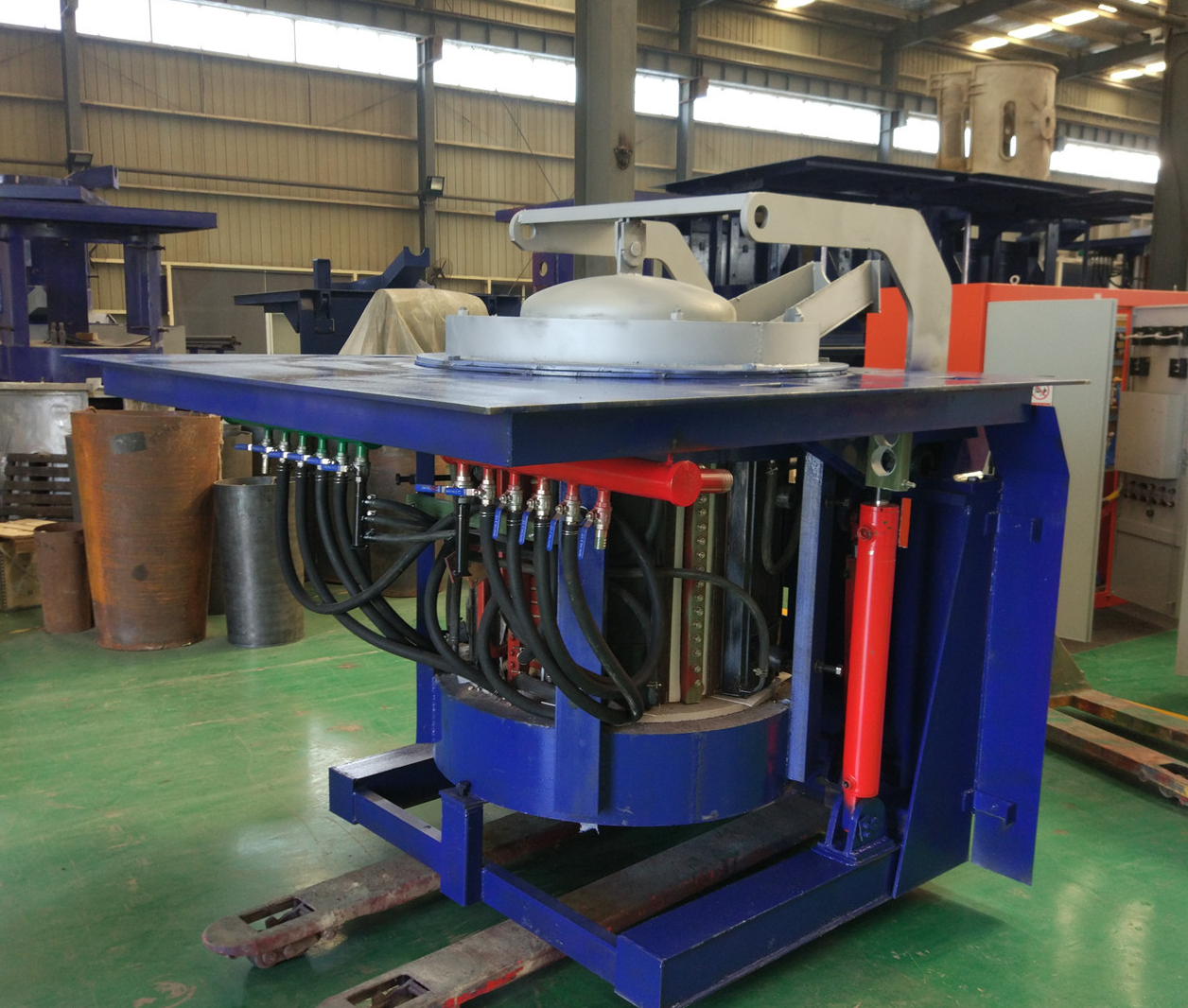
Iron induction furnace
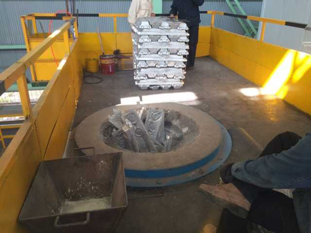
Aluminum melting furnace
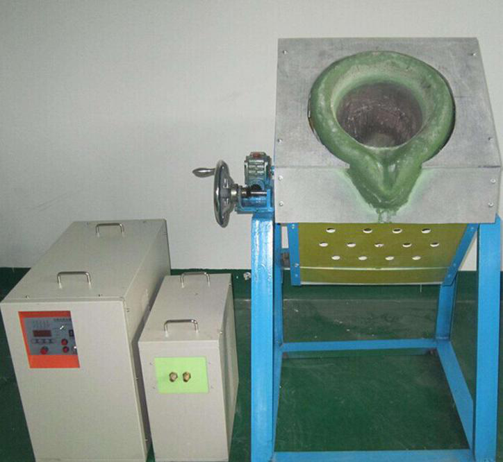
Copper melting furnace
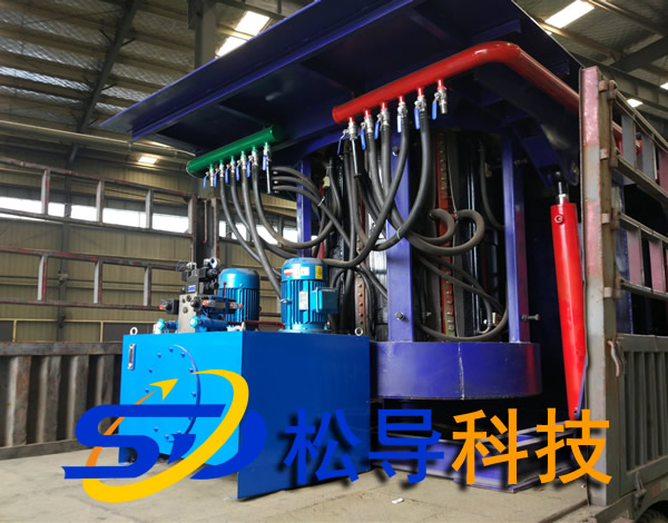
Small steel melting furnace
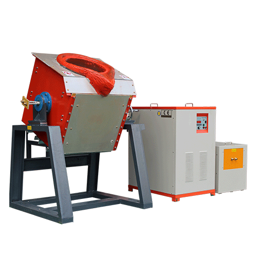
Small induction melting furnace
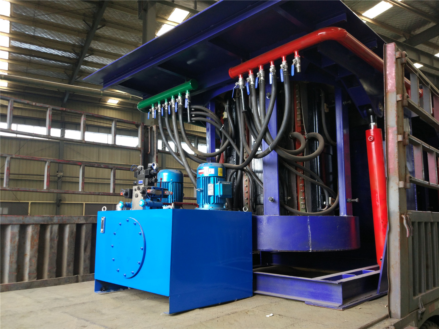
Induction iron furnace
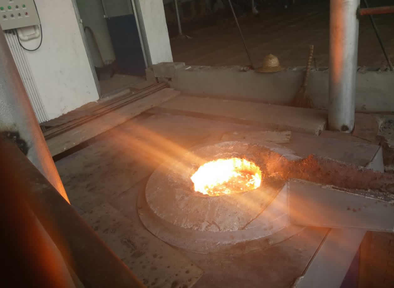
3T intermediate frequency iron melting f
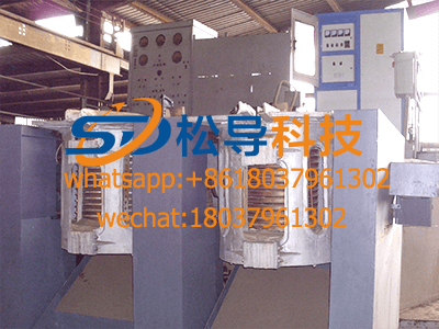
0.25T Intermediate Frequency Furnace
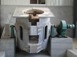
0.5T Intermediate Frequency Furnace
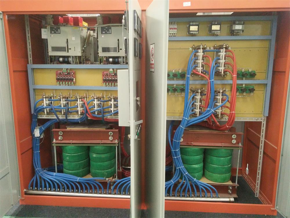
Medium Frequency Furnace

2T Induction Melting Furnace
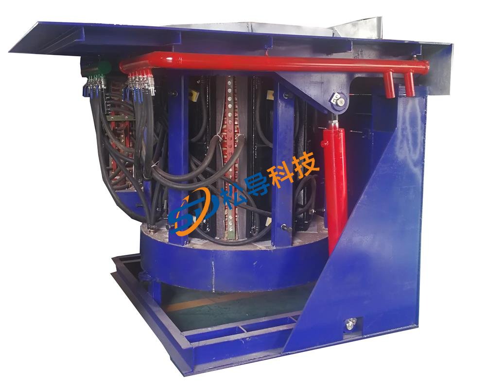
1T Induction Melting Furnace
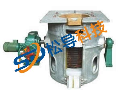
500kg Induction Melting Furnace
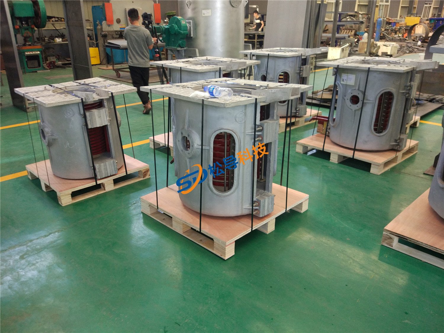
250kg Induction Melting Furnace
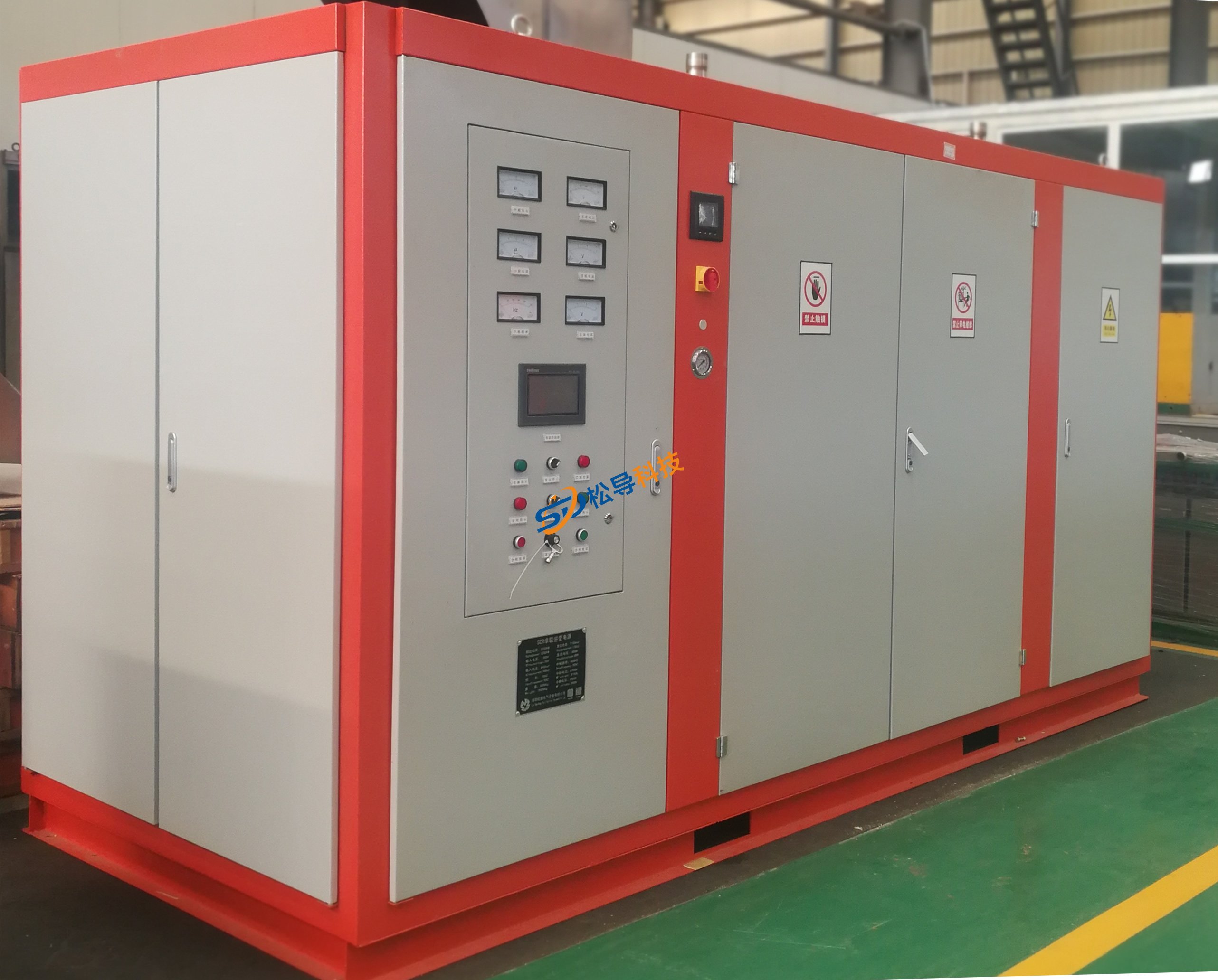
Induction Melting Furnace
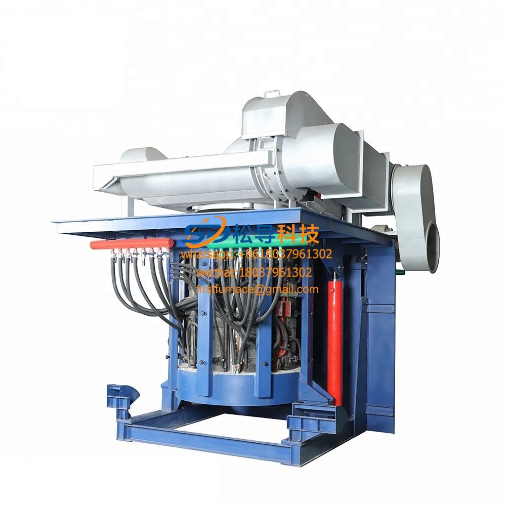
3 T Induction Melting Furnace
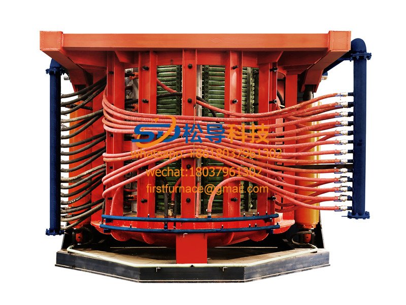
5T Induction Melting Furnace
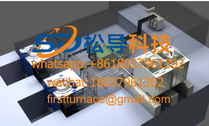
1T One Belt Two Intermediate Frequency F

5T One Belt Two Intermediate Frequency F
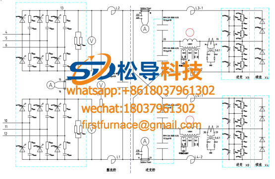
3T One Belt Two Intermediate Frequency F
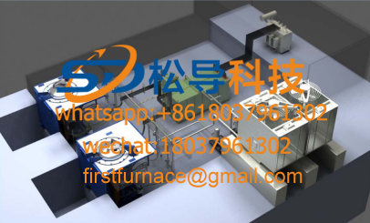
2T One Belt Two Intermediate Frequency F
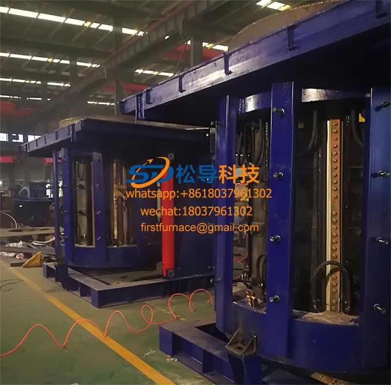
5T Parallel Intermediate Frequency Furna
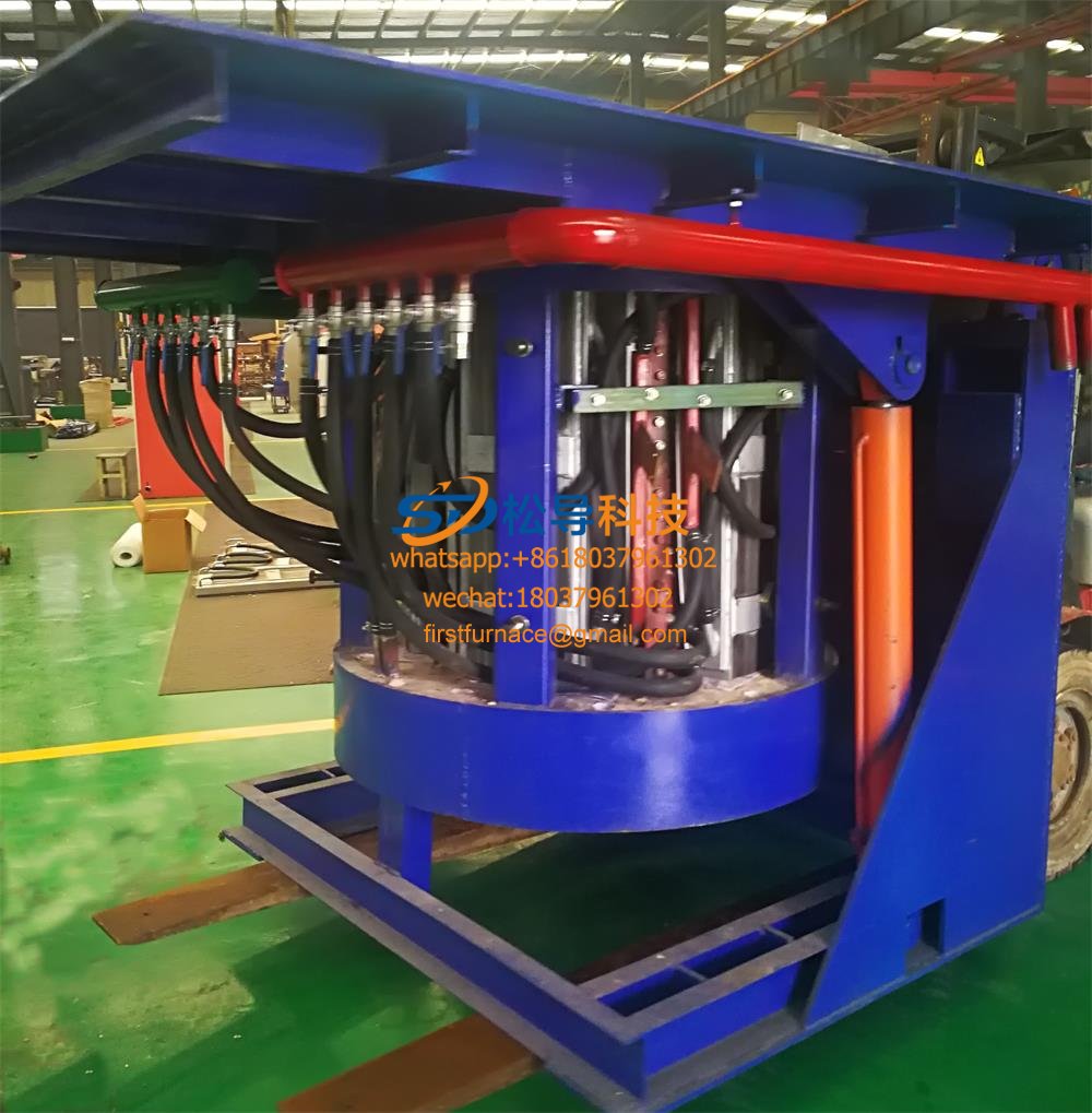
5T Intermediate Frequency Furnace

5T Series Intermediate Frequency Furnace
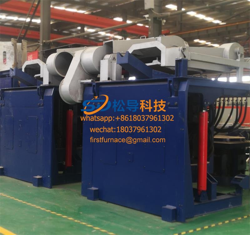
3T Series Intermediate Frequency Furnace
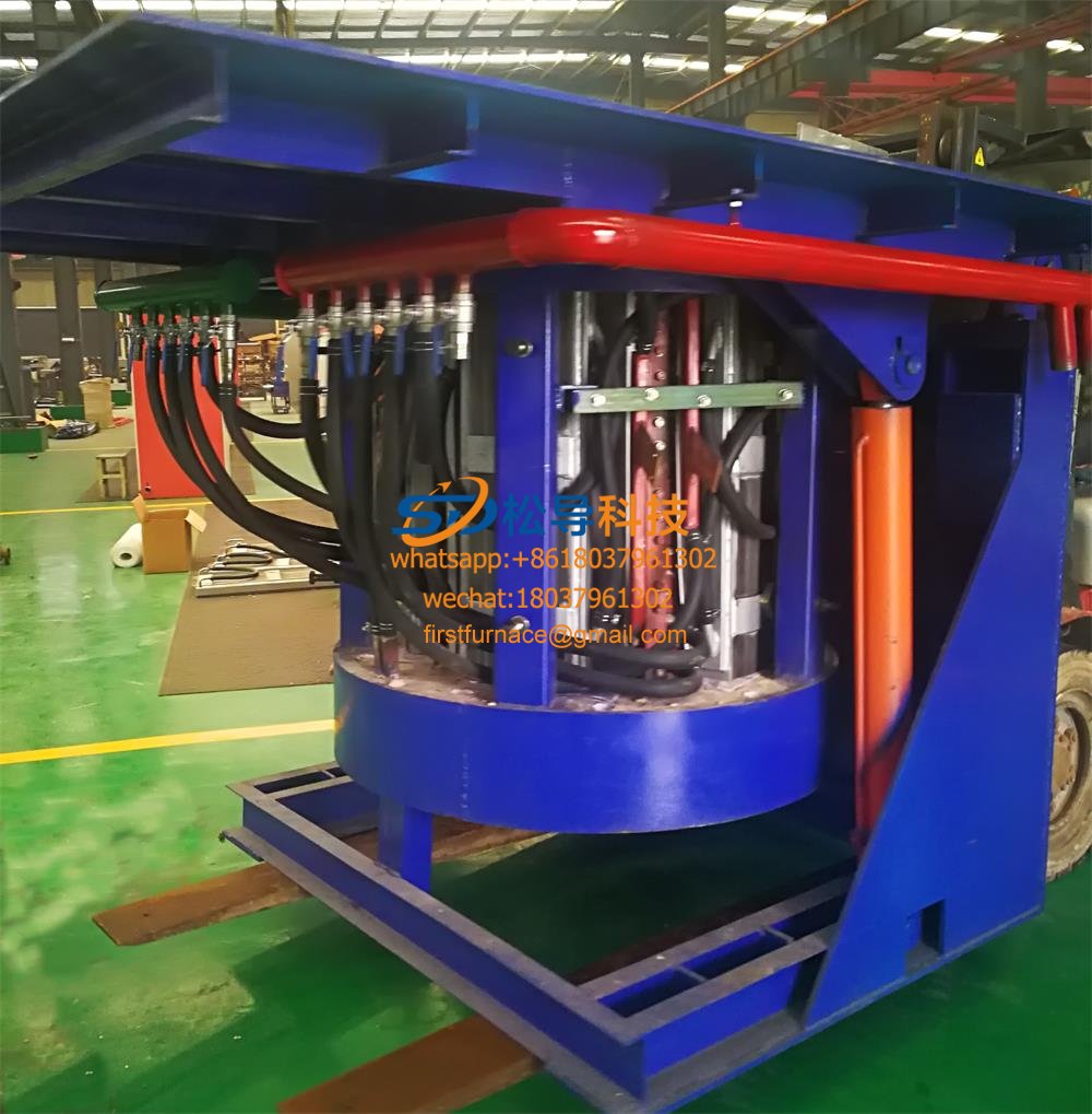
2T Series Intermediate Frequency Furnace
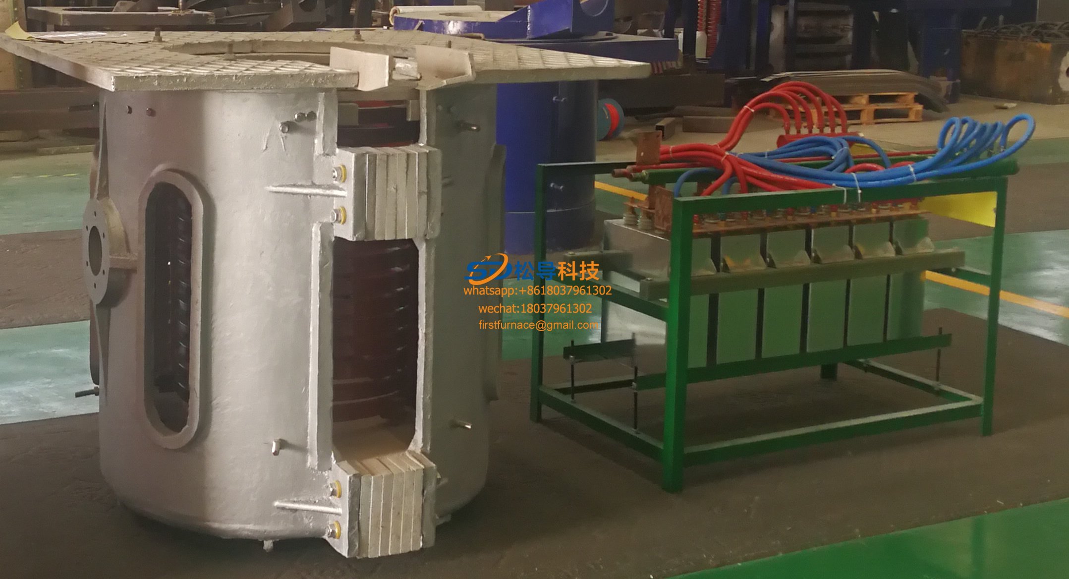
1T Series Intermediate Frequency Furnace
0.5T Series Intermediate Frequency Furna

0.25T Series Intermediate Frequency Furn
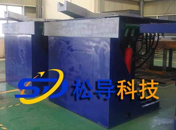
1T Parallel Intermediate Frequency Furna
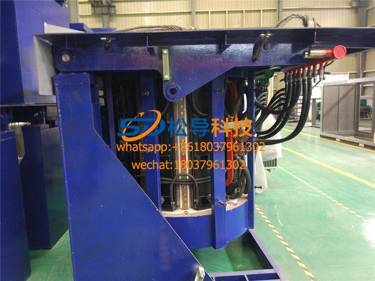
2T Parallel Intermediate Frequency Furna
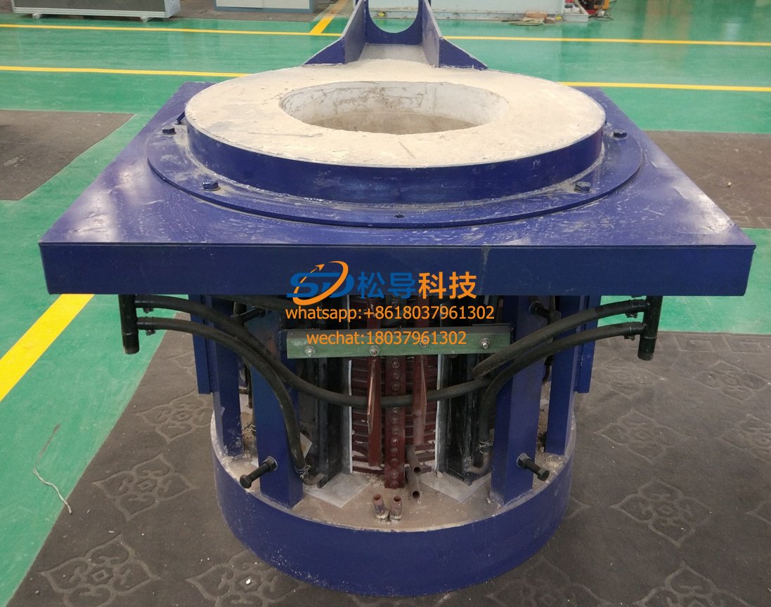
0.5T Parallel Intermediate Frequency Fur


