Sales hot line ( 24 hours service): 18037961302
E-Mail: firstfurnace@gmail.com
whatsapp:+8618037961302
Adress: Luoxin Industrial Park, Luoyang, HenanLarge diameter steel pipe quen
Piston rod quenching and tempe
Grinding rod quenching and tem
High frequency induction heate
Quenching equipment for machin
Round steel end heating furnac
Steel pipe heat treatment prod
Square steel quenching and tem
Sucker rod quenching and tempe
Thickened petroleum steel pipe
Round steel quenching and temp
Steel pipe quenching and tempe
Steel plate quenching and temp
Induction Hardening Machine&nb
Flywheel ring gear high freque
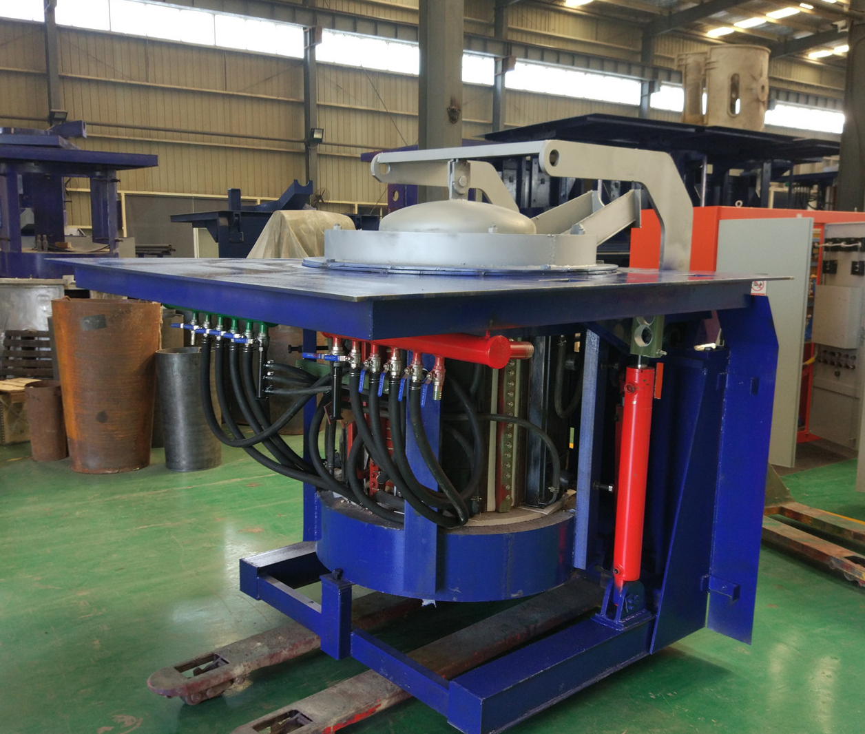
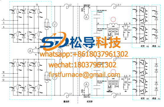
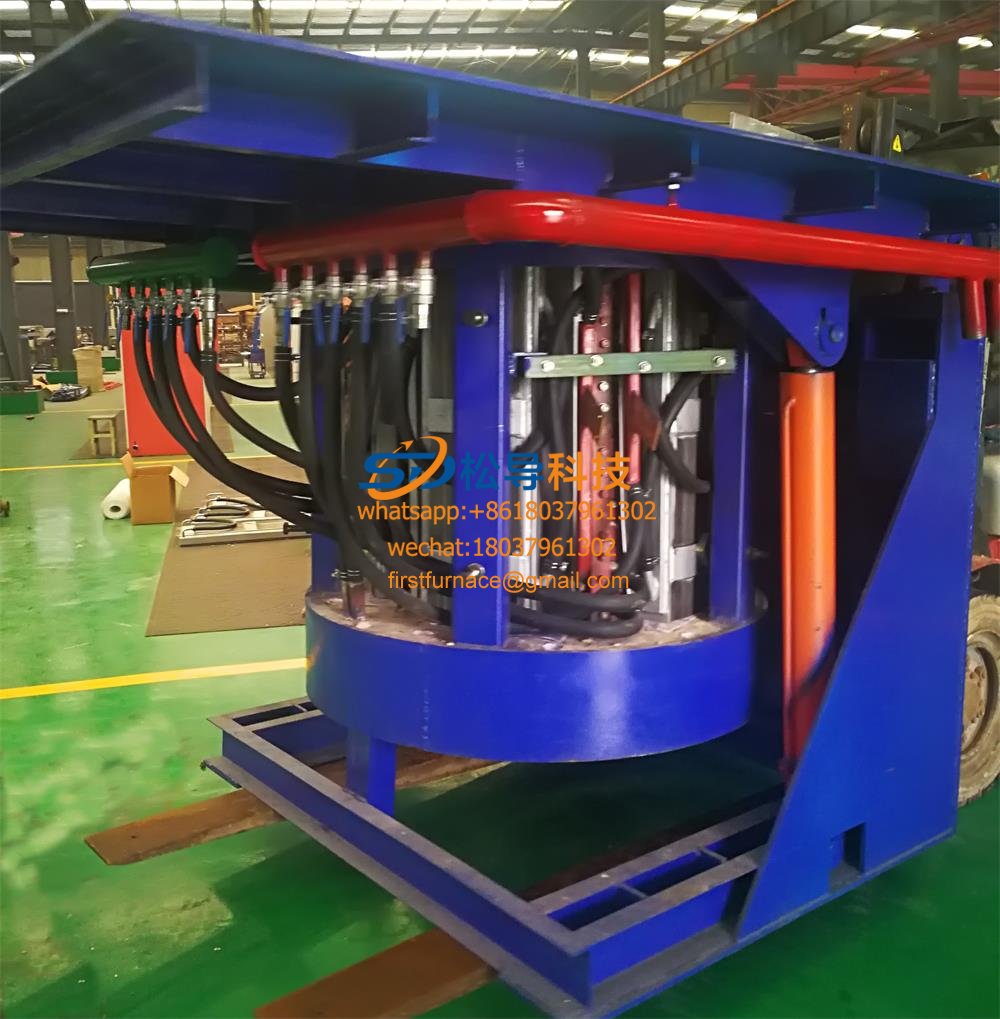
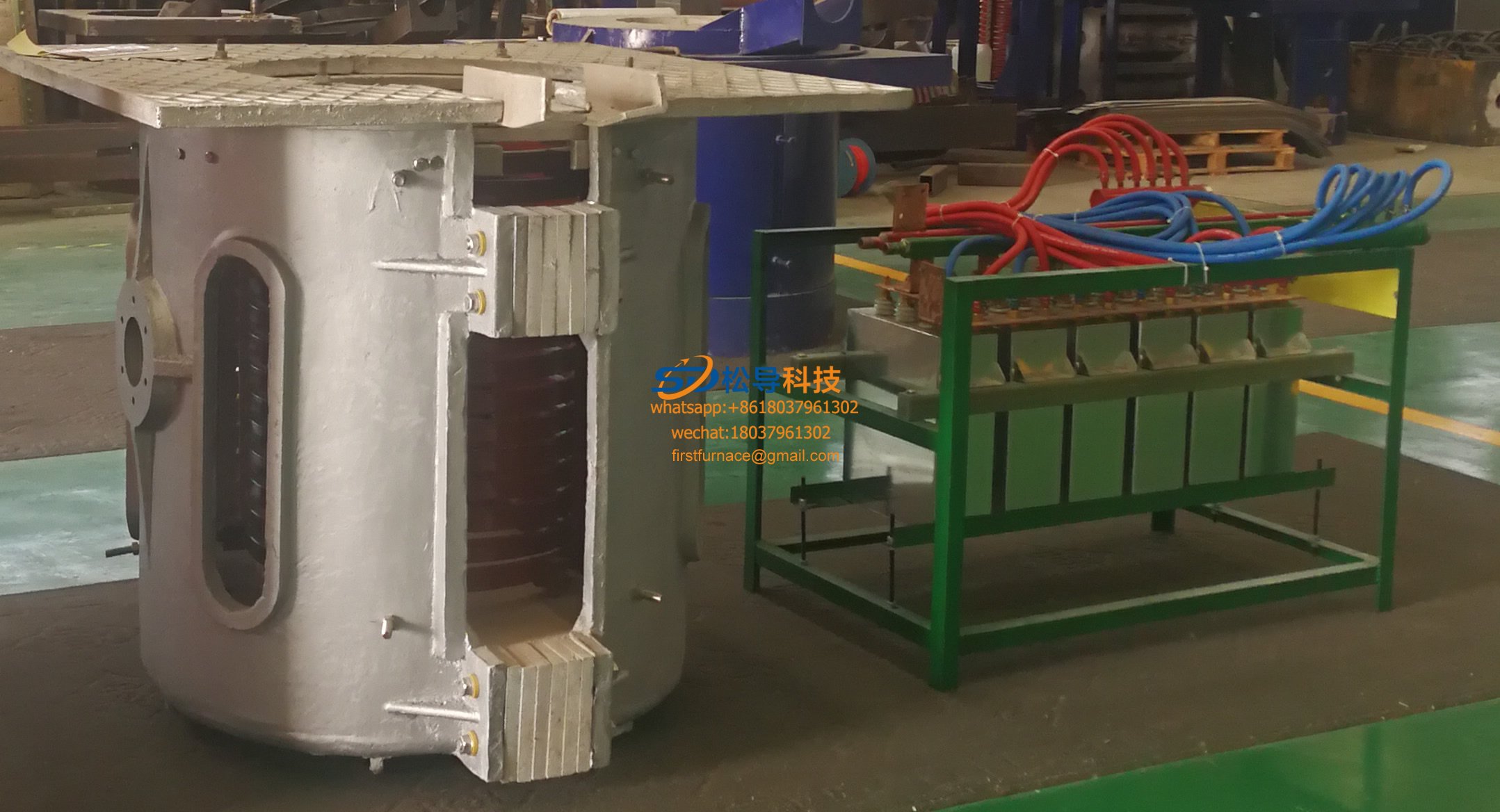
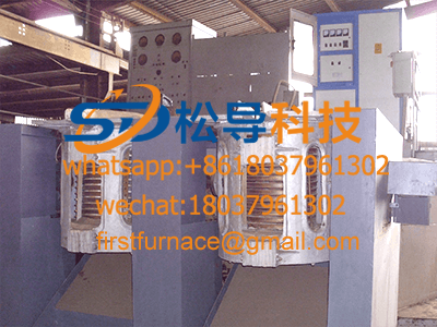
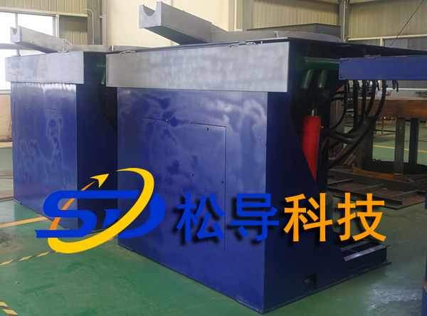
Inverter circuit common failure of induction melting furnace
IF power does not go up
The induction melting furnace can only work at low power. When the DC voltage Ud is raised, the overcurrent protection action. The cause of the fault is that the load AC equivalent resistance is too small. Especially when the furnace reaches the later stage, the thickness of the lining is reduced. After starting, the DC voltage is small, the current is large, the intermediate frequency voltage is also small, the commutation is difficult, the inverter is easy to subvert, and the power is not up. At this time, the tf is appropriately increased. Increase the current signal ceramic potentiometer. After the charge is melted, the ic is restored to the normal value. In addition, the induction coil has poor insulation between the turns, and can work when the voltage is low. When the intermediate frequency voltage is high, the insulation breakdown causes a short circuit between the turns, and the AC equivalent resistance is rapidly reduced, and the inverter is easily subverted. The solution is to get rid of the lining and make the insulation of the induction coil normal.
Both the DC voltage and the IF voltage are high, while the DC current is small. When the DC voltage rises to the maximum, the IF power is still low. The reason for the failure is that the new furnace lining furnace wall is thicker and the load AC equivalent resistance is too large, then the Ud is large after starting, the Id is small, and the intermediate frequency device cannot satisfy the power output. At this time, the capacity of the compensation capacitor should be increased to match the equivalent resistance.
Equipment startup difficulties
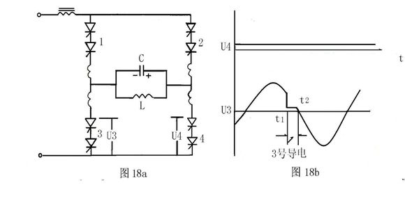
A fault occurs at a lower power, the intermediate frequency voltage is several times higher than the DC voltage, the current is large, the machine emits a lower frequency sound, and the power meter indication is very low. The cause of this failure is caused by a continuous or short circuit of a group of thyristors in the inverter bridge. Especially older IF devices are most prone to this phenomenon. We assume from Figure 18a that the No. 4 bridge arm is closed, and the waveform of the SCR voltage U4 of the No. 4 bridge is a straight line, as shown in Figure 18b. At this time, the bridge arms of No.1 and No.2 can be normally commutated, and the waveform is normal. The waveform of the thyristor voltage U3 of the No.3 bridge arm is as shown in Figure 18b. At the time of t1, the bridge arm conducts electricity. It is reasonable to say that it should be conductive half. Cycle, but since the load IF voltage changes direction after time t2, the polarity of the load voltage after t2 is as shown in Figure 18a, and the bridge arm is closed again, so the bridge arm of the 3rd is blocked by the reverse voltage at time t2. Therefore, No. 3 is only conducting electricity during t1~t2, and after No. 3 is turned off at t2, since the No. 4 is always conducting, the U3 voltage is the load intermediate frequency voltage waveform. The waveform of the No. 3 bridge arm is caused by the continuous or short circuit of the No. 4 switch. It should not be mistaken for the SCR of the No. 3 bridge arm. This kind of fault is often caused by a thyristor switch in advance, and then another thyristor connected in series on the bridge arm is subjected to full voltage, so the switching loss is increased, the temperature rise is increased, and the turn-off time is lengthened, causing the thyristor to be turned off continuously.
Reluctant to work when power is low
However, the IF frequency is reduced, the voltage is low, and the current is large. When the power is increased, the inverter fails and the overcurrent protection action. This type of fault is usually one of the two thyristors connected in series in the bridge arm that is non-conducting, and the entire bridge arm is not conductive. As you can see from the oscilloscope, see Figure 19. If the No. 3 bridge arm is not connected, the No. 4 bridge arm cannot be turned off. Observing U4 with an oscilloscope is also a straight line. The voltage of the No. 3 bridge arm is equal to the load voltage, so the U3 waveform is completely Sine wave. It should be noted that the U4 waveform is now also a straight line like the previous one, but now the source of the fault is not on the No. 4 bridge arm, but on the No. 3 bridge arm. The method of inspection is 1) Use an oscilloscope to check for the presence of a trigger pulse and amplitude on the bridge arm. 2) Check the resistance between the thyristor control electrode and the cathode with a multimeter, open circuit and short circuit. 3) If it is a trigger pulse problem, the main control board should be exchanged. If it is a thyristor problem, the thyristor should be exchanged. 4) In actual operation, the short circuit of one end of the induction coil and the furnace shell will also cause the above-mentioned fault phenomenon. The waveform of each bridge arm is observed by the oscilloscope as above. One set of waveforms is approximate sine wave, and the other set of waveforms is straight line. .

In the device of the capacitor boost circuit, it cannot be started, and the non-boosting line empty furnace can be started up. Before the startup is successful, the DC reactor emits a click and then basically normal.
This phenomenon is generally caused by poor performance of the inverter thyristor. Some thyristors are tested incorrectly at the time of manufacture, and the marked parameters are inconsistent with the actual. The method of inspection is to first connect according to the non-boost line, slowly start the power supply, observe the tube voltage drop of the thyristor with an oscilloscope, and the thyristor voltage drop which is problematic near the startup state is a sinusoidal wave. If you find the problem, you can work normally by changing the thyristor. In actual operation, some thyristors have a long turn-off time, which can cause them to fail to start. In the event of a fault, careful observation and discrimination should be resolved.
System protection action when the IF voltage rises to 700V
This type of fault is generally caused by a decrease in reverse withstand voltage of the thyristor of the inverter bridge. Using a multimeter to measure the forward and reverse resistance between the anode and the cathode, it can be seen that the forward resistance is large, the reverse resistance is only 30KΩ, and the thyristor can be switched to work normally.
When the IF voltage rises to 500V, the DC reactor emits a low-pitched hum, and then the power overcurrent protection action is applied.
This phenomenon is caused by the performance degradation of the inverter trigger pulse transformer. When the intermediate frequency voltage is high, capacitive leakage is formed, which disturbs the positioning of the trigger pulse, causing the inverter to trigger the positioning change, causing the inverse transform stream to fail. It is difficult to handle this fault, and all inverter trigger pulse transformers should be replaced.
The device can work normally at over 1000 °C under the over-current protection action when the furnace temperature is below 1000 °C.
The temperature of the cooling circulating water is too high, because the user's cooling circulating pool is limited by the site. The smaller the temperature, especially the higher temperature in summer, the higher the temperature of the water, the performance of the inverter silicon changes, and the turn-off time is longer. Adapting to the frequency change of the loop causes the commutation failure to make the overcurrent protection action.
The thyristor has a long turn-off time because the charge is high at low temperatures, the magnetic induction is large, the inductance of the induction coil is large, and the resonant frequency is low under the same capacitance, the thyristor The turn-off time is still adaptable to the job requirements. When the temperature of the charge rises above 1000℃, the magnetic permeability becomes smaller, the inductance of the induction coil decreases, and the harmonic excitation frequency increases. The shutdown time requirement of the thyristor is increased, and the thyristor with a long shutdown time cannot meet the requirements of the commutation. The inverter fails and the overcurrent protection action is caused.
The method of processing:
Increase the tonnage of circulating water for good heat dissipation
Increase capacitance compensation and reduce resonance frequency when impedance is allowed
In the case where the impedance can not be changed, it is the best choice to exchange the thyristor with a short off time.
After the device is started, the DC reactor emits a continuous beeping sound, and the overcurrent protection action occurs when the intermediate frequency voltage rises to about 500V.
This kind of fault is caused by the leakage of the inverter loop resistance-capacitor protection capacitor, so that the fault protection capacitor is equivalent to a short circuit at the intermediate frequency voltage during operation, and only a new protection capacitor can be replaced to eliminate the fault.
The poor performance of the bridge arm thyristor causes the commutation to be abnormal, but the reactor sounds louder!
The internal frequency voltage transformer or the current signal transformer has poor breakdown or contact, which causes the inverter to work unstable. The reactor also has a large abnormal sound.
The same is true for the internal insulation of the inverter pulse transformer. In the usual maintenance method, it is considered that the reactor has an abnormal sound, and it is often mistaken that it is a rectification part failure, which is not the case. Use an oscilloscope to observe the waveform of the DC output of the rectifier bridge as shown in Figure 17(a). A brief short circuit is evident in the waveform. It is different from a rectifier thyristor that does not conduct a thyristor waveform as shown in Figure 17(b). The former has a narrow gap and the latter has a wide gap. In the actual repair, as long as the above waveform is found, it can be definitely caused by the failure of the inverter part. Do not go to the rectification part to find the problem blindly! Take some unnecessary detours. In the process of processing, do not blindly, carefully analyze the cause of the fault and properly handle it.
Iron induction furnace
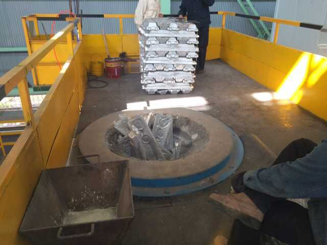
Aluminum melting furnace
Copper melting furnace
Small steel melting furnace
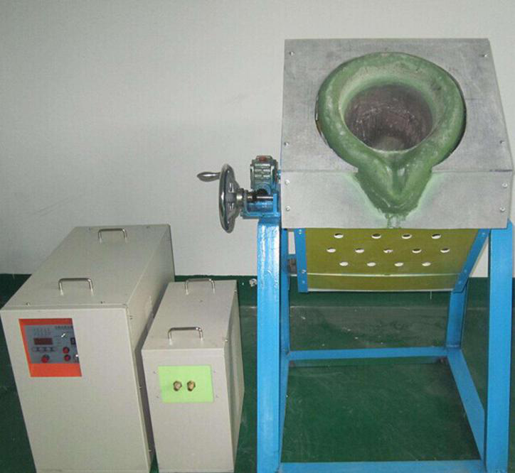
Small induction melting furnace
Induction iron furnace
3T intermediate frequency iron melting f

0.25T Intermediate Frequency Furnace

0.5T Intermediate Frequency Furnace

Medium Frequency Furnace

2T Induction Melting Furnace

1T Induction Melting Furnace

500kg Induction Melting Furnace

250kg Induction Melting Furnace

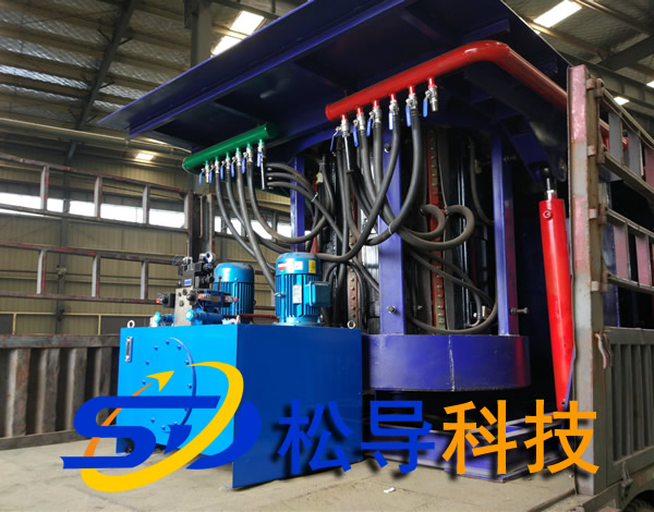
Induction Melting Furnace

3 T Induction Melting Furnace

5T Induction Melting Furnace
1T One Belt Two Intermediate Frequency F

5T One Belt Two Intermediate Frequency F
3T One Belt Two Intermediate Frequency F
2T One Belt Two Intermediate Frequency F
5T Parallel Intermediate Frequency Furna

5T Intermediate Frequency Furnace

5T Series Intermediate Frequency Furnace
3T Series Intermediate Frequency Furnace
2T Series Intermediate Frequency Furnace
1T Series Intermediate Frequency Furnace
0.5T Series Intermediate Frequency Furna

0.25T Series Intermediate Frequency Furn
1T Parallel Intermediate Frequency Furna
2T Parallel Intermediate Frequency Furna
0.5T Parallel Intermediate Frequency Fur