Sales hot line ( 24 hours service): 18037961302
E-Mail: firstfurnace@gmail.com
whatsapp:+8618037961302
Adress: Luoxin Industrial Park, Luoyang, HenanLarge diameter steel pipe quen
Piston rod quenching and tempe
Grinding rod quenching and tem
High frequency induction heate
Quenching equipment for machin
Round steel end heating furnac
Steel pipe heat treatment prod
Square steel quenching and tem
Sucker rod quenching and tempe
Thickened petroleum steel pipe
Round steel quenching and temp
Steel pipe quenching and tempe
Steel plate quenching and temp
Induction Hardening Machine&nb
Flywheel ring gear high freque
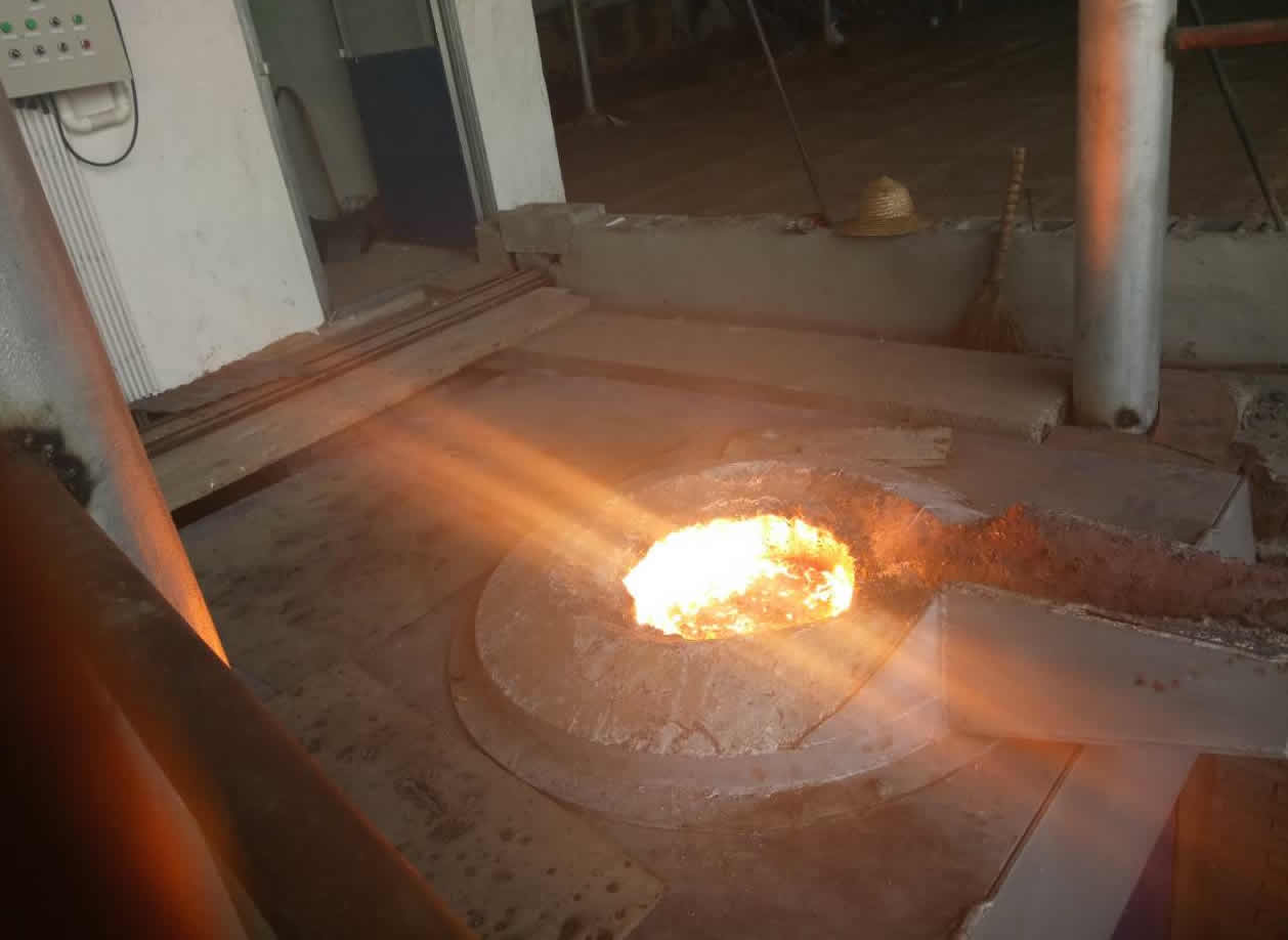
1 Principle of Induction melting furnace
Induction heating is used to heat electrically conductive material. The heat energy is transferred to the material in the induction melting furnace (called the charge) by electromagnetic induction. Refer to Figure 1. An electrically conductive material placed in a varying magnetic field will have eddy currents induced into it. These eddy currents will lead to joule heating (I^2.R heating) in the material. For magnetic materials, e.g. iron and steel, there is also hysteresis heating until the furnace charge reaches the curie temperature (around 750 degC) at which point the material loses its magnetic properties.
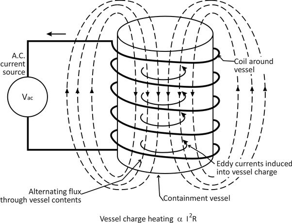
Figure 1: Principle of Induction Heating
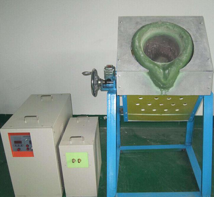
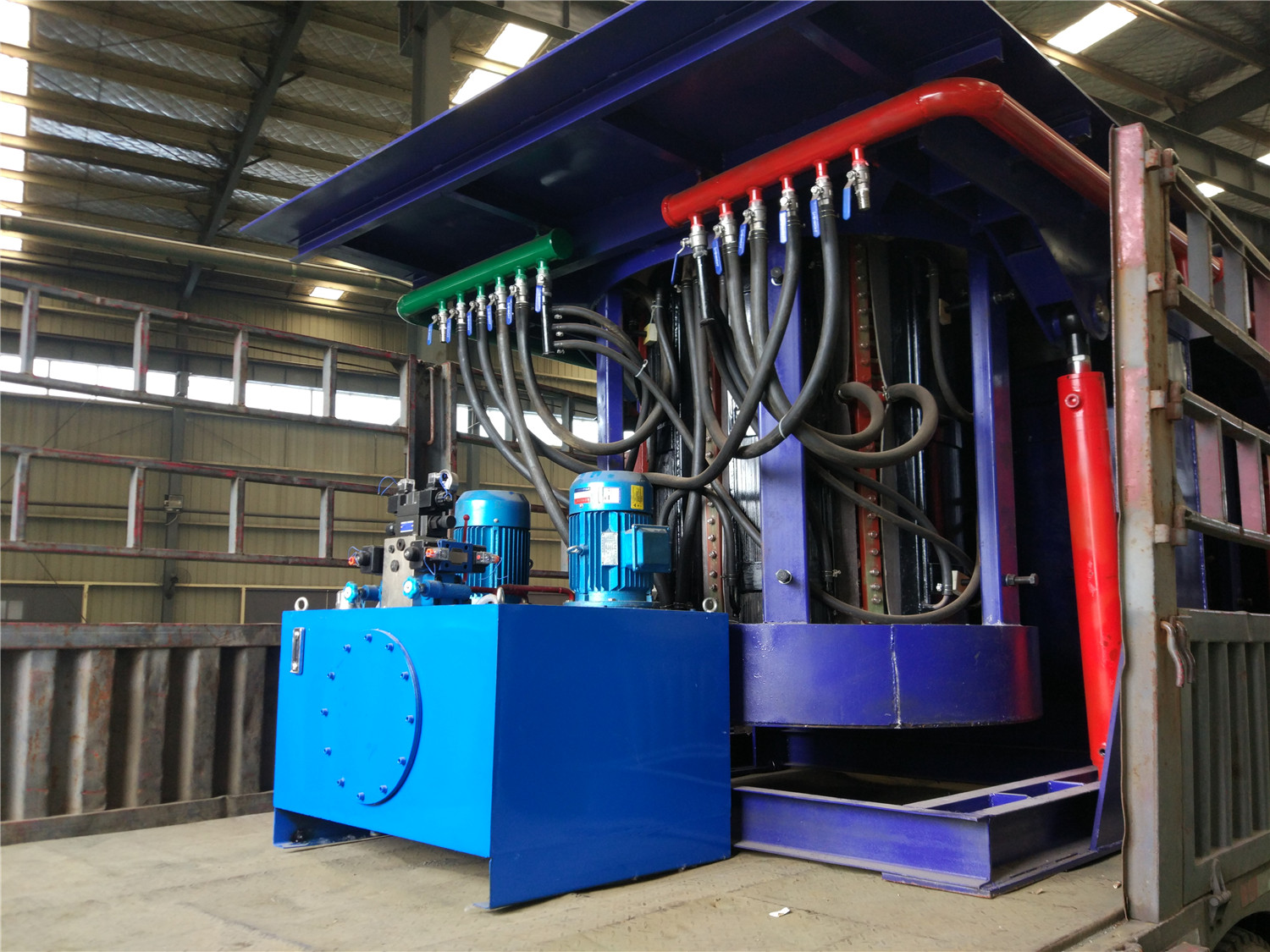
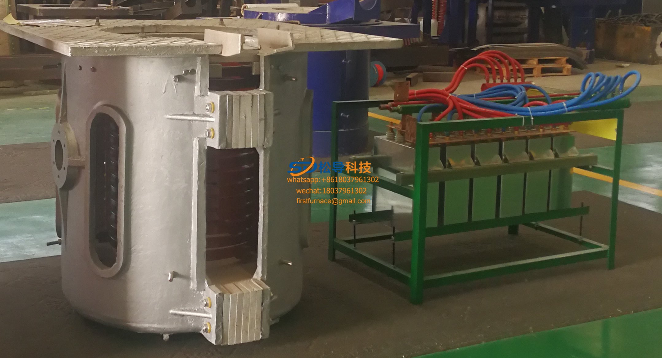
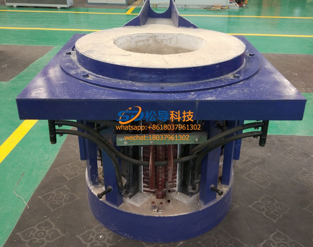
2 Construction of an Induction Furnace
Refer to Figure 2.
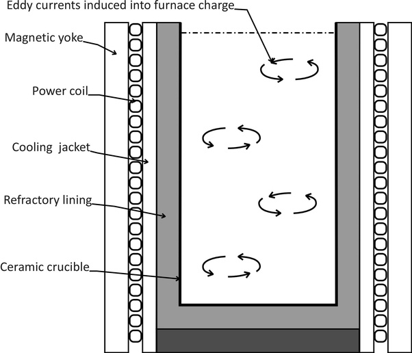
Figure 2: Construction of Induction Heating Furnace
The electromagnetic energy is delivered by the power coil. It is carrying large current and needs to be cooled, from its own I^2.R losses and from the heat generated in the furnace. It is typically hollow copper tube with de-ionised water circulating inside.
The power coil surrounds the ceramic crucible which carries the charge. It is separated by a refractory lining and a cooling water jacket. The crucible and lining must be non-conductive electrically and be able withstand the high charge temperatures - up to 1500 degC for steel.
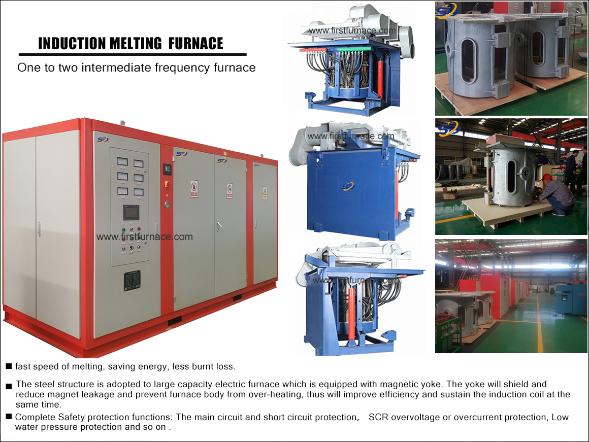
The outside of the coil is lined with a magnetic yoke made from laminated magnetic iron. This provides a low- loss low-reluctance return path for the magnetic flux. For higher frequency furnaces, this lining may be a material with lower hysteresis, such as a soft ferrite.
Benefits of Induction Heating Furnace
�� High melt efficiency �C typically 70% to 85%
�� Good mixing of charge �C the eddy currents help to circulate the charge to spread the heat evenly and mix the charge components..
�� Clean process �C the heat is transferred to the charge by electromagnetic waves. So there is no contact with flame and no product contamination.
�� The furnace is fast to start and heating is rapid.
3 Induction Coil Energisation
The coil is placed in series or parallel with a capacitor to make a resonant circuit. A driver circuit is used to replace the energy lost in each cycle and to maintain oscillation. The resonant frequency will determine the frequency of the magnetic field. The higher the frequency, the higher the eddy currents. However the higher the frequency the less the eddy currents will penetrate the charge because of skin effect. So the best operating frequency is a compromise between these two effects. Smaller furnaces e.g. for precious metal or semiconductor smelting, may run at 3kHz or higher. Larger furnaces for iron and steel production run at 300Hz or less.
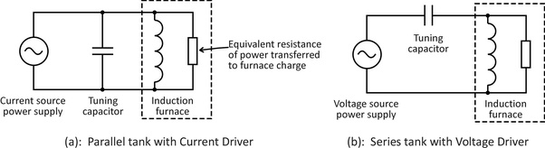
Figure 3: Parallel and Series Resonant Circuits and Drivers
For a parallel tank circuit, as shown in Figure 3(a), the driver power supply is subject to the full voltage across the tank. It supplies bursts of current at the correct time in each cycle to the tank circuit to maintain oscillation. Thus it is known as a current driver.
For a series tank circuit, as shown in Figure 3(b), the driver power supply is subject to the full current circulating in the tank circuit. It supplies correctly timed bursts of voltage to the tank circuit to maintain oscillation, hence is known as a voltage driver.
Typically the tank circuit runs at a Q factor of approximately 10. This means on every cycle the circulating current decays by 10% because of the energy absorbed by the charge, plus other losses. This needs to be made up by the power supply driver circuit. There are two types of driver in use, depending on whether it is a series resonant or parallel resonant circuit.
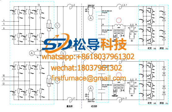
3.1: Current Driver Circuit
4: Current Driver with Parallel Tank Circuit
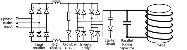
The current driver is shown in more detail in Figure 4. It uses a SCR controlled rectifier followed by an SCR controlled inverter bridge. The circulating current in the tank circuit is controlled by the firing angle of the rectifier SCRs. One diametrically opposite pair of inverter SCRs is fired to inject current into the tank circuit in one direction, and the other pair inject current in the opposite direction. The timing is controlled to sustain oscillation. A small degree of control over tank frequency is achievable by controlling the firing angle of the inverter SCRs.
3.2: Voltage Driver Circuit
Refer to Figure 5. A simple 3-phase diode rectifier is filtered by an electrolytic capacitor to generate a fixed D.C. voltage. This voltage is added to or subtracted from the tank capacitor voltage by a single phase inverter bridge consisting of 4 IGBTs. The inverter switches can be force commutated which means we have full control over the tank current and oscillation frequency.
The maximum voltage to be blocked by the inverter switches is the D.C. link voltage so required voltage ratings are low. However the inverter bridge is carrying the full tank current so the required switching current is high.
3.3 Comparison of Circuits
In general the circuit in Figure 5 (voltage driver) is preferred these days. It has the following benefits over the urrent driver circuit of Figure 4:
�� Higher controllabilty of melt
�� More efficient
�� Less notching and distortion of incoming mains
�� Better mains power factor.
The circuits shown are all for higher power induction furnaces. These may be scaled down for (e.g.) precious metal refining by using a single phase input power supply.
www.tecfurnace.com
www.songdaofurnace.com
Iron induction furnace
Aluminum melting furnace
Copper melting furnace
Small steel melting furnace
Small induction melting furnace
Induction iron furnace
3T intermediate frequency iron melting f

0.25T Intermediate Frequency Furnace

0.5T Intermediate Frequency Furnace

Medium Frequency Furnace

2T Induction Melting Furnace

1T Induction Melting Furnace

500kg Induction Melting Furnace

250kg Induction Melting Furnace

Induction Melting Furnace

3 T Induction Melting Furnace

5T Induction Melting Furnace
1T One Belt Two Intermediate Frequency F

5T One Belt Two Intermediate Frequency F
3T One Belt Two Intermediate Frequency F
2T One Belt Two Intermediate Frequency F
5T Parallel Intermediate Frequency Furna

5T Intermediate Frequency Furnace

5T Series Intermediate Frequency Furnace
3T Series Intermediate Frequency Furnace
2T Series Intermediate Frequency Furnace
1T Series Intermediate Frequency Furnace
0.5T Series Intermediate Frequency Furna

0.25T Series Intermediate Frequency Furn
1T Parallel Intermediate Frequency Furna
2T Parallel Intermediate Frequency Furna
0.5T Parallel Intermediate Frequency Fur