Sales hot line ( 24 hours service): 18037961302
E-Mail: firstfurnace@gmail.com
whatsapp:+8618037961302
Adress: Luoxin Industrial Park, Luoyang, HenanLarge diameter steel pipe quen
Piston rod quenching and tempe
Grinding rod quenching and tem
High frequency induction heate
Quenching equipment for machin
Round steel end heating furnac
Steel pipe heat treatment prod
Square steel quenching and tem
Sucker rod quenching and tempe
Thickened petroleum steel pipe
Round steel quenching and temp
Steel pipe quenching and tempe
Steel plate quenching and temp
Induction Hardening Machine&nb
Flywheel ring gear high freque
Technical parameters and analysis of hydrogen sintering furnace
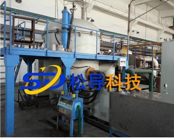
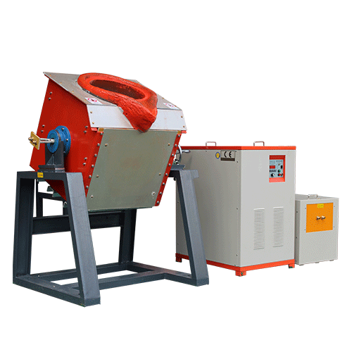
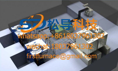
First, equipment overview and use:
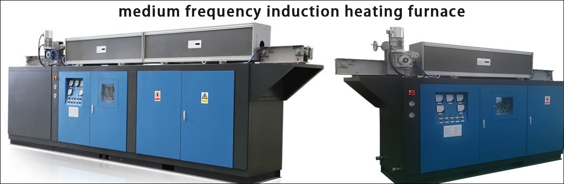
This equipment is suitable for modern equipment for metal heat treatment under the principle of medium frequency induction heating under hydrogen. This product heating is a kind of static and constant frequency conversion device, which converts 50Hz three-phase power frequency electric energy into single-phase intermediate frequency electric energy. This series of equipment applies the principle of electromagnetic induction. Under the protective gas environment, the workpiece is placed in an alternating magnetic field, which generates eddy current loss and generates heat, which meets the requirements of heating such as sintering and heat transfer. This heating method has the advantages of fast heating, less burning loss and low labor intensity, which can ensure product quality.
The main technical parameters:
a) Rated working power supply 3N 380V ±20V, 50Hz±1Hz
b) Rated heating power is about 500kw (the actual heating power is steplessly adjustable)
c) Rated working furnace temperature 2350 ° C (design furnace temperature 2400 ° C)
d) Heating rate ≤ 20 °C / min
e) Instrument temperature control accuracy ≤ ± 2 ° C
f) Temperature measurement method 0-1000 °C thermocouple (automatic delivery) 1000-3000 °C infrared
g) Temperature control mode: manual control and intelligent program control (heating according to a given temperature rise curve)
h) Temperature record: Small long chart recorder records temperature and industrial computer data record
i) Working atmosphere: Hydrogen (hydrogen flow rate is not less than 20m 3 /h, pressure is not less than 0.04MPa.)
j)Protective atmosphere: nitrogen ( pressure not less than 0.04MPa)
k) Effective size in high temperature zone: Ф600×1500
l)Heating element size Ф600×1500 (tungsten)
m)Furnace type vertical
n)Discharge method: lower discharge
o) Inlet and discharge mechanism mode Mechanical type (automatic screw type)
p) Inlet and discharge mechanism speed 0.5-1.2m/min (speed variable frequency adjustment, automatic stop after being in place)
q) Material table access mode Mechanical track type (acceleration and deceleration time adjustable, guarantee stability)
r) Lower cover self-locking method
s)Vacuum pumping speed ≤0.5 hours
t) Empty furnace cold state ultimate vacuum ≤ 10Pa
u) Pressure rise rate ≤0.67 Pa/h
v)Furnace surface temperature rise ≤ 30 ° C
w)Cooling water rated pressure 0.1~0.3M Pa
x)Cooling water flow: approx. 15 m 3 /h
y)Compressed air pressure 0.4-0.6 MPa
z)Medium frequency heating parameters:
IF power frequency 2500HZ
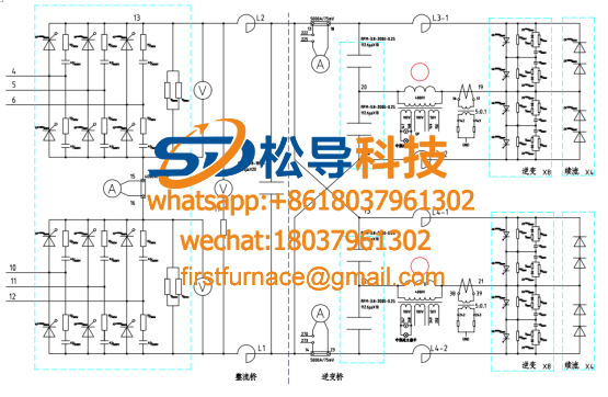
Rectification mode: three-phase full control bridge rectification
Rated DC voltage: 510V
DC Current Rating: 600A
Rated output voltage: 750V-800V
Rated power: 300KW
Efficiency: ≥92%
Control method: digital integrated circuit control.
Trigger pulse: double narrow column pulse.
Protection method:
Overcurrent, overvoltage rectification pull inverter protection;
Shutoff, power blocking protection
Relay protection; RC, LC absorption protection
Fast fuse protection
Furnace temperature over temperature, overshoot protection, temperature sensor fault protection
System under water, water shortage, water temperature over temperature and water pressure ultra high protection
Protective gas underflow protection
Power adjustment mode:
Manual mode
PID adjustment, automatic working mode along the specified heating curve (user specified).
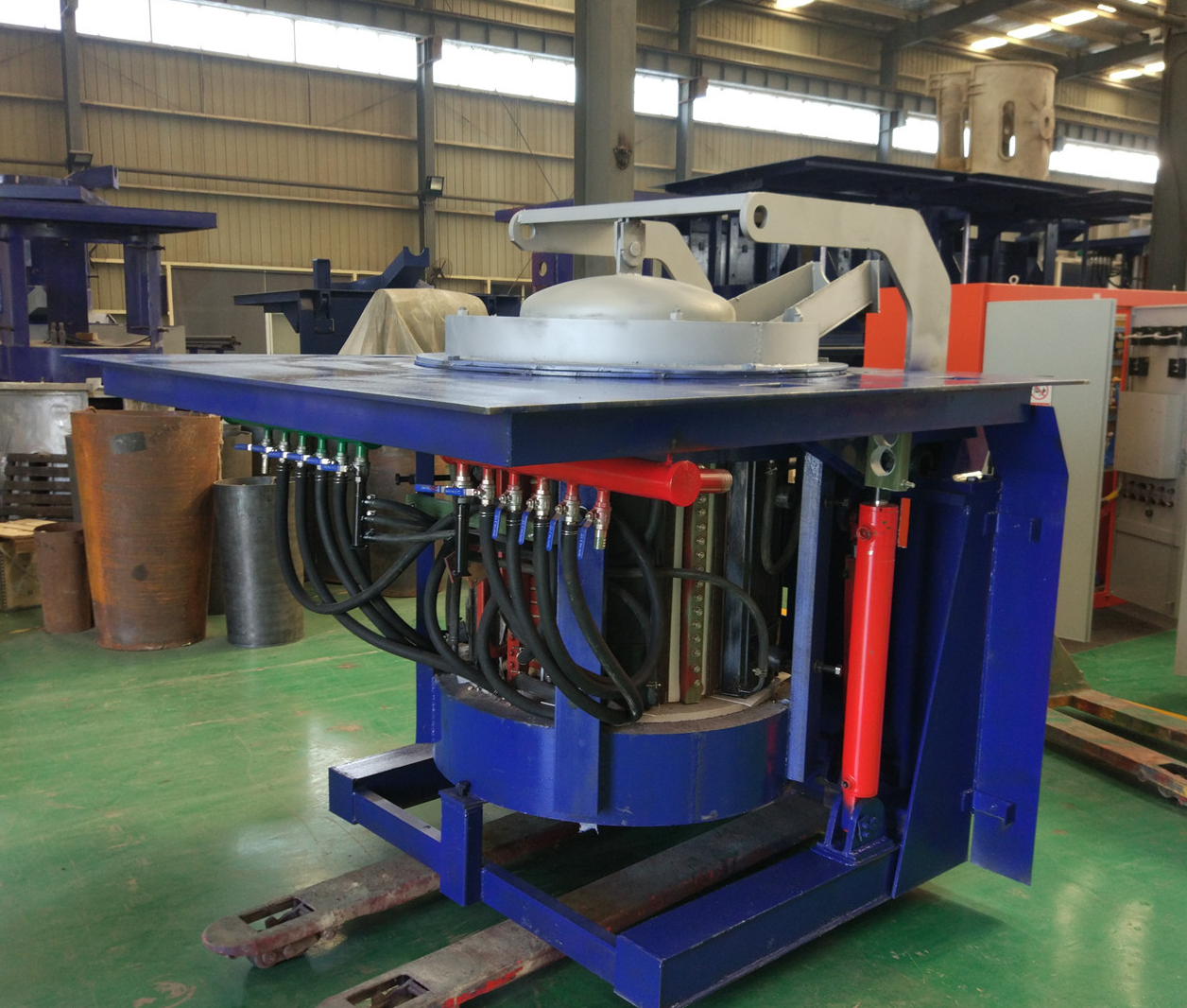
Fifth, the principle, structure and characteristics
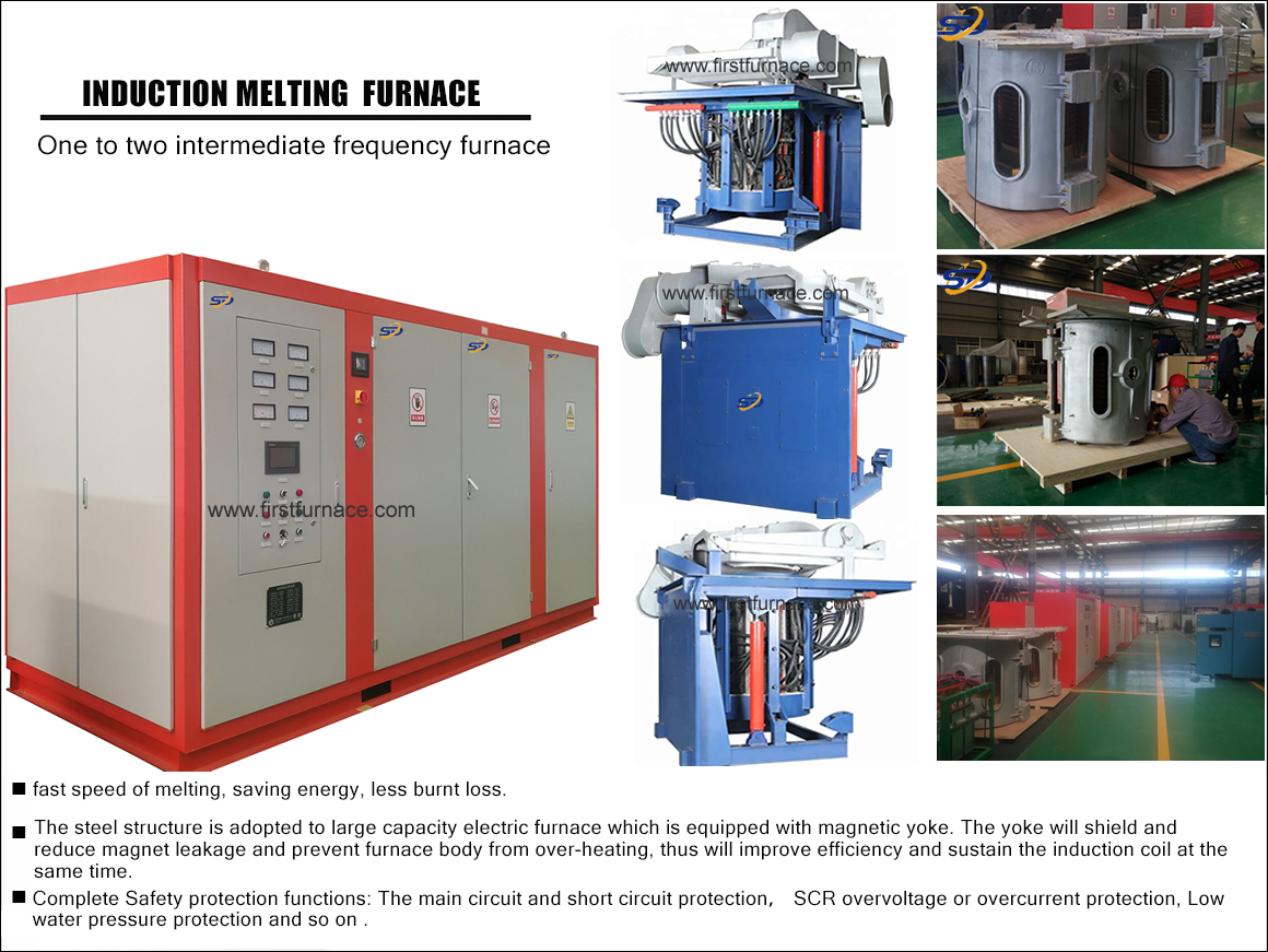
The equipment consists of a furnace body, a vacuum obtaining system, an electric control system, a vacuum control system, an intermediate frequency heating system, an aeration system, and a water cooling system. The device is a heat treatment device using medium frequency induction heating. The inside of the furnace body is provided with a spiral tube coil. When the coil is connected with an intermediate frequency current, an alternating magnetic field is generated. The metal charge induces an electric potential under the action of a magnetic field to generate a toroidal current. This current concentrates on the outer layer of the metal charge under the action of its own magnetic field, so that the outer metal charge has a high current density, thereby generating a concentrated and powerful The thermal effect has caused the metal to be heated to produce a high temperature of up to 2400 ° C in the furnace.
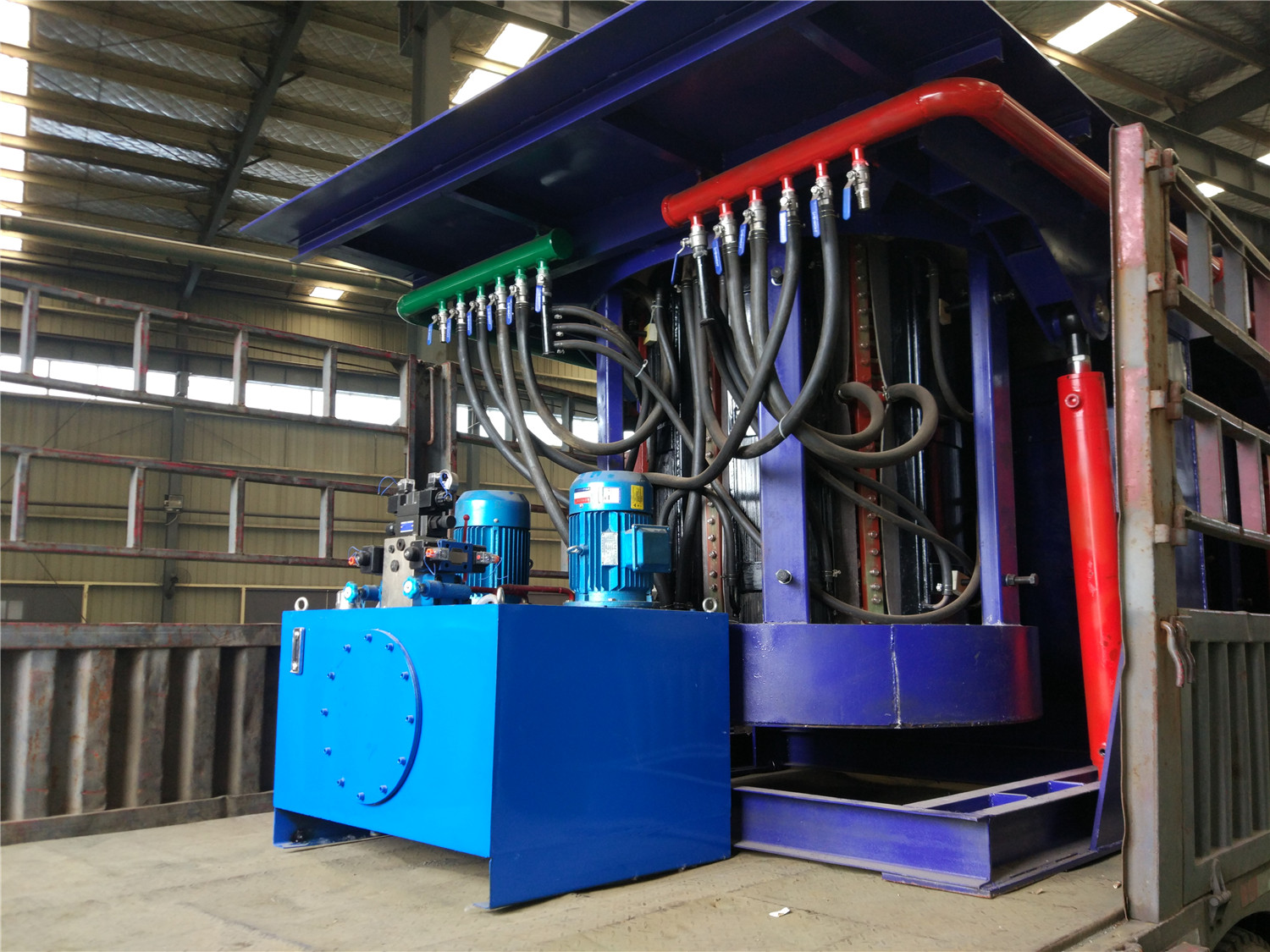
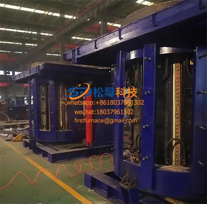
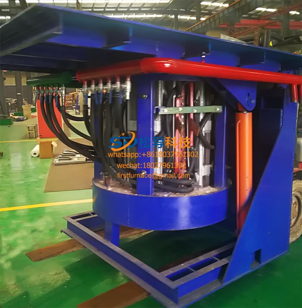
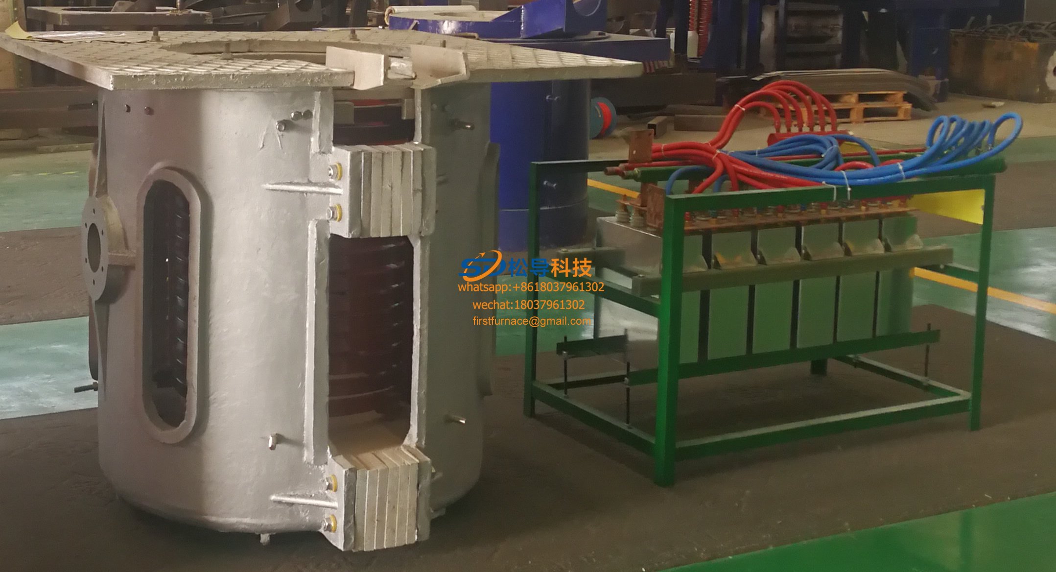
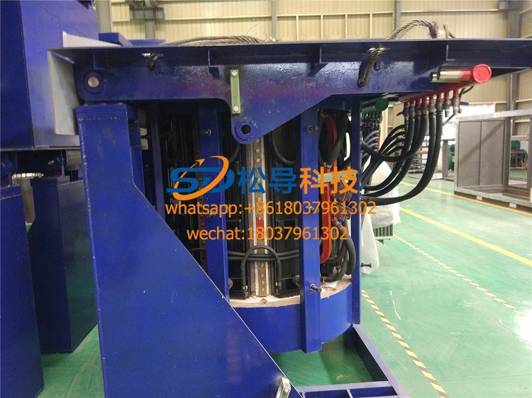
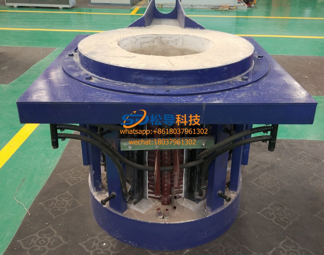
5.1 furnace body
The furnace body is a vertical single-chamber water-cooled jacket structure, and the furnace door is a double door structure. The sandwich water jacket is used, the inner layer material is stainless steel SUS304/δ=10mm, the outer layer material is stainless steel SUS304/δ=8mm, and the flange material at both ends is stainless steel plate SUS304/δ=35mm. The surface of the furnace body is uniformly polished to improve the vacuum of the equipment. The furnace body is provided with observation holes, air inlets, vacuum, combustion ports, explosion-proof holes, electrical interfaces, and the like. All interfaces are vacuum O-ring flange connection, and the vacuum chamber leakage is very low.
The vacuum chamber is composed of an induction coil, a high temperature insulation layer, a high temperature heat insulation screen, a high-purity crucible, and the like from the outside to the inside. The indoor wall of the vacuum has movable pedals for easy installation and discharge.
The insulation material is made of alumina brick, the temperature is above 1800 degrees, the material density is about 5.0g/cm 3 , and the thickness is about 60mm.
The high temperature insulation layer is made of zirconia heavy brick, with a temperature resistance of more than 2400 degrees, a material density of about 2.0 g/cm 3 , a purity of ZrO 2 ≥99%, and a thickness of about 40 mm.
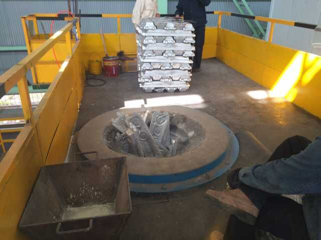
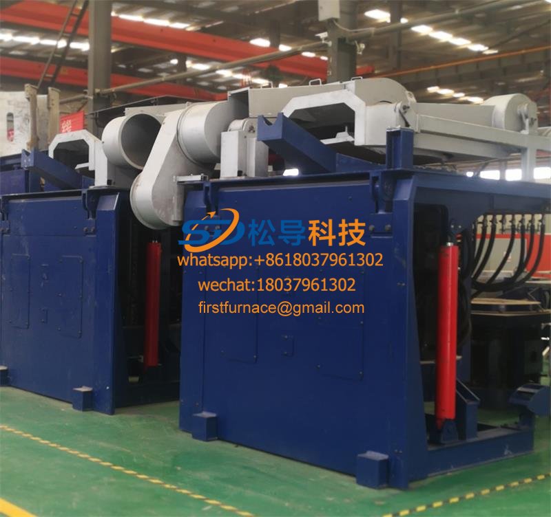
The upper furnace cover is an open structure. When the furnace cover is opened, the furnace cover self-locking device is released, the electric reducer drives the furnace cover to rise, and then the furnace cover is manually rotated. Then load and unload the material from the upper furnace mouth.
The lower furnace cover is a lower opening structure. When the furnace cover is opened, the hydraulic automatic locking device is released, and the frequency converter drives the variable frequency motor to drive the ball screw to move downward. After the position, the screw locking device is released, and the trolley drives the lower furnace cover together to send out the material along the track.
The furnace body design workbench, the steel structure work platform surrounds the furnace body, and the platform has convenient stairs and protective guardrails.
5.2 vacuum acquisition system
The vacuum unit system consists of two vacuum systems consisting of an H-150 vacuum pump and a ZJP-300 Roots pump. The main valves on each pipeline of the vacuum system of the furnace adopt manual vacuum butterfly valve + automatic flapper valve, which is intuitive and convenient to operate. The manual valve can be operated manually in the emergency state. The automatic valve is executed when the automatic program is running, which can reduce the operation error as much as possible. The digital vacuum gauge and the metal vacuum gauge are used to make the vacuum more accurate. The use of a two-stage vacuum pump allows the vacuum chamber to quickly reach an ultimate vacuum of 10 Pa or less in 30 minutes.
5.3 Electrical Control System
The device adopts a touch screen, and the main panel displays the working state in the furnace in an all-round manner, the operating state of each control point, and the dynamic mode demonstrates the heating condition in the furnace. Record all kinds of important data comprehensively and archive them in real time to match them. Ability to record temperature, incoming voltage, DC voltage, intermediate frequency voltage, power, single furnace power consumption, hydrogen source pressure, furnace gas pressure, vacuum, cooling water pressure, cooling water outlet temperature (inductor), hydrogen dew point, etc. . All display data is retrieved by converting the data to strong conversion. And the industrial touch screen has manual control buttons for all control points.
Equipped with a paper recorder, it can realize the paper recording of heating data to ensure the authenticity of the data.
The equipment is equipped with advanced intelligent temperature measurement and temperature control devices to measure and control the temperature of the furnace high temperature zone to ensure product quality and furnace safety.The instrument adopts Japan Island Electric FP23, and the temperature measuring device adopts American Leitai (MR1SCSF). The heating process (heating and heat preservation process) can be completed automatically by the program. The operator only needs to adjust the stored heating process curve before starting the machine. Run, the system will display and record the current temperature status of the heating process in all directions.
The system is equipped with a full range of water, electricity and gas protection and alarm devices with PLC as the core, ensuring that the equipment can be turned on only under the conditions of all aspects. Such as furnace temperature over-temperature overshoot, cooling water owing water, cooling water temperature, sensor failure, insufficient shielding gas flow, over current, over voltage, three-phase incoming line phase loss, undervoltage, overpressure, etc., immediately sound and light Alarm, stop heating, remind the operator to deal with the scene in time to ensure system safety.
The vacuum system is measured and controlled using a digital vacuum gauge. It also has the automatic control function of the vacuum unit interlock to ensure reliable starting under the vacuum required by each vacuum pump.
The IF power supply can be configured for automatic-manual conversion; remote-to-machine control conversion settings are available.
5.4 intermediate frequency heating system
The starting performance is good : the device adopts the “zero pressure” starting mode, the starting current is from small to large, and rises smoothly, without any impact on the power grid and other electrical equipment.
Strong protection : The device has over-current protection, over-voltage protection, thyristor positive and negative transient over-voltage resistance-capacitance absorption protection, fast-fuse protection, shut-off and cut-off protection, cooling water pressure under-protection, phase loss protection, etc. Kind of protection.
Main control board : The rectification trigger part is controlled by AC63S programmable device , with high reliability, good pulse symmetry, strong anti-interference ability and fast response speed. The inverter adopts the sweeping zero-voltage starting mode, and the starting performance is better than the ordinary zero-voltage soft starting circuit. It has an automatic repeating start function. It can prevent the occasional startup failure of the intermediate frequency power supply and make the startup success rate reach 100%.
The IF power supply uses automatic frequency tracking control, so the IF power supply can be automatically tracked regardless of the frequency of the load, without any manual adjustment. When used in different frequency bands, since the impedance of the load will change, just connect the corresponding compensation capacitor bank to adjust to the appropriate impedance value.
The IF power cabinet panel is equipped with a pointer table: intermediate frequency voltage, incoming line voltage, DC voltage, DC current, power meter, etc. MF manual operation button, manual power regulator, manual self-conversion button, local/remote power control conversion button, etc.
The induction coil is the heart of the whole induction furnace. The induction coil is powered by the intermediate frequency power supply. Under the action of the intermediate frequency voltage and current, a strong magnetic field is generated. This magnetic field causes the metal in the furnace to generate eddy current and heat. The coil is the key to the thermal energy conversion. Therefore, the coil design is very important. The coil of the electric furnace is a better solution determined by the computer analysis and calculation according to the electromagnetic field principle in combination with the actual use condition of the intermediate frequency furnace at home and abroad.Usually, the inside of the induction coil and the gap between the turns are coated with refractory mortar with good insulation performance, which can conveniently carry out the lining of the lining and prevent the lining life from being affected by the cold and hot deformation of the lining.
The induction coil is made of a mica tape and a immersion varnish. The exterior is coated with a layer of gray insulating varnish. The insulation layer has a withstand voltage greater than 2000V. The induction coil is made up of a series of bolts welded to the outer circumference thereof, and is fixed by a stainless steel shaped member and a magnetic insulator. After the coil is fixed, the pitch error of the coil is not more than 2 mm. The induction coil is designed to take into account the influence of the inherent length of the copper tube. The welding and the water guiding part of the copper tube are combined, so that each group of induction coils is wound with the entire copper tube and no weld seam is needed inside. The junction of the induction coil electrode and the furnace body is connected by an insulating flange to ensure the airtightness of the furnace body, and the connection with the capacitor cabinet is connected by a water-passing copper pipe. And the busbar has safety guards. At the water outlet of the induction coil, several water temperature probes are installed according to the water path. When the water temperature of a certain road is blocked, the alarm can be immediately issued, and the intermediate frequency power supply can be automatically stopped.
The copper tube of the inductor is made of T2 high-quality copper material with a thickness of more than 3mm. After the sensor is completed, the pressure measurement method is applied at 0.8MPa in the factory, and the pressure is leak-proof for 24 hours to ensure no leakage during operation. The temperature of the cold water of the sensor design is ≤15 °C.
Since the power factor of the induction coil is very low, the intermediate frequency capacitor is required to perform reactive compensation on the coil. Compensation power 3000kvar
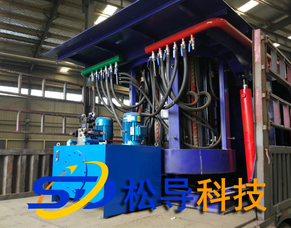
5.5 Inlet and outlet water cooling system
It adopts the form of busbars; after the total advancement, the water supply valve is supplied with multiple points; the effluent is converged by multiple points; the water entering each point is marked, and the water pressure of the total inlet is measured.
The sensor outlet has temperature display and temperature alarm (and can control the temperature of the inlet and outlet water through the digital temperature controller to control the temperature of the inlet and outlet water, so that the closed cooling tower can continuously and efficiently operate the equipment within the specified water temperature range. Cooling)
The cooling waterway design ensures that the water flow diversion has no dead angle, no air resistance, and the water outlet is at the highest point.
The main circuit high-power thyristor device, electric heating capacitor, induction heater, reactor, etc. are water-cooled.
Equipment cooling water allows water cut time: In principle, the equipment is not allowed to break water during operation. Especially at high temperature, the sensor is absolutely not allowed to cut off water. The longest water cut time is about 5 minutes.
The equipment has a water transfer interface (can be designed to automatically convert)
The equipment can be equipped with a closed water cooling tower, which can save the pool and reduce the space occupied by the equipment.
5.6 Inflatable pneumatic system
Nitrogen and hydrogen gas are sent out from the gas cylinder, and after passing through the flow meter equipped with the equipment, the pressure gauge enters the furnace body through the electromagnetic inflation valve. The hydrogen inlet and outlet are equipped with high and low pressure alarm devices. Hydrogen inlet side equipment is designed to detect dew point temperature to effectively detect hydrogen pressure.
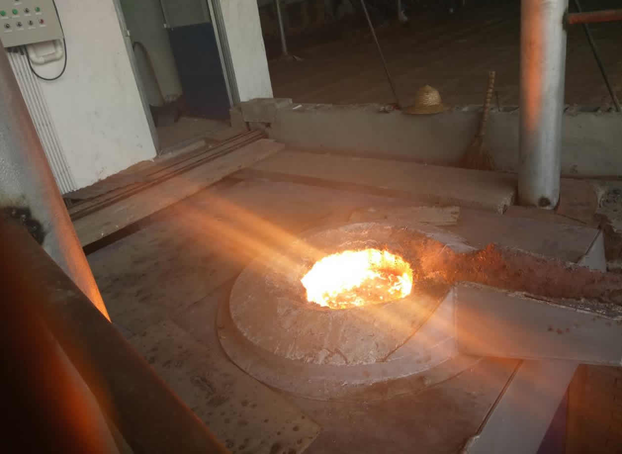
After the hydrogen gas passes through the furnace hall, the exhaust port is taken out at the lower part of the furnace body, and a water seal is arranged at the exhaust port to the combustion port, so that the gas bubble size and the flow velocity can be visually seen.
The tail gas treatment method is manual blasting and ignition.
The equipment is designed with an emergency switching device for the hydrogen/nitrogen supply system, which is automatically switched by a pneumatic solenoid valve.
Sixth , the main equipment components
|
Serial number |
Device name |
Specification model |
Quantity |
Remarks |
|
1 |
KGPS IF power supply |
KGPS-500KW/2500Hz |
1 set |
|
|
2 |
capacitor bank |
4000kavr |
1 set |
|
|
3 |
Furnace body |
|
1 set |
|
|
4 |
Upper lid lifting mechanism |
|
1 set |
|
|
5 |
Lower lid lifting mechanism |
|
1 set |
|
|
6 |
Lower cover self-locking mechanism |
|
1 set |
|
|
7 |
Lower cover removal mechanism |
|
1 set |
|
|
8 |
sensor |
|
1 set |
|
|
9 |
Water cooled electrode |
500KW |
1 set |
|
|
10 |
Output cable |
Power to capacitor |
1 set |
|
|
11 |
Insulation |
|
1 set |
|
|
12 |
heat insulation |
|
1 set |
|
|
13 |
Tungsten |
|
1 set |
|
|
14 |
Vacuum pump unit |
|
1 set |
|
|
15 |
Inflatable system |
|
1 set |
|
|
16 |
Industrial control system |
|
1 set |
|
|
17 |
Cooling system |
|
1 set |
|
|
18 |
Water cooling unit |
Optional |
1 set |
|
|
19 |
platform |
|
1 set |
|
|
20 |
|
|
|
|
Iron induction furnace
Aluminum melting furnace
Copper melting furnace
Small steel melting furnace
Small induction melting furnace
Induction iron furnace
3T intermediate frequency iron melting f

0.25T Intermediate Frequency Furnace

0.5T Intermediate Frequency Furnace

Medium Frequency Furnace

2T Induction Melting Furnace

1T Induction Melting Furnace

500kg Induction Melting Furnace

250kg Induction Melting Furnace

Induction Melting Furnace

3 T Induction Melting Furnace

5T Induction Melting Furnace
1T One Belt Two Intermediate Frequency F

5T One Belt Two Intermediate Frequency F
3T One Belt Two Intermediate Frequency F
2T One Belt Two Intermediate Frequency F
5T Parallel Intermediate Frequency Furna

5T Intermediate Frequency Furnace

5T Series Intermediate Frequency Furnace
3T Series Intermediate Frequency Furnace
2T Series Intermediate Frequency Furnace
1T Series Intermediate Frequency Furnace
0.5T Series Intermediate Frequency Furna

0.25T Series Intermediate Frequency Furn
1T Parallel Intermediate Frequency Furna
2T Parallel Intermediate Frequency Furna
0.5T Parallel Intermediate Frequency Fur