Sales hot line ( 24 hours service): 18037961302
E-Mail: firstfurnace@gmail.com
whatsapp:+8618037961302
Adress: Luoxin Industrial Park, Luoyang, HenanLarge AC Motors Terminal Rings
Medium-frequency welding of mo
Medium-Frequency Brazing Equip
Integral Brazing Process for t
Online Heating Equipment for T
Online Heating Equipment for A
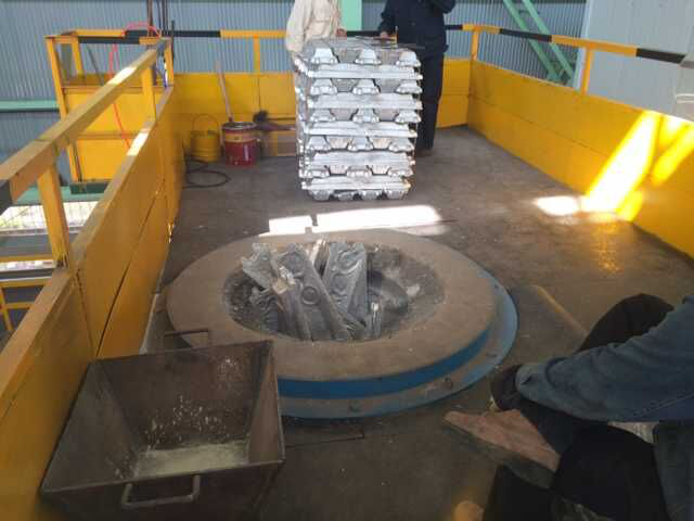
Aluminum ingot heating equipme
Welding Equipment for Traction
Fully Digital Medium Frequency
Motor rotor end ring brazing e
Brazing equipment for hydro ge
Generator rod induction brazin
Hydropower generator stator ba
Large diameter steel pipe quen
Piston rod quenching and tempe
Grinding rod quenching and tem
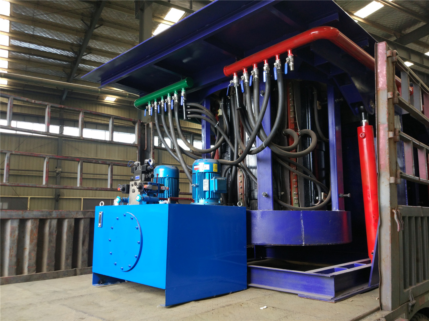
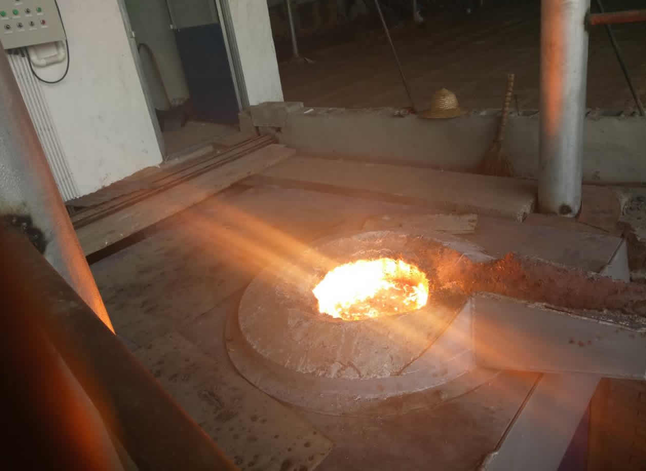
1T inverter series inverter furnace described the principles of the molten steel
The power supply consists of a three-phase bridge rectifier bridge and a thyristor half-bridge inverter circuit. During operation, the rectifier bridge is fully conductive and fully voltage-operated.The main circuit of the inverter consists of two sets of thyristor bridge arms and two sets of resonant capacitors and electric furnace coils. The half-bridge inverter circuit is suitable for high-power low-frequency constant-voltage source inverters.
The two SCRs on the inverter bridge arm are alternately turned on. Any SCR conduction must be triggered after the inverter series load current crosses zero, that is, after the SCR off time TOT, as shown in Figure 5 and Figure 6. The transformer load waveform diagram, when the SCR current crosses zero, the reverse diode connected in parallel with it, its reverse voltage drop turns off the SCR, and then the other arm SCR can trigger conduction. The output frequency of the inverter is 300. -400Hz,
The higher the operating frequency, the greater the output power.
Figure 5 shows the trigger pulse and load waveform of the inverter. The thyristor is regarded as an ideal switch. It is turned on and off instantaneously. The inductor L and the resistor R are connected in series , which is equivalent to the load of the furnace. The trigger pulse frequency is slightly. Below the load resonance frequency f.  Description of the operating current flow path of the half-bridge inverter In the inverter operation, the current passes through the path of the inverter and the furnace coil L. The operating waveform of the inverter is shown in Fig. 7. The constant DC voltage Ud before the inverter operation The capacitors C1 and C2 are equally divided, and each is charged to 1/2 Ud, which is the upper positive and negative voltage. When t=to, SCR1 is triggered to conduct, and the capacitance of the capacitor C1 is discharged through the lower end of SCRl-Lf-Rf-C1. Is to charge C2, +Ud from the upper end of the CF -SCRl-Lf-Rf-C2-CF lower end, these two paths are part of the same resonant circuit, because C1 = C2, so the two channels work at the same frequency, equal to C =C1+C2, the resonant frequency composed of Lf-Rf. When t=t1, C1 discharge ends, C1 voltage is zero, and the voltage on C2 must be charged to Ud. Because the voltage across CF is constant, its value is equal to the sum of C1 and C2 voltages. At this time, the current flowing through the load coil is the maximum. I=I1+I2, due to the magnetic field energy saved in the coil of the furnace body, continue to maintain the above two current flows, so that the capacitor C1 is reversely charged, and the positive and negative are negative, and C2 continues to rise from the Ud value until When t=t2, the magnetic field energy drops to zero.
The coil Lf current I=0, at which time the back pressure on C1 and the forward voltage on C2 reach a maximum value, and the current flowing through the coil of the furnace body is half a sine wave period.

Figure 6 inverter current flow diagram
 Figure 7 Half-bridge inverter operating waveform
Then live under C1, C2 capacitor voltage, the two paths and the two paths are basically the same, except that DI replaces SCR1 through the current, and the current direction is completely opposite to the front, and the current still changes according to the sine wave law until t=t4 When C1 is positively charged to 1/2 Ud, the C2 voltage is also restored to 1/2 Ud, and the furnace coil current is again reduced to zero. Thus, a sine wave period is completed by the current loaded by the furnace body, and when the discharge current passes through the diode D1, The reverse voltage drop causes SCR1 to be turned off. If it is greater than the thyristor SCR1 TOT turn-off time, the SCR2 is triggered to turn on, and the current 14 passes through the lower end of C1-Rf-Lf-SCR2-CF to charge C1, and the furnace coil The electric energy drawn from the power source has the same current and discharge current direction. The closer the time of triggering SCR1 is to the TOT, the greater the power output from the furnace coil. If the SCR2 is not able to pass, the above discharge current will form a negative current of the furnace inductor. Half a cycle, when the current reaches zero, the voltages on C1 and C2 will be equal, equal to 1/2 Ud.
During the conduction of SCR1 or SCR2, the load draws power from the power supply. During the conduction of D1 and D2, the power in the capacitor is fed back to the power supply. Obviously, D1 is turned on during the SCR1 current zero crossing to the SCR2 conduction period. The D1 on-time must be greater than the off-time TOT of SCRl. After SCR2 is turned on, SCR2 will take the current in D1, so that D1 will turn off by itself. The working process of D2 is the same as D1, but it is used to turn off SCR2. .
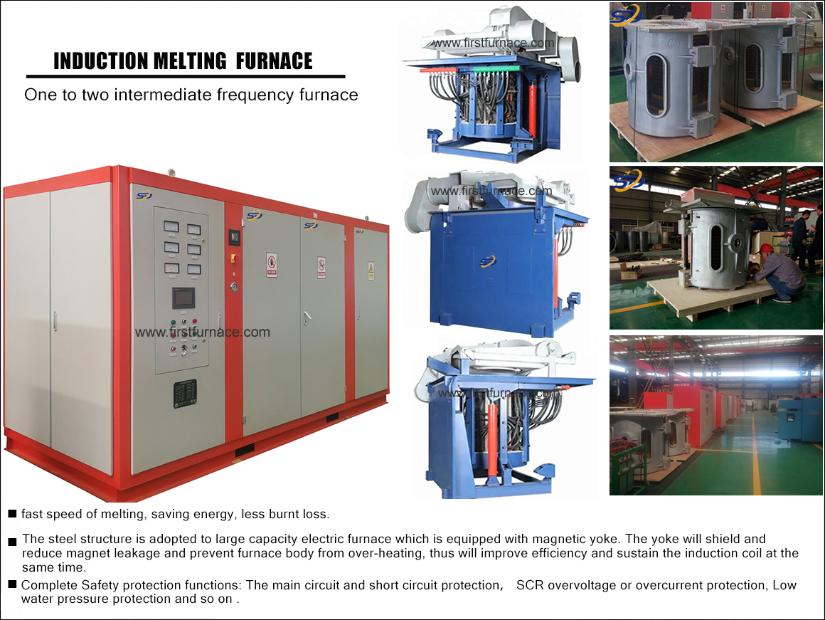
1. 1 T series inverter circuit efficiency of the furnace using molten steel furnace inverter is much higher than the series resonant circuit is parallel inverter furnace, having one with two functions, one power supply may be simultaneously assigned to two electric power, arbitrary power demand , efficient, fast, and energy saving.
2. The control system circuit board and various sensors are installed in the shielding room, and are isolated from the high-voltage high-current copper bus and power devices to avoid strong electromagnetic field interference. The circuit board works in a closed and clean environment, which improves the service life of the circuit board. Stable and reliable, the furnace is easy to operate, and the success rate of the furnace is 100% under any load conditions, including full furnace charge.
3. The rectifier bridge adopts thyristor, which is used as an electronic switch to realize soft start and inverter fault. It can cut off DC power supply quickly. When the electric furnace is running, it does not need to regulate voltage, but operates in full open state, thus has high power supply factor. Therefore, the power supply capacity is reduced, and the interference of the full-pass state operation to the power supply network is minimized.
1T inverter series melting furnace advantages: 1T inverter series inverter steel furnace rectification is divided into single rectification power supply (6-pulse intermediate frequency power supply), dual rectification power supply (12-pulse intermediate frequency power supply) for inverter series inverter operation. It is a technology for inverter series inverter thyristor intermediate frequency power supply, and the inverter resonance circuit is inverter series resonance. The thyristor full-controlled rectifier circuit is adopted, and the intermediate frequency electric furnace adopts the inverter series resonance voltage feedback type control mode, and the output power is controlled by adjusting the trigger frequency of the inverter, and the conduction angle of the rectifying thyristor is not required to be adjusted. To adjust the power, the rectifier thyristor is always in the fully open state, so the power factor is always greater than 0.95, the harmonic content is small, the rectified output voltage is constant, and the waveform is good, so the operation efficiency of the device is high, which can save 10-20%. Electrical energy, energy saving effect is obvious. It can fully meet the national electricity standard requirements of GB/T14549-93. The rectification adopts the 12-pulse thyristor intermediate frequency power supply, and does not contain the 5th and 7th harmonic components. According to the harmonic analysis, the harmonic influence generated by the 12-pulse rectified power supply is much smaller than the 6-pulse ordinary KGPS intermediate frequency power supply. The control system is fully digital and the startup success rate is 100%.
The 1 T inverter series melting furnace operates with an integrated structure, which occupies less space and can reduce the capacity of the high-voltage transformer by half, greatly reducing the investment in the transformer room. All electrical components and matching capacitors are housed in the cabinet to form an integrated power supply for easy installation.

Figure 1 1 Reliable high voltage safety isolation measures
6. With safety protection measures, the electric furnace resonant circuit voltage is very high, the resonant capacitor and the furnace coil voltage can be
Up to 2500V, because the power supply uses a special high-voltage transformer, the winding is △ / Y, the secondary Y midpoint is not connected
Ground (floating), so that the oscillating element and the high-voltage circuit copper row have no relative high-voltage potential to the ground, to the operator
ensure safety.


Large AC Motors Terminal Rings Medium-fr

Electric Motor Rotor Bars and End Rings

Medium-frequency welding of motor rotors

Medium-Frequency Brazing Equipment

Integral Brazing Process for the Rotor E

Online Heating Equipment for Trapezoidal

Online Heating Equipment for Aluminum In

Aluminum ingot heating equipment

Welding Equipment for Traction Motor Rot

Fully Digital Medium Frequency Welding E

Motor rotor end ring brazing equipment

Motor Rotor Guide Bar Welding Heating Eq

Brazing equipment for hydro generator co

Generator rod induction brazing equipmen

Hydropower generator stator bar brazing
Iron induction furnace
Aluminum melting furnace
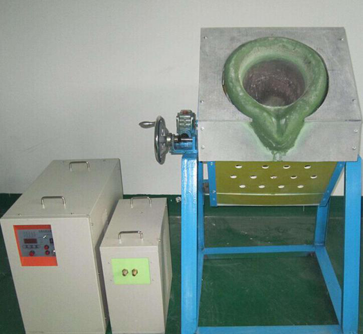
Copper melting furnace
Small steel melting furnace
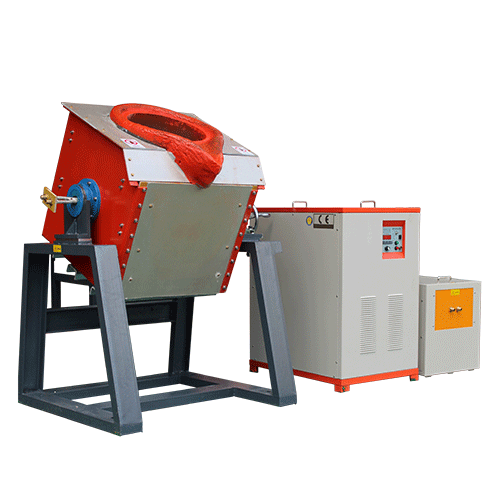
Small induction melting furnace
Induction iron furnace
3T intermediate frequency iron melting f

0.25T Intermediate Frequency Furnace

0.5T Intermediate Frequency Furnace

Medium Frequency Furnace

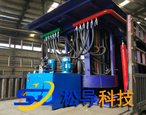
2T Induction Melting Furnace

1T Induction Melting Furnace

500kg Induction Melting Furnace

250kg Induction Melting Furnace

Induction Melting Furnace

3 T Induction Melting Furnace

5T Induction Melting Furnace