Sales hot line ( 24 hours service): 18037961302
E-Mail: firstfurnace@gmail.com
whatsapp:+8618037961302
Adress: Luoxin Industrial Park, Luoyang, HenanLarge diameter steel pipe quen
Piston rod quenching and tempe
Grinding rod quenching and tem
High frequency induction heate
Quenching equipment for machin
Round steel end heating furnac
Steel pipe heat treatment prod
Square steel quenching and tem
Sucker rod quenching and tempe
Thickened petroleum steel pipe
Round steel quenching and temp
Steel pipe quenching and tempe
Steel plate quenching and temp
Induction Hardening Machine&nb
Flywheel ring gear high freque
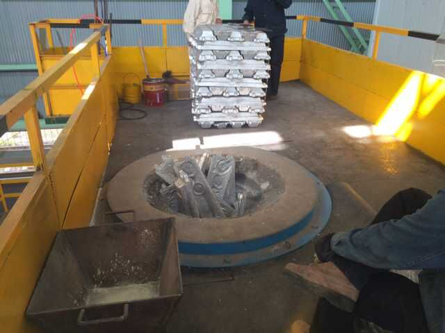
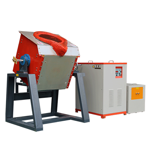
1 ton molten iron water furnace technical parameters and configuration instructions
First, the composition of a single set of equipment:
1. IF rectifier cabinet ( including rectifier filter capacitor)
2, the inverter cabinet ( series resonance with inverter compensation capacitor ) two
3. Melting furnace body ( 3 tons steel shell)
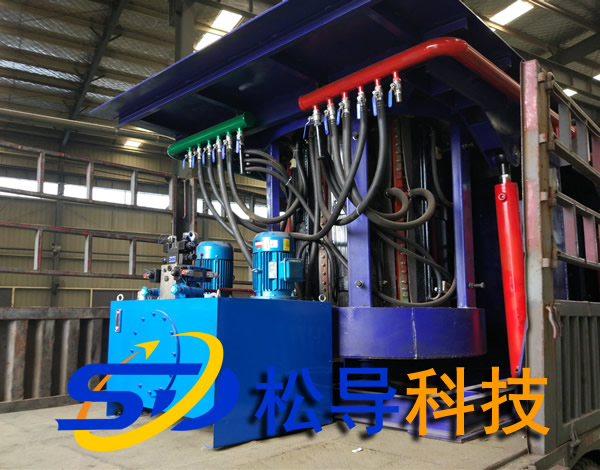
4, hydraulic system
5, the front of the furnace, one
6. Connecting copper bars between the rectifier cabinet and the inverter cabinet
7, water-cooled cable four
8, model one
9, water dispenser
10, leaking furnace alarm device
11. The water connection part between the power supply and the furnace body
1 2 , a set of lining fast ejection mechanism
Power supply parameters
|
Serial number |
project |
parameter |
unit |
Remarks |
|
1 |
Power rating |
2000 + 5 00 |
Kw |
Both smelting and insulation |
|
2 |
Power unidirectional maximum power |
20 00 |
Kw |
Single power supply |
|
3 |
Power input voltage |
950 |
V |
|
|
4 |
Rectifier form |
12 pulse wave |
|
|
|
5 |
Grid side power factor |
>0.9 6 |
|
In any power situation |
|
6 |
Inverter form |
SCR series |
|
Dual power supply |
|
7 |
Inverter output frequency |
400 |
Hz |
|
|
8 |
Start success rate |
100% |
|
in any circumstances |
|
9 |
Power conversion efficiency |
0.97 |
|
|
|
10 |
Power consumption |
5 0 0 ±5% |
Kwh/t |
Melted from hot normal temperature to 1450 ° C |
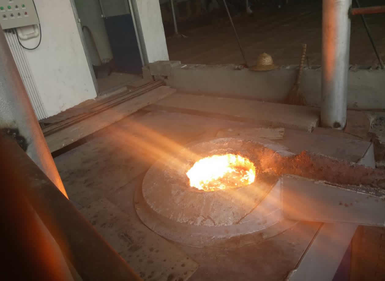
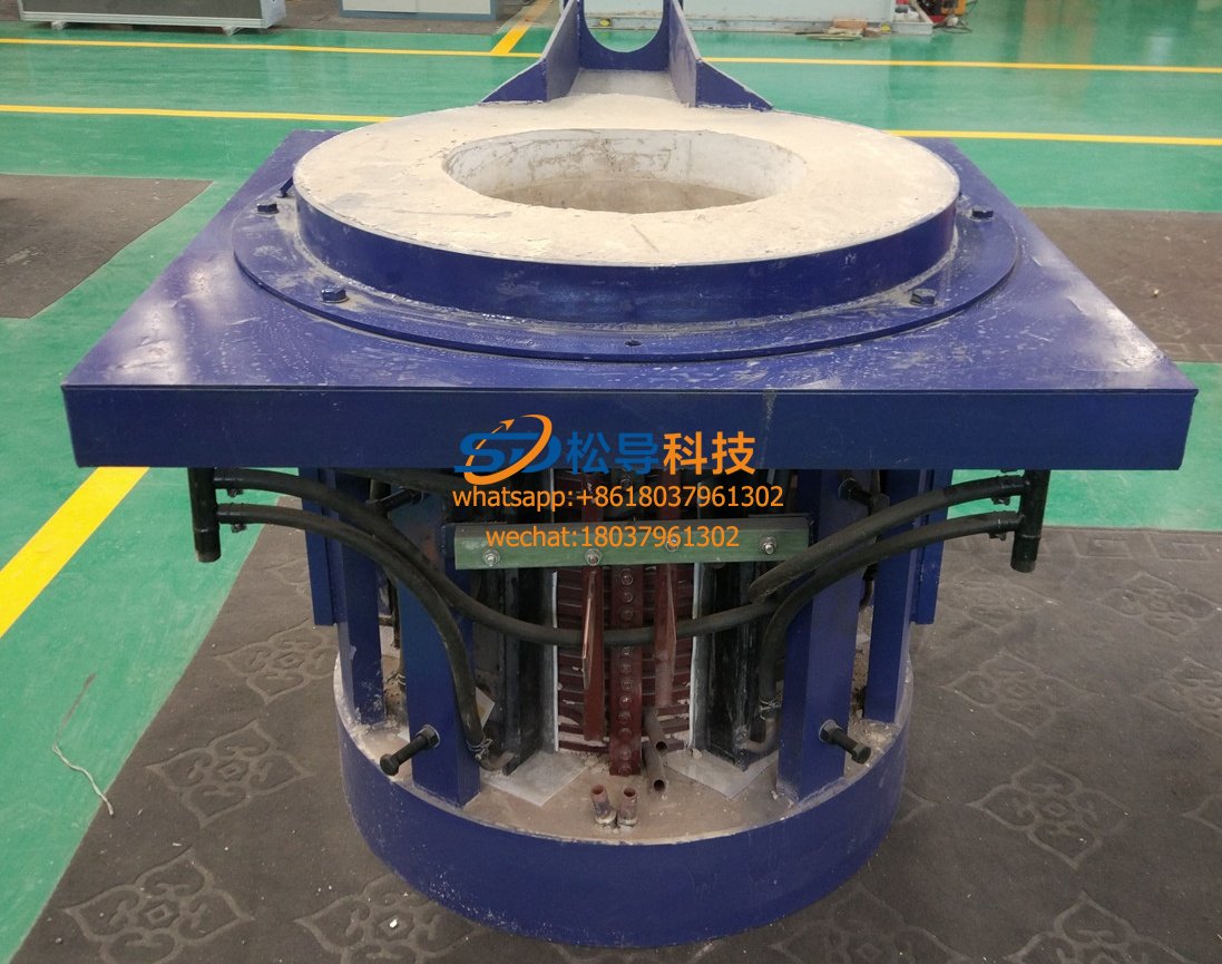
2 , induction furnace body
|
Serial number |
project |
parameter |
unit |
Remarks |
|
1 |
Single furnace rated capacity |
3 |
t |
|
|
2 |
Maximum capacity of a single furnace |
3.3 |
t |
|
|
3 |
Rated operating temperature |
1 80 0 |
°C |
|
|
4 |
Lining thickness |
110 |
Mm |
|
|
5 |
Melting material |
Cast iron, cast steel |
|
Hot melt from ordinary temperature to 1 80 0 ℃ |
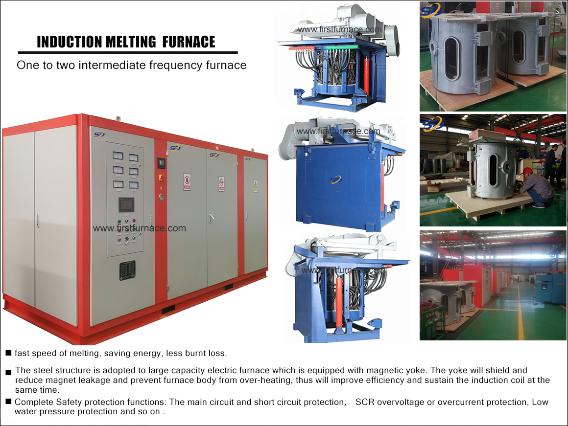
Equipment introduction
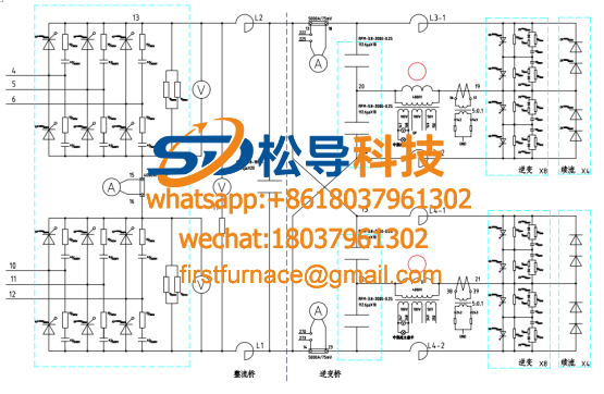
The circuit adopts 12-pulse rectification mode, and the incoming line voltage is 950 V. The inverter uses a half bridge inverter. The intermediate frequency power supply of such a line is suitable for a larger capacity electric furnace with a power of 2000 KW to 10 000 KW .
12-pulse IF power supply structure principle :
A , the rectifier part of the thyristor uses the latest stacked heat sink assembly. This installation method makes the thyristor disassembly and assembly more convenient and scientific. When replacing the thyristor, just loosen a top bolt , you can replace any thyristor component in the assembly. The radiator assembly has a scale for reference when tightening, which ensures the correct pressing force between the thyristor and the heat sink. Moreover, this mounting method substantially reduces the volume of the thyristor assembly and increases the operating space within the electrical cabinet.
B , large-capacity DC filter capacitor
The filter capacitor is very important for the solid power supply. It can make the output voltage of the rectifier smooth and stable, provide a stable and smooth voltage for the inverter, and make the inverter waveform stable and reliable.
C , inverter circuit uses large-capacity fast thyristor and freewheeling diode
In order to ensure reliable operation and reliable freewheeling of the inverter, the inverter thyristor and freewheeling diode adopt large-capacity KK thyristor and fast diode.
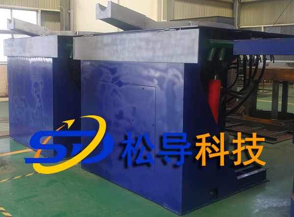
D, convenient power conversion function
Power conversion between the two furnaces is achieved by simply rotating the power conversion potentiometer on the panel. A furnace body is melted to melt the effect of another furnace bodyor two furnaces are simultaneously smelted. It can also be smelted in a furnace. The other furnace was shut down.
5.2 One to two intermediate frequency furnace power supply features:
Design and manufacture of thyristor series line IF power supply, its performance and reliability can be comparable with similar foreign products. The details are as follows:
5.2.1 Performance aspects
1: The rectifier bridge of the thyristor series power supply adopts full turn-on rectification. During the rectification process, the thyristor is always fully open. Therefore, the thyristor series power supply has the following advantages.
a: The power factor is high. Regardless of the furnace condition, whether full power, half power or low power, the overall power factor of the equipment is always ≥ 0.9 6 . Therefore, in terms of power supply and electricity, there are not only fines due to low power factor, but even rewards due to high power factor.
b : The rectified power supply adopts 12-pulse rectification mode . Compared with the six-pulse rectification , this rectification method can effectively suppress the 5th and 7th harmonics, and can effectively reduce the interference of harmonic components on the power grid. The resulting higher harmonic components are smaller and have less impact on the grid. Therefore, in an electric furnace in a large (more than 2 0 00KW) are using this rectifier.
2: The rectifier bridge of the thyristor series power supply is started by soft start, so there is no impact on the power grid when the power is turned on.
3: The inverter bridge of the thyristor series power supply adopts a voltage feedback type series resonance circuit, so the thyristor series power supply also has the following advantages.
a: High conversion efficiency. The three-phase power frequency alternating current is converted to an intermediate frequency single-phase alternating current conversion efficiency up to 97%.
b: high melting rate. The thyristor series power supply we produce can operate at constant power. No matter what kind of working state the furnace is in, it is oven, heat preservation or melting, and the power supply can adjust the running power at will.
c: High startup success rate. In any furnace condition, the startup success rate is 100%.
4: All the main circuits of the thyristor series power supply adopt large-section copper bars, and the power loss is only 20% of the water-cooled copper tubes.
5: The thyristor series power supply runs at low noise.
6: Perfect and appropriate protection.
a: Incoming current overcurrent protection. When the operating current of the device is greater than this value, the power supply stops and enters the protection state.
b: Incoming current limit, the line current of the limiting device operates below this value.
c: Capacitor voltage limit, the capacitor voltage of the limiting device operates below this value.
d: The electric furnace voltage is limited, and the electric furnace voltage limit of the limiting device is operated below this value.
e: The electric furnace current limit, the electric furnace current limit of the limiting device operates below this value.
f: Cooling water temperature protection. When the cooling water temperature is high, the power supply is protected.
g: Cooling water pressure protection. When the cooling water pressure is low, the power supply is protected.
7. Reliability aspects
1 : Control circuit board miniaturization.
2 : Control hub core integration.
8. The convenience of maintenance.
Considering the convenience of the user for maintenance, such as the installation of the thyristor, our thyristor uses a frame mount, and the thyristor is installed vertically, so that if the thyristor needs to be replaced, one can Easy to replace without the need for another person to help.
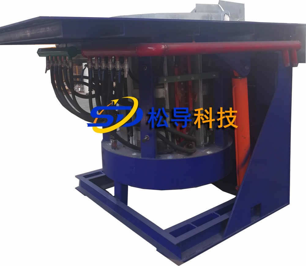
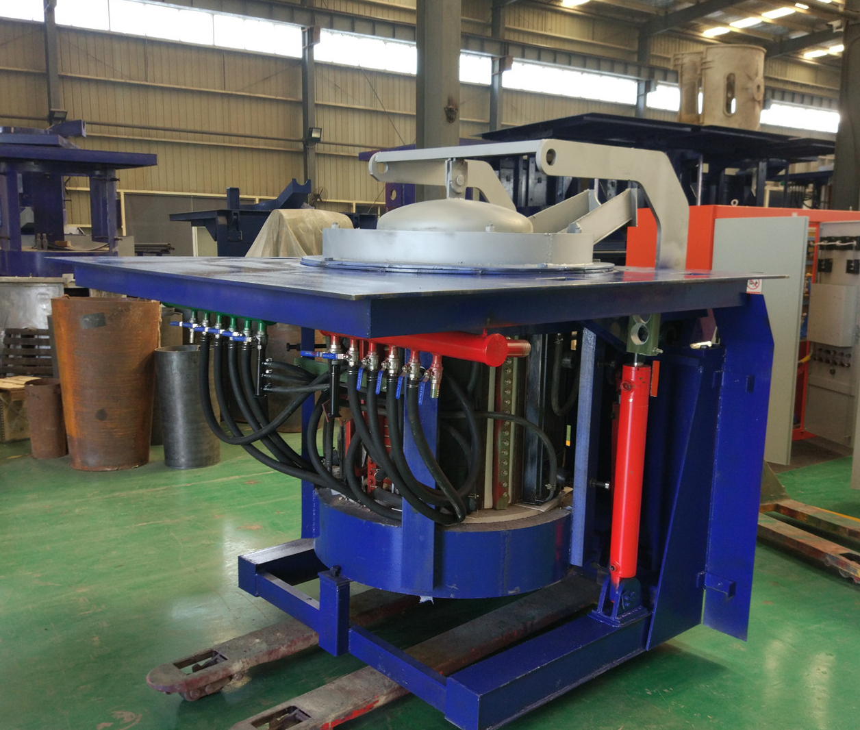
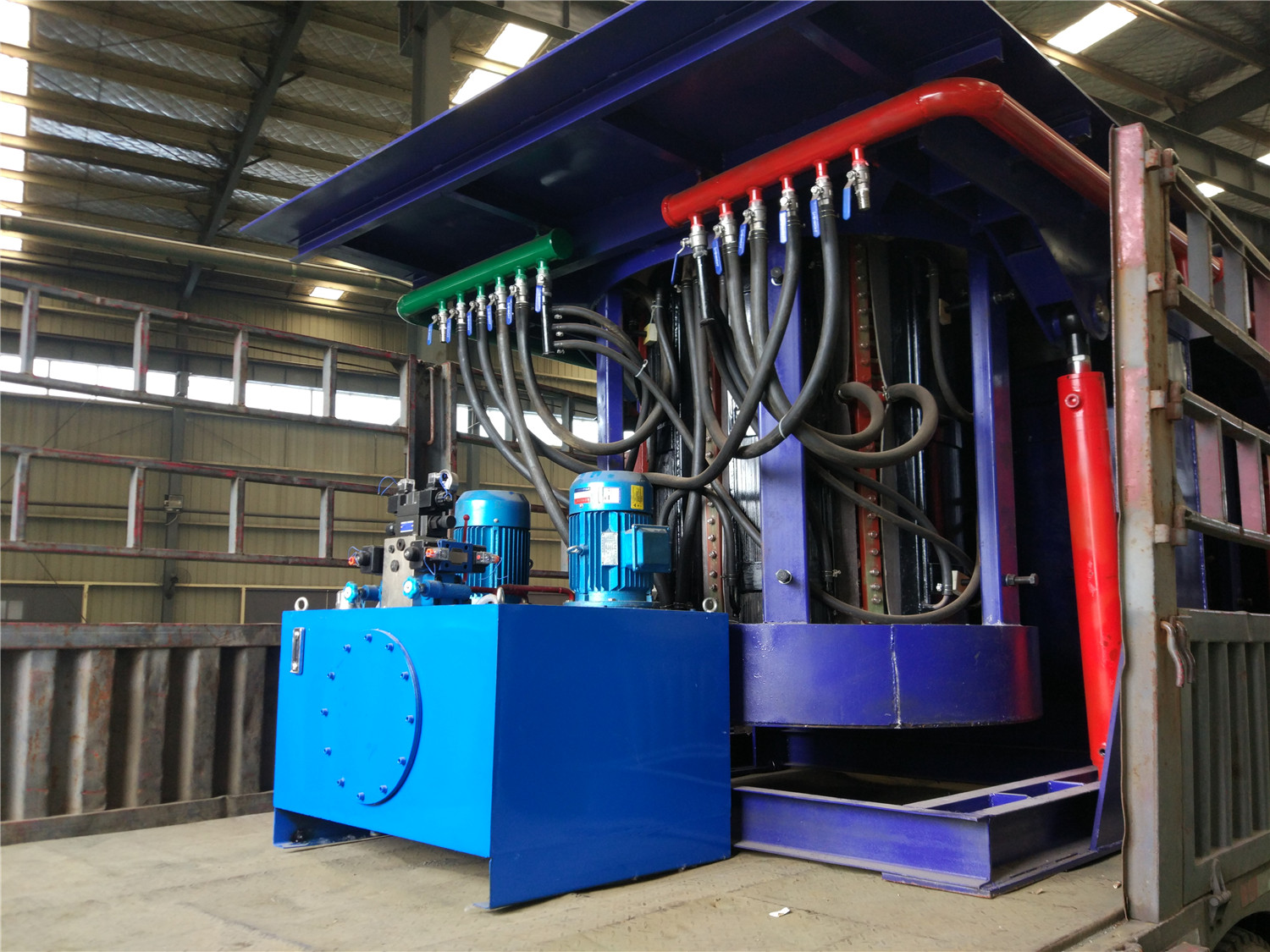
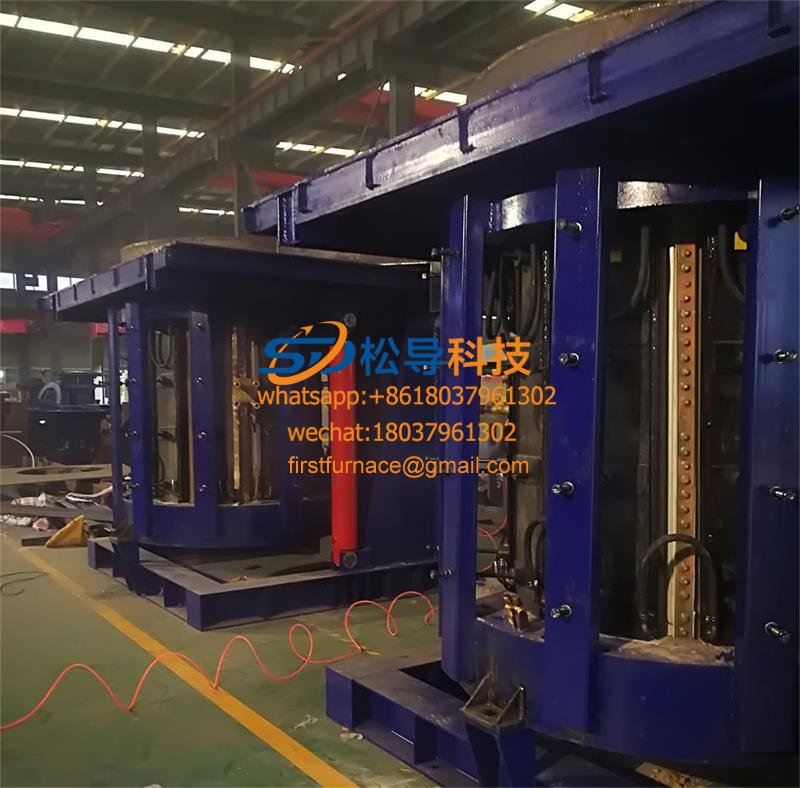
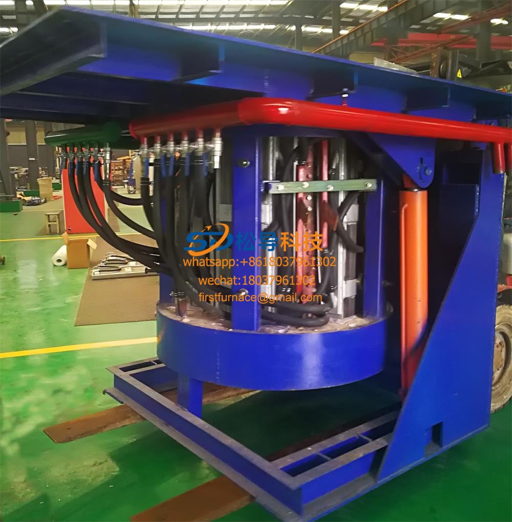
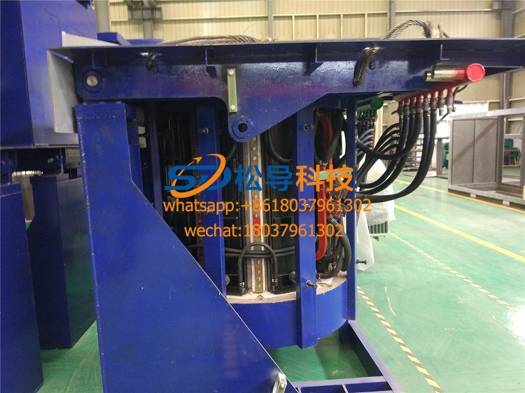
5.3 furnace body introduction
The electric furnace part includes an electric furnace body, a water-cooled cable, a refractory cement, a lining quick-release device, and a main circuit copper platoon.
5.3.1 Furnace body
The furnace body is composed of an induction coil, a yoke, a hob, a tilting cylinder (a holding furnace and a furnace cover).
5.3.1.1 Induction coil
The induction coil adopts the TU1 type grade (purity of 99.97% electrolytic copper), the pitch error of the crucible is not more than 2mm, and the coil group needs to be subjected to the stress relief treatment after welding. The induction coil is made of high temperature resistant, high pressure insulation paint, which is dip coated and vacuum dried. The insulation grade is H grade. The induction coil passed the 12kg/cm3 water pressure withstand test before leaving the factory. A stainless steel water-cooling ring is arranged on the upper and lower parts of the induction coil to ensure uniform heating of the furnace lining. A Faraday short-circuit ring is required at the upper and lower ends of the coil to fully absorb the leakage flux at the upper and lower ends to prevent the furnace body from heating up. The furnace body is connected to a large-section water-cooled cable, and the lead-out line is in the form of a side lead-out line. The coil pressing device is pulled down on the stainless steel rod.
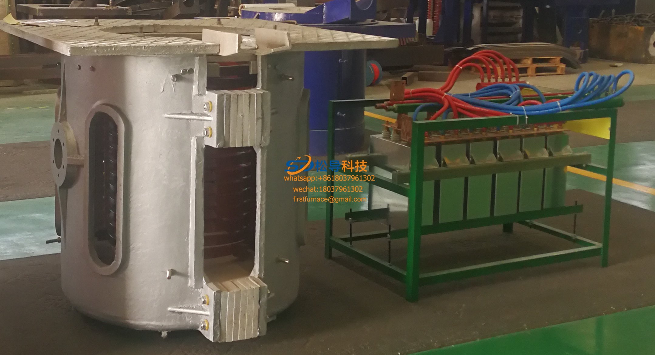
5.3.1.2 yoke
The yoke is made of a high permeability cold rolled silicon steel sheet. The thickness of the silicon steel sheet is 0.3 mm. The yoke adopts a profiling structure, and the arc of the inner arc surface is the same as the outer arc of the induction coil, so that the yoke can be evenly distributed on the outer side of the induction coil, thereby maximally restraining the magnetic field radiated outward from the coil and reducing the external magnetic circuit. Magnetoresistance.
The yoke is clamped by stainless steel plates and stainless steel clamps on both sides and fixed by welding. A cooling water pipe is welded to the stainless steel plate on both sides for cooling the yoke. The cooling water pipe can withstand 0.45Mpa water pressure and no leakage within 15min.
After the yoke is assembled, the bending degree is not more than 4 mm, and the deviation between the theoretical center line and the actual center line is not more than 3 mm.
A PTFE sheet and an asbestos rubber sheet are interposed between the yoke and the coil. The PTFE sheet has high dielectric strength and high temperature resistance, and the asbestos rubber sheet has high heat resistance. This ensures insulation and heat resistance between the yoke and the coil. Each yoke is fixed by a screw rod fixed on the furnace shell, and a uniform top force is formed in one circumference of the coil, so that the yoke is fixed and the coil is fixed, and the coil is not generated during the melting and discharging process. mobile.
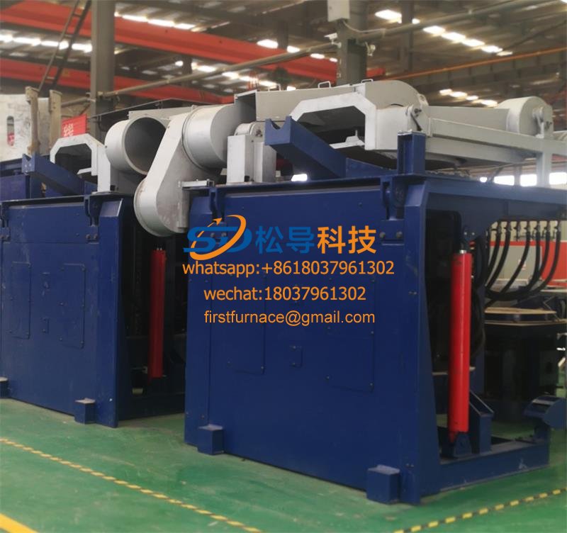
5.3.1.3 hob
The hob is divided into two parts.
5.3.1.3.1 Activity hob
The movable hob is used to mount the induction coil and the yoke. It is welded from profiled steel and steel plate and has a frame structure for easy maintenance. The operating platform at the top of the movable hob is made of thick steel plate to improve the strength and load-bearing capacity of the hob.
5.3.1.3.2 Fixed hob
The fixed hob is mounted on the foundation for carrying the movable hob. The upper part of the fixed hob is connected by the tilting shaft and the movable hob. Under the pushing of the tilting cylinder, the movable hob can be tilted forward by 95 degrees.
The hob section is designed with a large safety factor. Ensure that the hob has sufficient rigidity to run smoothly when carrying the maximum load.
5.3.1.4 Water-cooled cable
The connector of the water-cooled cable has a detachable structure and can be easily disassembled. The inside is connected to the copper strand by soldering. In this way, the connection is firm and the contact resistance is small.
The outer casing of the water-cooled cable is a rubber tube. This hose is not easy to burn and has good strength. It can withstand 0.45Mpa water pressure without leaking or breaking.
The rubber tube will age after long-term use and will be replaced at this time. This detachable structure does not need to damage the internal copper strands, and it is only necessary to disassemble the bolts on the joints to easily replace the outer rubber hoses.
The inside of the joint is sealed with a tapered cone and is electrically conductive. When the joint bolt is tightened, it naturally acts as both conductive and sealed.
5.3.1.4 refractory clay
Refractory clay is a highly insulating and insulating material that is applied to the inside and outside of the induction coil and has the following effects:
(1) Make the induction coil as a whole, reducing vibration and noise during operation.
(2) Protect the induction coil when the charge leaks.
(3) Conducive to the launch of the lining.
5.3.1.5 lining quick release device
The lining quick-release device is used to quickly remove the old lining. It includes a push block, a push cylinder and an operating mechanism.
The jacking block is mounted under the lining and is connected to the jacking cylinder through a pushing hole at the bottom of the furnace body. When the old furnace lining needs to be introduced, the electric furnace is tilted to 90 degrees, and the thrust pin is fixed by the fixing pin and the connecting flange at the bottom of the furnace body, and the old furnace lining can be pushed out by operating the manual valve to pressurize the oil cylinder.
Iron induction furnace
Aluminum melting furnace
Copper melting furnace
Small steel melting furnace
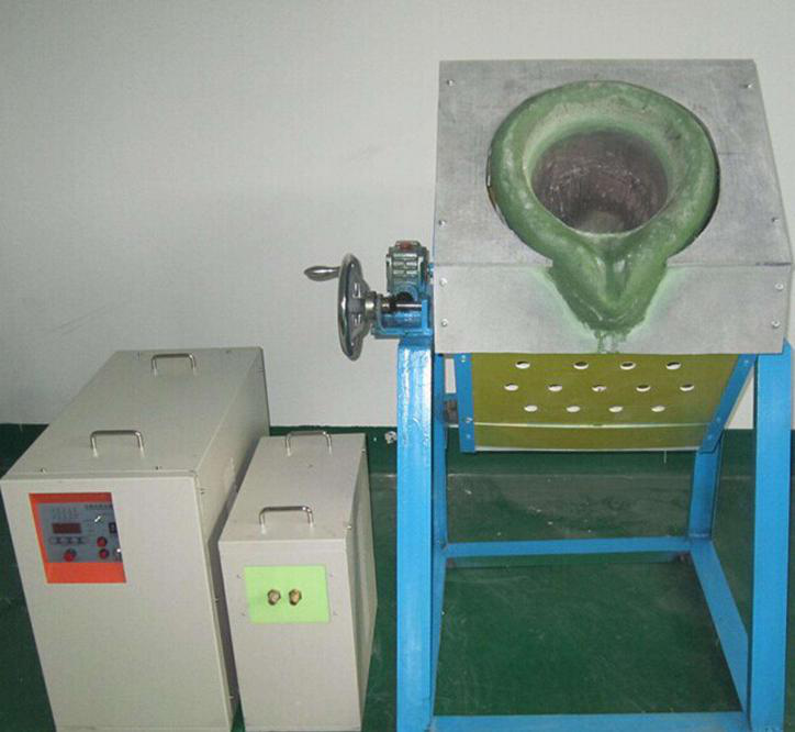
Small induction melting furnace
Induction iron furnace
3T intermediate frequency iron melting f

0.25T Intermediate Frequency Furnace

0.5T Intermediate Frequency Furnace

Medium Frequency Furnace

2T Induction Melting Furnace

1T Induction Melting Furnace

500kg Induction Melting Furnace

250kg Induction Melting Furnace

Induction Melting Furnace

3 T Induction Melting Furnace

5T Induction Melting Furnace
1T One Belt Two Intermediate Frequency F

5T One Belt Two Intermediate Frequency F
3T One Belt Two Intermediate Frequency F
2T One Belt Two Intermediate Frequency F
5T Parallel Intermediate Frequency Furna

5T Intermediate Frequency Furnace

5T Series Intermediate Frequency Furnace
3T Series Intermediate Frequency Furnace
2T Series Intermediate Frequency Furnace
1T Series Intermediate Frequency Furnace
0.5T Series Intermediate Frequency Furna

0.25T Series Intermediate Frequency Furn
1T Parallel Intermediate Frequency Furna
2T Parallel Intermediate Frequency Furna
0.5T Parallel Intermediate Frequency Fur