Sales hot line ( 24 hours service): 18037961302
E-Mail: firstfurnace@gmail.com
whatsapp:+8618037961302
Adress: Luoxin Industrial Park, Luoyang, HenanLarge diameter steel pipe quen
Piston rod quenching and tempe
Grinding rod quenching and tem
High frequency induction heate
Quenching equipment for machin
Round steel end heating furnac
Steel pipe heat treatment prod
Square steel quenching and tem
Sucker rod quenching and tempe
Thickened petroleum steel pipe
Round steel quenching and temp
Steel pipe quenching and tempe
Steel plate quenching and temp
Induction Hardening Machine&nb
Flywheel ring gear high freque
Requirements for working conditions of intermediate frequency induction melting furnace
1.1Power supply
(1)Strengage Station: llOkV/lOkV
(2)Three-phase alternating current: 380 V to 10 and 50 Hz to 2.
(3)single phase alternating current: 220V to 10V to 50 Hz to 2.
1.2、 compressed air: 0.5 MPa~0. 70 MPa.
1.3、Industrial water: municipal tap water.
1.4、Working hours: two shifts, 250 days per year
.
1、Technical requirements for intermediate frequency induction melting furnace
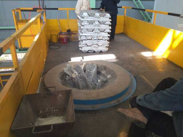
2.1、melting hot metal technical parameters and requirements
2.1.1、Hot metal grade: molten iron is mainly cast iron of HT250,HT300 and other grades.
2.1.2、the control precision of the main chemical composition of hot metal is C ±0. Si ±0. CE + 0.10; and add appropriate amount of Cu,Cr and other alloy elements.
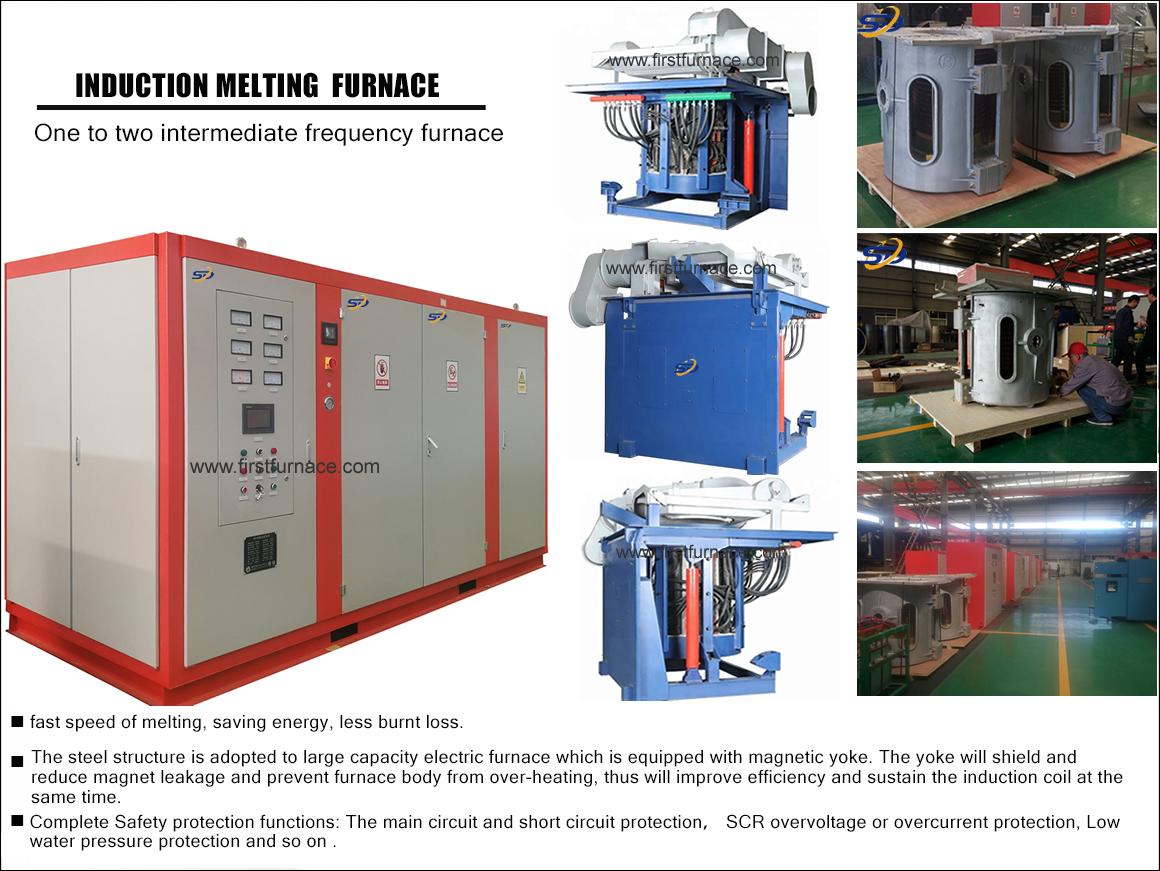
2.1.3、the intermediate frequency power supply of the melting furnace adopts "one towing one" single power supply type, that is, one power source of each set of electric furnace and one furnace connect to melt the solid iron material.
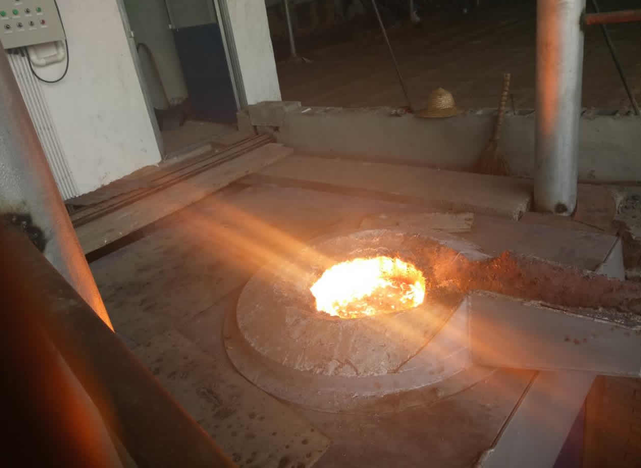
2.1.4、molten iron capacity: the actual melting of qualified iron per hour of electric furnace is more than 2T (excl. the auxiliary time of feeding, hot metal composition inspection, tempering etc.).
2.1.5、the furnace must melt and heat the 2T cast iron coolant in the furnace to 15000C within 60 minutes, and the power of the power supply shall be determined by the supplier himself.
2.1.6、 molten iron temperature: ≥ 1500 C.
2.1.7、melting power consumption: the temperature of molten iron is 1500 C, the average power consumption per ton of molten iron is less than 650 KW ・h.
2.1.8、ensure adequate electromagnetic stirring force for molten pool metals.
2.1.9、noise level: measured on the operating platform, 1 m from the stove, less than 85 db. after background noise.
2.2、equipment configuration and technical requirements
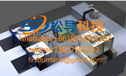
The melting furnace consists of medium frequency power supply, furnace body, hydraulic device, cooling water system, emergency water system, low-voltage control cabinet and so on. Equipment configuration and supply range
2.2.1, if power supply
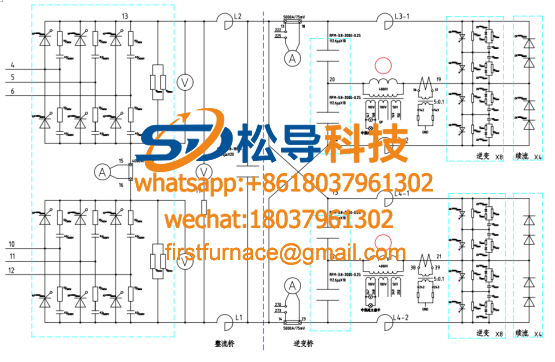
2.2.1.1、The rated power of intermediate frequency power supply is determined by the supplier, and the transformer capacity is determined by the supplier in the design of the single power supply of "one towing one". If power supply must be produced by well-known manufacturer, the SCR and capacitor in power supply must adopt well-known brand, control circuit and other main electrical components, such as reactor, transformer, trigger module, etc., should be stable and reliable. Cooling water hose must be carbon-free hose, power supply terminal must be equipped with automatic air circuit breaker. The power supply adopts 12 pulse rectifier. Power cabinet and control cabinet must have complete instrument and operation interface.
2.2.1.2、the power factor of the system is not less than 0. 95.
2.2.1.3、if power conversion efficiency: not less than 97. 5%
2.2.1.4,frequency conversion power supply must have frequency automatic tracking function, so that the power supply and furnace always keep the best match. The operator does not need to switch the connection of the capacitor so as to avoid the operational factors affecting the efficiency of the system.
2.2.1.5、the high order harmonics produced should meet the requirements of standard JB/T14549-93 power quality and public power grid harmonics.
2.2.1.6、the design of electrical components is reasonable, the discharge is neat, the maintenance and replacement of parts is convenient and quick, and all the major heating elements are equipped with reasonable cooling methods according to the need.
2.2.1.7、the success rate of if power supply must reach 100.
2.2.1.8、the power supply cooling water input with water pressure relay, control when there is no cooling water, do not start or cut off the intermediate frequency power supply.
2.2.1.9、in order to ensure the safety, stability and reliability of the if power supply in use, the following protection functions must be provided:
(1) main circuit short circuit protection
(2) thyristor overvoltage protection
(3) main circuit misphase protection
(4) cooling water temperature protection
(5) main circuit phase gap protection
(6) cooling water pressure protection
(7) thyristor overcurrent protection
(8) (leakage furnace protection
2.2.1. 10、 if power cabinet
(1)if power supply cabinet door is interlocked with power cut line, the main power supply is cut off when the electric cabinet door is opened, and the lighting working lamp and single-phase AC220V three-hole standard power outlet are installed in the control cabinet for inspection and maintenance.
(2)reasonable heat dissipation devices should be provided in the cabinet to ensure the clean and low temperature of the cabinet and avoid the pollution of unclean air.
(3)the cabinet door is enclosed with a seal and each door is fitted with a secret lock.
(4)the control cabinet should adapt to the working environment and have waterproof and dustproof structure. The sealing on the door should be oil-resistant and the protection grade should be IP55.
(5)the control cabinet is equipped with red, yellow and green display alarm light.
(6)equipment nameplate shall be affixed to the door of the control cabinet, indicating the manufacturer of the equipment, the date of departure, the serial number and specifications, model, input voltage, power, weight of the equipment, etc.
(7)the cable must be classified and numbered as required, indicating the category, transfer box number, terminal arrangement number; all control lines, power lines shall be threaded through the pipe, and the pressure terminal head shall be arranged on the terminal line.
(8)device identification in cabinet
A、all electrical components of the control cabinet shall be marked with Chinese instructions and numbers above them, and oak shall not be on the component body.
B、the text code of the logo should be consistent with the drawing.
C、the mark handwriting is clear and not easy to fall off.
D、each terminal and terminal row shall be marked and in accordance with the drawings.
2.2.1. 11、capacitor
(1)Non-toxic dielectric shall be used in capacitors.
(2)capacitors should be selected with large capacity, low dielectric loss, small volume, less heat, safety and reliability.
2.2.1. 12、Intermediate frequency power control cabinet
(1)The control cabinet is made of steel cabinet, which consists of control instrument, power control turntable, button switch and power indicator lamp.
(2)The control cabinet should ensure the convenience of operation and maintenance inspection.
2.2.2、rectifier transformer
2.2.2.1、The primary voltage of rectifier transformer is 10kV, and the rated capacity is determined by the supplier himself.
2.2.2.2、A manual voltage regulator is installed on the high voltage side of the transformer. Adjust the output voltage in 5%, 2. 5% and 5%
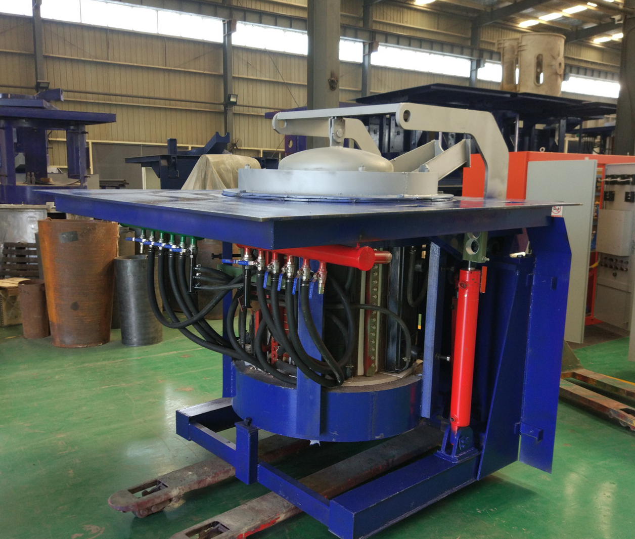
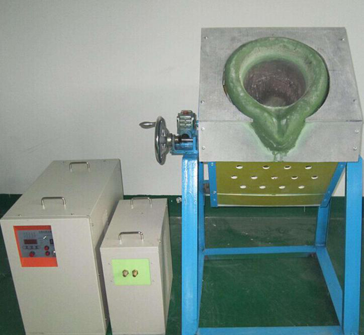
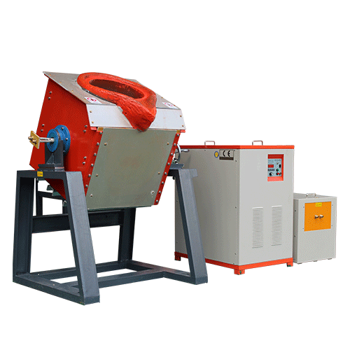
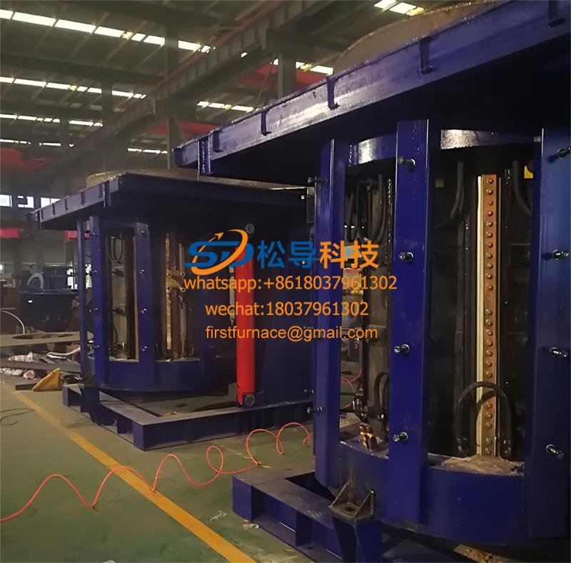
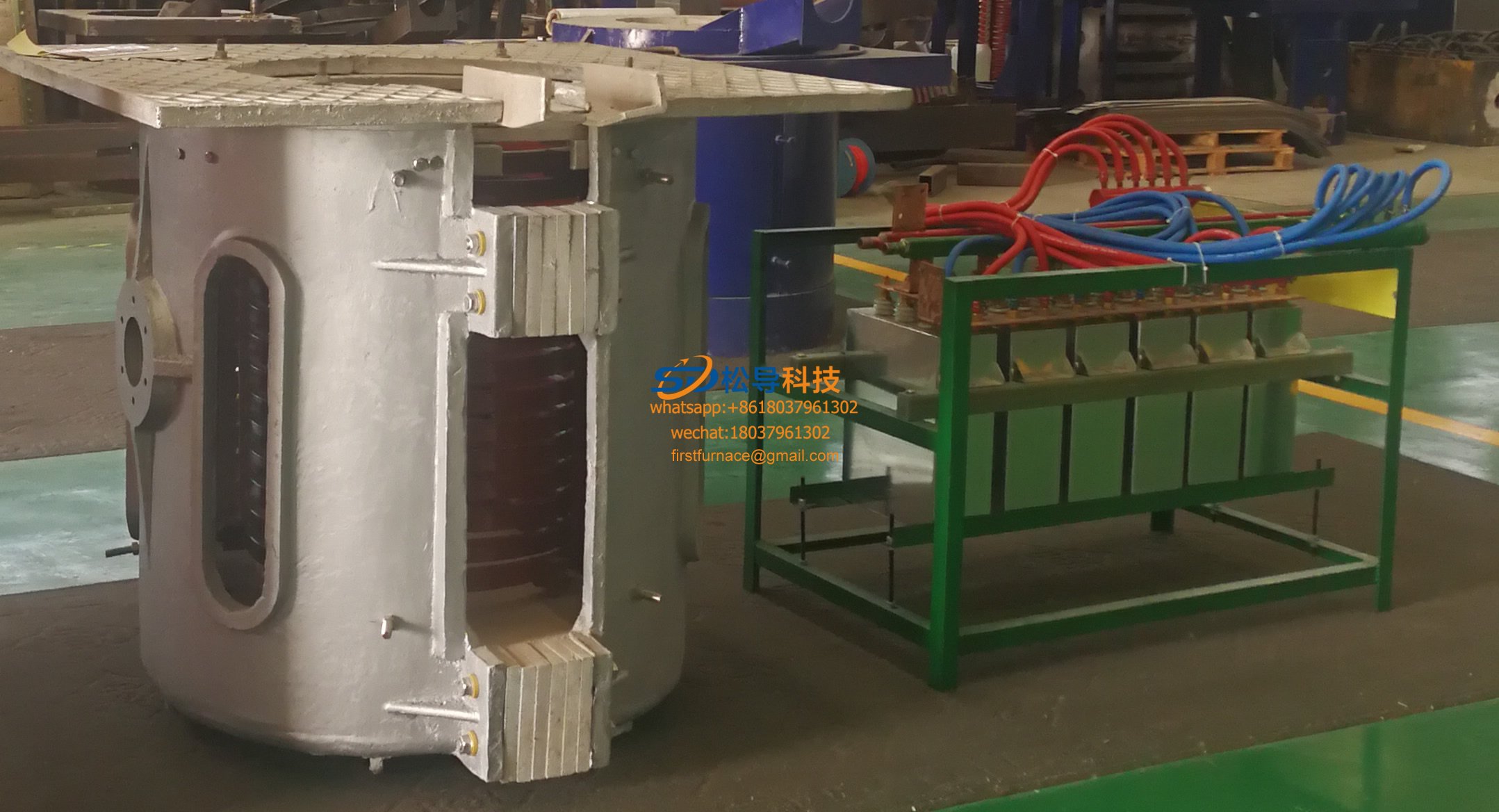
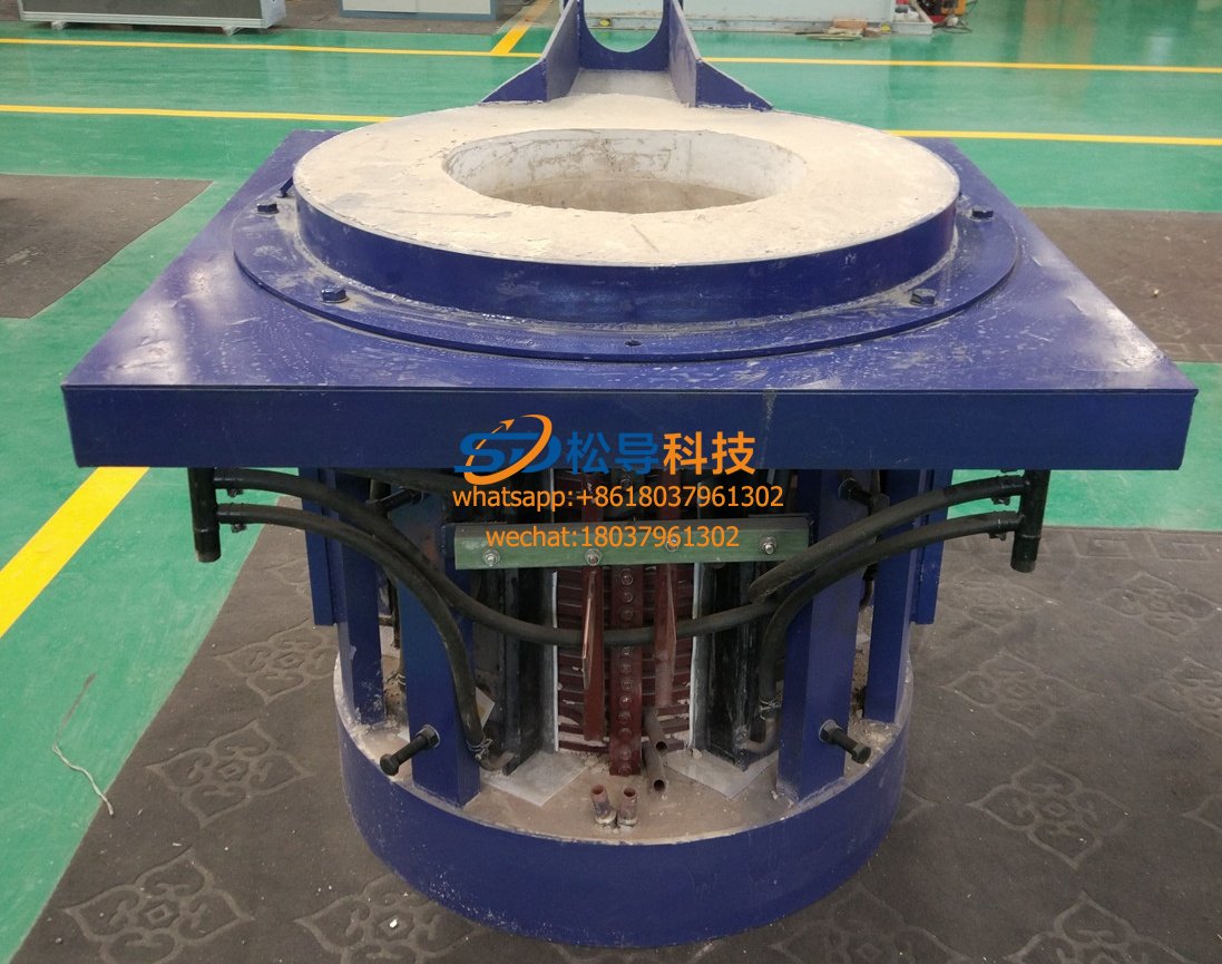
2.2.3、furnace body
2.2.3.1、The furnace body is composed of steel shell, furnace frame, induction coil, inlet and outlet pipe, distributor, yoke, high strength coil prop, refractory forming block, coil coating material, hydraulic tilting furnace oil cylinder and so on.
2.2.3.2、The rated capacity of furnace body is 2T.
2.2.3.3、furnace mantle
(1)high-quality thick steel plate is adopted. It is convenient to disassemble and assemble in structure and is convenient for maintenance.
(2)the lower part of the furnace shell has a fixed support for the lining ejection mechanism
(3)the furnace shell is equipped with analogue magnetic yoke.
(4)the furnace shell should not be deformed under the action of electromagnetic force, as well as the operation of tilting furnace and furnace village pushing.
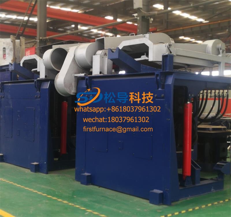
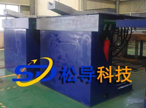
2.2.3.4、 tilting device
(1)The main results are as follows: (1) the tilting furnace adopts the hydraulic driving mode, the furnace body is inclined forward and the water is poured out, and the operation should be stable and reliable.
(2)there should be a protective cover for the tilting cylinder, which is not exposed when the furnace body is tilted, and there is a field operating table in front of the furnace.
(3)the tilting mechanism is designed with a device to prevent accidents caused by the sharp fall of furnace body caused by pipe rupture and so on.
(4) the maximum velocity (∞) of tilting mechanism is ≥90/min.
(5)the tilting furnace adopts manual speed regulation and commutation control, which is easy to operate.
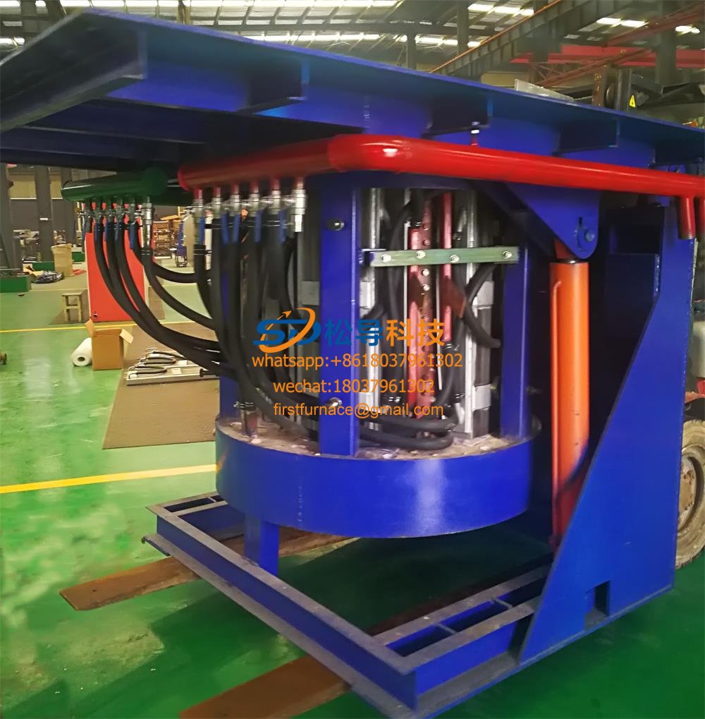
2.2.3.5、induction coil
(1)The material of induction coil is made of thick wall oxygen free copper tube with purity ≥ 99. 97.
(2)The selection of induction coil steel should ensure the rigidity of the coil and have the largest conductive section, the minimum copper loss and the highest electromagnetic conversion efficiency.
(3)The induction coil should be wound with high temperature and high pressure. The insulation grade is H, the insulation voltage is more than 5 000V, and the inductor coil is subjected to 8kg/cm2 hydraulic voltage test 36 hours and 5 000V before assembly.
(4)the inductive coil should be made to ensure that the lining is heated evenly, and the flux leakage from the upper and lower ends should be fully absorbed in order to save energy.
(5) the coil compaction device should be simple to disassemble and assemble the coil.
(6)A reliable and effective cooling method should be adopted for the confluence copper bar inside the power supply and connecting the power supply to the furnace body.
2.2.3.6、 fixed mount
(1)The fixed frame is mainly the supporting frame of the furnace shell, which is a high strength integral steel structure and must be operated for a long time without deformation.
(2)the furnace platform is made of patterned steel plate with thickness of not less than 6 mm.
(3)the noise on the working platform of the stove is less than 85db.
2.2.3.7、yoke
(1)The yoke is made of silicon steel sheet. Must be curved, exactly in line with the arc curve of the induction coil.
(2) the thickness of silicon steel sheet made of magnetic yoke is less than 0.3 mm, which is made by cold rolling process.
(3)the effective area of the yoke encircling coil should be more than 60.
2.2.3.8、Permanent lining
(1)Permanent lining for refractory mortar, coating thickness should be uniform, thick 10~15mm.
(2)The manufacture of the permanent lining should be convenient for the ejection of the lining and the ramming of the lining.
(3)The manufacture of the permanent lining should prevent the lining from being affected by the hot and cold deformation of the lining.
2.2.3.9、Leakage furnace alarm device
(1)In order to ensure the safety of production and prevent the occurrence and expansion of leakage furnace accidents, the electric furnace must be equipped with a crucible furnace alarm system.
(2)The configuration of leakage furnace alarm system should be advanced, safe and reliable.
(3)The alarm system of leakage furnace must send out the alarm signal of leakage furnace before the liquid iron reaches the inductor, and can judge the degree of leakage furnace.
(4)
In case of leakage of furnace and hot metal contact with induction coil, the operator of operation such as removing slag and measuring temperature will not be subjected to electric shock even if he holds a metal rod to contact the molten iron in the furnace
(5)The earth leakage can still be detected when the frequency conversion power supply stops working.
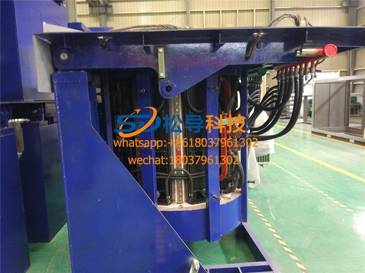
2.2.3. 10、Water-cooled cable
(1)Water-cooled cable is made of high quality T2 multi-strand copper strand, high strength flame-retardant rubber tube, cold pressing joint, good contact, strong tensile ability (according to the corresponding national standard JB/T 10358-2002 industrial electric heating equipment water cooling cable execution)
(2)Water cooled cable in high temperature working environment, do not deform, contact well
(3)Water-cooled cables to be protected against molten metal spatter damage
2.2.3.11 Furnace body must be equipped with furnace pit safety protection device.
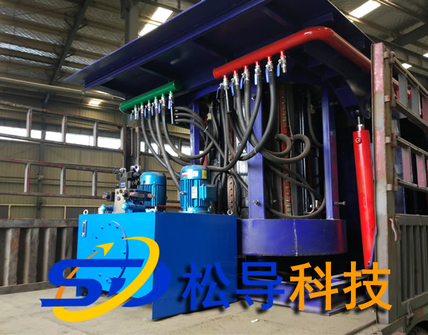
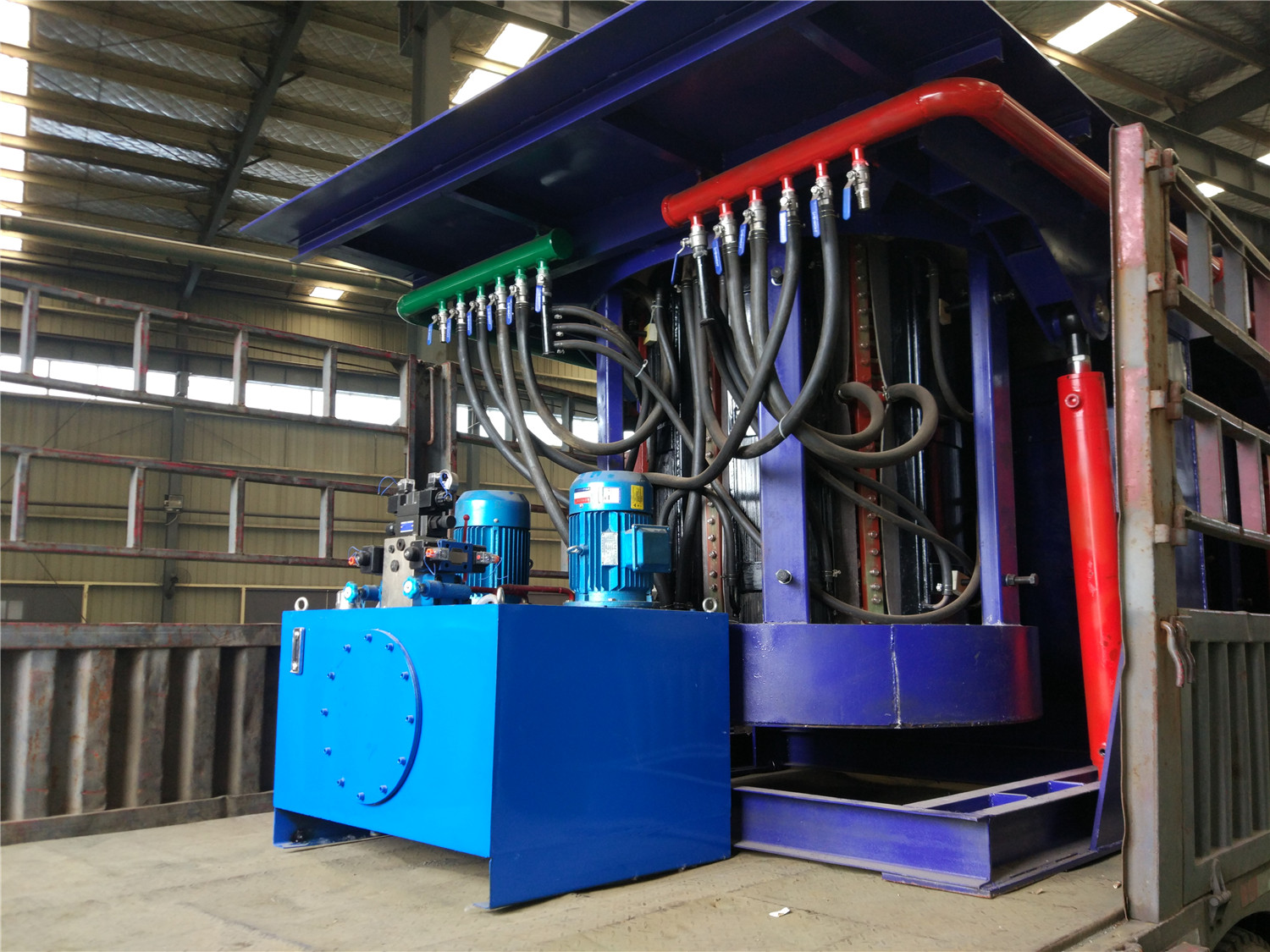
2.2.4、hydraulic unit
2.2.4.1、The hydraulic device consists of two parts: hydraulic pump station and hydraulic operating table.
2.2.4.2、Hydraulic pump station with two-machine dual-pump integration unit, one working, one standby, can be automatically switched.
2.2.4.3、Hydraulic device to ensure reliable operation, to ensure that the whole system hydraulic oil leakage
2.2.4.4、The main hydraulic components are imported brand. The tank has liquid level display, oil level detection alarm, pressure detection alarm. The working pressure can be adjusted according to the actual need value. Hydraulic pumps and hydraulic operating valves use imported products.
2.2.4.5、Hydraulic system shall have filtration, oil temperature heating and cooling, oil temperature control and other devices.
2.2.4.6、Hydraulic station has oil filtration, oil filtration device, filtration accuracy exceeding hydraulic pump and hydraulic valve specified precision standards. The filtered oil should be above the NAS 1638 standard.。
2.2.4.7,Check valve door shall be provided for hydraulic cylinder inlet pipe. The fixing of hydraulic oil pipe should be convenient for operators to overhaul and fasten.
2.2.4.8、The hydraulic pipeline should be treated with anti-fouling, and the convenience of oil exchange operation should be considered.
2.2.4.9、The supplier shall explain the following main performance parameters of the hydraulic pump station: maximum working pressure, working flow, hydraulic medium, maximum oil temperature, hydraulic station capacity.
2.2.4. 10、Hydraulic operating table
(1)The hydraulic operating table is installed on the furnace table to control the tilting of the furnace body and the work of the furnace lining ejection mechanism
(2)Manual valve operation
(3)Work reliably, smoothly, without shock and climbing
(4)The speed of the tilting furnace is adjustable and can stay in any position
(5)Two hydraulic quick changers should be reserved for the hydraulic operating table
2.2.5、cooling water system
2.2.5.1Summary:
The closed cooling water system should be used in furnace body and if power supply, and the cooling system should be equipped with reliable emergency cooling system. Once the power grid is out of power, the emergency cooling system should be started immediately to ensure the safety of furnace body equipment. The cooling water system should be equipped with water temperature sensor, water pressure sensor, flow sensor and other devices to monitor the temperature, pressure and flow rate of cooling water. The outlet temperature of each outlet pipe should be displayed by a centralized digital instrument, and the water temperature in the pipeline should be displayed online. Performance of closed cooling tower with related electric furnace cooling system。
2.2.5.2、The design of water system should be advanced in design, compact in structure, less in area, superior in performance and remarkable in cooling effect. The whole equipment should be safe and reliable.
2.2.5.3、Cooling water of the cooling system needs to be circulated in closed pipes and cannot be contacted with the atmosphere.
2.2.5.4、The closed circulation system should be fitted with pressure regulating valves that can adjust the pressure of the cooling system at any time.
2.2.5.5、The equipment shall be equipped with pressure relays, pressure gauges, thermometers, indicating water pressure and temperature, and equipped with pressure switches and temperature switches, water pressure regulating switches, etc., which can be used to measure and monitor cooling water systems for a long time.
2.2.5.6、If the pressure and temperature of the system are abnormal, the if power supply can be cut off automatically and an alarm signal can be issued at the same time.
2.2.5.7、Cooling water hose should be carbon-free hose, hose layout should be simple, reasonable, easy to maintain.
2.2.5.8、The supplier shall state the inlet pressure, inlet temperature, outlet temperature, flow rate, and cooling water quality requirements of the cooling water system in the tender document.
2.2.5.9、Circulating water pump station
(1)The circulating water pump station consists of two exchangeable pumps, automatic pressure regulating devices, monitoring instruments, water purification plus pump stations and control cabinets.
(2) Pressure gauges, temperature switches and sensing elements are installed in each inlet and outlet manifold to detect and display the pressure and temperature in and out of the water.
(3) The spray pump and cooling fan can be started automatically when the temperature of cooling water reaches the set value.
2.2.5. 10、Closed cooling tower for cooling system
(1)Cooling water systems require copper tube cooling towers and stainless steel pumps. Valves, piping and fittings shall be of copper or stainless steel.
(2) The circulating water discharge of power cabinet should be lower than the set value, there is flow alarm.
(3)When the inlet and outlet temperature of circulating water exceeds the set temperature, there is a temperature alarm device and cut off the power supply.
(4)Equipped with air-water separation and automatic exhaust valves, the system can automatically discharge the accumulated gas and improve cooling efficiency.
(5)When circulating water is depressed under working pressure, there is a pressure alarm and if power supply is cut off
2.2.5. 11、The furnace body and the power supply share a closed cooling water system
2.2.5. 12、Emergency water system
(1)The electric furnace emergency water system shall have two levels: the first stage is the emergency pump water supply system connected with the emergency power supply; the second stage is the emergency water system connected with the tap water.
(2) When the cooling water system of furnace body breaks down or power supply fails, the power supply of the main system can be cut off quickly, the emergency pump water system connected with emergency electricity can be put into operation immediately within 10 seconds, and when the fault is removed, the emergency water system can be automatically removed. The emergency power supply time is ≥ th, to ensure that there is enough time to deal with the hot metal in the electric furnace and the furnace.
(3)The second stage of emergency water system is that the cooling water is directly connected with the existing tap water supply interface of our company and is equipped with filter device, which can be put into operation quickly when emergency electricity and emergency pump fail or when the time is too long, so as to ensure the safety of electric furnace.
(4)Emergency water system will alarm when the water supply pressure is less than the set value.
2.2.6、Water cooling systems and hydraulic system control cabinets
2.2.6.1、Low-voltage switchgear is mainly auxiliary equipment equipped with distribution cabinets, is the control water system and hydraulic system.
2.2.6.2、The control cabinet shall be suitable for working environment and have waterproof and dustproof structure. The sealing on the door shall be oil resistant and the protection grade shall be IP55.
2.2.6.3、The control cabinet shall be equipped with heat dissipation device to ensure that the working temperature in the cabinet is less than 350 C.
2.2.6.4,The control cabinet is equipped with red, yellow and green three-color display alarm light.
2.2.6.5、The control cabinet is equipped with a lighting working lamp and a single-phase AC220V three-hole, two-hole power outlet.
2.2.6.7、The door of the control cabinet shall be affixed with the equipment nameplate, indicating the manufacturer, the date of departure, the serial number and specifications, model, input voltage, power, weight of the equipment, etc.
2.2.6.8、The cable must be classified and numbered as required, indicating the category, transfer box number and terminal number; all control lines, power lines shall be threaded, terminal head pressed, and arranged on the terminal line.
2.2.6.9、Cabinet device identification
(1)All electrical components of the control cabinet shall be marked with Vietnamese instructions and numbers above them, and shall not be marked on the component body
(2)The text code for the logo should be consistent with the drawing
(3)The mark handwriting is clear and not easy to fall off.
(4)Each terminal and terminal row shall be marked and in accordance with the drawings
2.2.7、lubricating arrangement
2.2.7.1、As far as possible, centralized lubrication should be used in the lubricating parts of the equipment in operation, and the lubricating point or surface of the oil (grease) should be supplied according to the period of time.
2.2.7.2、Lubricating device should have visual oil gauge, flow is easy to adjust.
2.2.7.3、Lubricant adopts international famous brand
2.2.7.4、Type plate of lubricating oil suspended at refueling port。
2.2.7.5、Indicate the lubrication point on the equipment.
2.2.8、Computer melting management system
2.2.8.1、Frequency conversion power supply should be equipped with computer melting management system, the system should have perfect monitoring, alarm and failure.
Self-diagnostic function with perfect sound and light alarm. And to the following situation to make the alarm, feedback various faults.
(1)Frequency conversion power cabinet open
(2)The temperature of cooling water in power supply is too high
(3)Power cooling water pressure is too low
(4)The temperature of cooling water in furnace is too high
(5)The temperature of cooling water in furnace is too high
(6)Furnace selection / disconnect switch error
(7)Frequency conversion power source rectifier part without DC output
(8)Earthing / leak furnace detector alarm
2.2.8.2、The computer melting management system requires perfect melting and heat preservation process control, and its main functions include:
(1)Continuous monitoring and display of parameters
(2)Display and record system alarm, in addition to the sound and light alarm, can also store 100 alarm information, for maintenance and troubleshooting convenience
(3)Display the running state of the system
(4)Cold furnace start-up
(5)Monitor incoming line voltage and compensate for input voltage fluctuation within a certain range
(6)Automatic fault diagnosis
2.2.8.3、Starting current automatic control, power adjustment knob at any position can achieve "soft start", but also can continuously monitor and display various main parameters and realize manual real-time operation and program operation.
2.2.8.4、High power supply turned on, shut down, reset
2.2.8.5、Automatic and accurate diagnosis and display of system faults (including cooling system, main components of inverter in power cabinet, etc.). In case of abnormal condition, there is a systematic alarm display and call.
2.3Standard for execution of intermediate frequency induction melting furnace equipment
2.3.1、Provide equipment to meet safety, environmental standards, and key technical indicators such as atmosphere (dust, harmful gas concentration), noise, etc.
2.3.2、Electrical equipment supplied by the supplier should comply with CE safety standards
2.3.3、The noise when the equipment is in operation is below 85dB (A), according to the Chinese national standard GB/T 16769-2008.
2.3.4、Exhaust emission standard, the implementation of GB16297-1996 [Comprehensive Air pollution Emission Standards] table II level 2 standard.
2.3.5、Implement GB 22.1-2007 and GB 22. 7 for workplace hazards. National Occupational Health Standard 2-2007.
Iron induction furnace
Aluminum melting furnace
Copper melting furnace
Small steel melting furnace
Small induction melting furnace
Induction iron furnace
3T intermediate frequency iron melting f

0.25T Intermediate Frequency Furnace

0.5T Intermediate Frequency Furnace

Medium Frequency Furnace

2T Induction Melting Furnace

1T Induction Melting Furnace

500kg Induction Melting Furnace

250kg Induction Melting Furnace

Induction Melting Furnace

3 T Induction Melting Furnace

5T Induction Melting Furnace
1T One Belt Two Intermediate Frequency F

5T One Belt Two Intermediate Frequency F
3T One Belt Two Intermediate Frequency F
2T One Belt Two Intermediate Frequency F
5T Parallel Intermediate Frequency Furna

5T Intermediate Frequency Furnace

5T Series Intermediate Frequency Furnace
3T Series Intermediate Frequency Furnace
2T Series Intermediate Frequency Furnace
1T Series Intermediate Frequency Furnace
0.5T Series Intermediate Frequency Furna

0.25T Series Intermediate Frequency Furn
1T Parallel Intermediate Frequency Furna
2T Parallel Intermediate Frequency Furna
0.5T Parallel Intermediate Frequency Fur