Sales hot line ( 24 hours service): 18037961302
E-Mail: firstfurnace@gmail.com
whatsapp:+8618037961302
Adress: Luoxin Industrial Park, Luoyang, HenanLarge diameter steel pipe quen
Piston rod quenching and tempe
Grinding rod quenching and tem
High frequency induction heate
Quenching equipment for machin
Round steel end heating furnac
Steel pipe heat treatment prod
Square steel quenching and tem
Sucker rod quenching and tempe
Thickened petroleum steel pipe
Round steel quenching and temp
Steel pipe quenching and tempe
Steel plate quenching and temp
Induction Hardening Machine&nb
Flywheel ring gear high freque
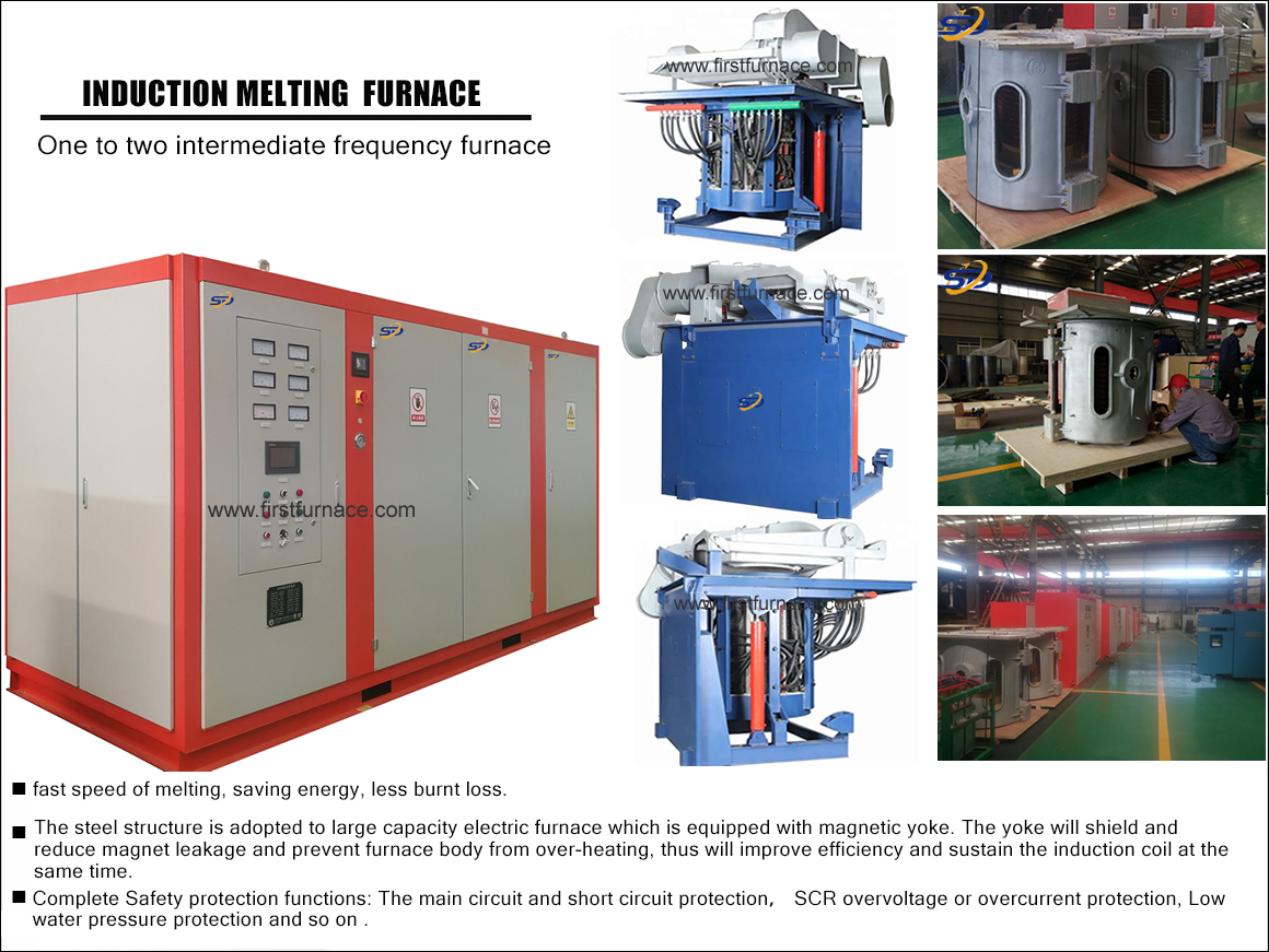
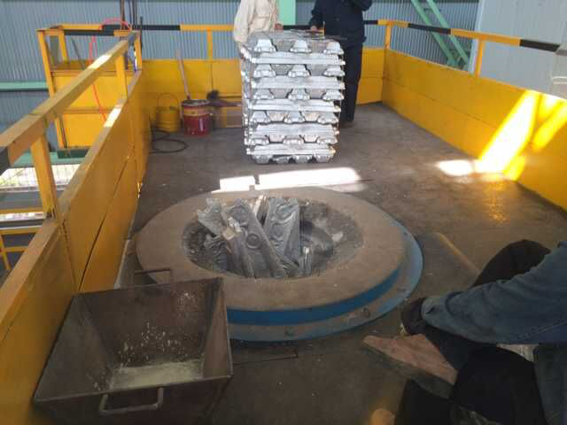
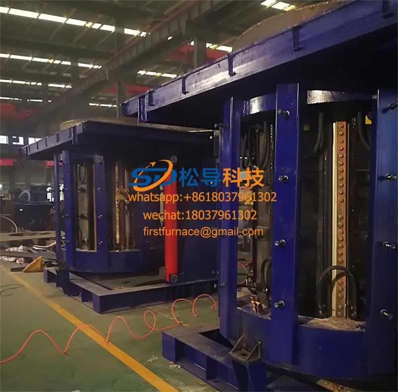
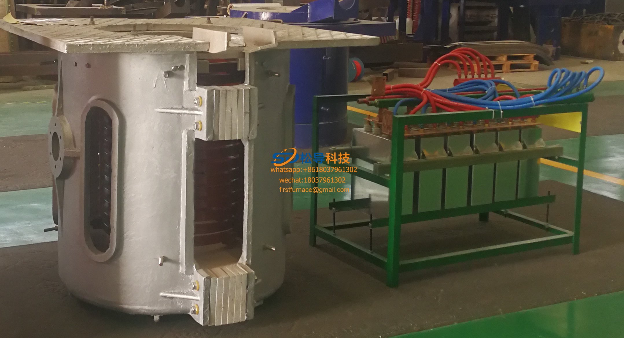
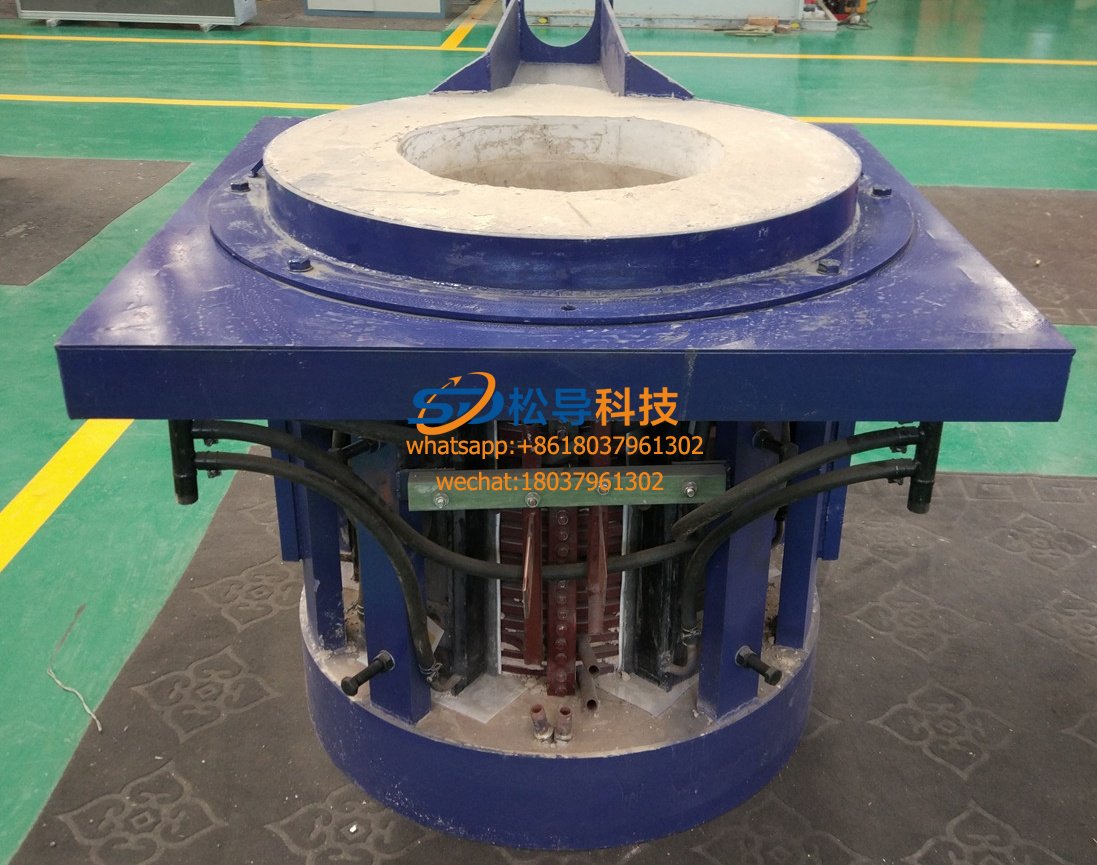
3 tons steel melting furnace technical principles and analysis
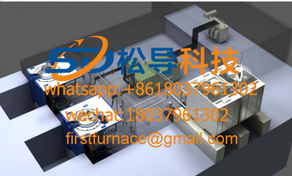
3 tons steel melting furnace equipment consists of a full rectifier power transformers, bus bars, low voltage isolating switch cabinet, a single power frequency power supply, the power control box 3 ton electric furnace body, pump stations, console tilting furnace, water-cooled cables, cooling water dispenser , mold, water cooling system and other components.
First, the power rectifier transformer
10KV power rectifier transformer for high-voltage power supply down to a voltage suitable intermediate frequency (output voltage is determined by the design and production units themselves). 3 tons steel melting furnace using a dedicatedrectifier transformer 2000KVA, ONAN. 10KV ± 5% of the primary voltage of the transformer, the secondary voltage of 660 V ± 5% (for reference, the output voltage is determined by the design and production units themselves). D/Y-11, d0 wiring form, six-phase output.
The short-circuit impedance of the power transformer ranges from 6% to 8%. The unloaded manual voltage regulator switch is installed on the high voltage side of the transformer, and the output voltage can be adjusted in the third gear of -10%, 0, +10%. The power transformer is equipped with a gas relay and an oil temperature meter, and its output is interlocked with the high voltage switch cabinet. When the transformer has a gas alarm or the oil temperature is too high, the high voltage is automatically cut off.
Second, low voltage isolation switch / power control cabinet
Rated current 2 500A, 6 phases. Connected between the power transformer and the intermediate frequency power supply for isolation and maintenance of the intermediate frequency power supply. A voltmeter for monitoring the secondary output of the transformer, an ammeter, and a watt-hour meter for statistical energy consumption are mounted on the low-voltage switchgear. Its function is: the first is used to isolate the transformer and the intermediate frequency cabinet, and the power is cut off during the maintenance of the intermediate frequency cabinet. The second low-voltage isolated power cabinet simultaneously controls the operation of the oil pump and the water pump, provides power control to the hydraulic oil pump, the water pump, the illumination lamp, etc., and connects these devices to the backup power source when the main circuit is powered off. It has 2 inputs, which are connected to the main power supply and the backup power supply (can be generator sets or others). In addition to the normal use of pumps, oil pump cooling towers, etc., two outputs are provided for standby.
Third, the intermediate frequency power supply
A 2000KW single-supply intermediate frequency furnace is used . Power semiconductors use thyristor half-bridge series inverter inverter .
3 tons steel melting furnace frequency power supply should have the following features:
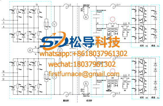
1, the rectifier circuit
The IF power supply uses a 12-pulse thyristor bridge rectifier circuit. At least 11th harmonic; the grid side power factor is always greater than 0.95; no control is required.
The rectifier transformer of the intermediate frequency power supply adopts D/Y -11 , d 0 wiring form, and the transformer has two sets of three-phase output twice. The line voltages of the two sets of outputs are equal, all are 660 V, but the phase difference is 30 ° . The two sets of outputs are connected to the I and II sets of rectifier bridges respectively.
The thyristor of the rectifying part adopts a stacked heat sink assembly; the heat sink assembly has a scale for reference when tightening to ensure the correct pressing force between the thyristor and the heat sink.
2, inverter circuit
A half bridge series inverter is used. The electric furnace is capable of outputting rated power when it is cold, hot, half-filled or filled. The half-bridge series inverter regulates the output power by changing the operating frequency.
3. Control system
The IF power supply uses an advanced digital control system based on a high-performance microcontroller.
(1) Digital inverter control
The digital inverter controller is integrated inside the CPU. Three closed-loop control algorithms for power, voltage and current are used. During normal operation, the voltage, current and power are sent to the CPU through their respective converters. The control software detects these parameters and adjusts the operating frequency to ensure that the output power is always equal to the rated power.
When there is an empty furnace power transmission (too much impedance) or a cold furnace power transmission (impedance is too small), the control software can automatically call the voltage limit or current limit algorithm to limit the output voltage or current not to exceed the allowable.
The control software has a variety of parameter limits, including:
Maximum power limit
Thyristor current output limit
Electric furnace voltage limit
Capacitor voltage limit
Maximum and minimum operating frequency limits
The parameters of the control algorithm can be set by the keyboard and they are stored in the EEPROM of the control board. The parameters are easily changed, making the half-bridge series inverter suitable for melting different metals such as cast iron, copper, aluminum, etc.
The thyristor is a controlled shutdown device, and the startup of the inverter is completely controlled by the trigger pulse, so the inverter can be 100% activated in any furnace condition.
(2) Multi-point temperature monitoring
The control system has digital multi-point temperature monitoring function. Each control panel can detect the temperature of more than 70 points at the same time. The upper limit alarm temperature of each point can be set separately.When the temperature of a certain point exceeds the set alarm temperature, the control system will automatically give a prompt, and the alarm signal will automatically turn off the intermediate frequency furnace after a certain period of time (usually 10S) .
(3) Comprehensive protection function
The protection measures of the control system include:
High grid voltage
Low grid voltage
High DC voltage
Thyristor current exceeds
High capacitor voltage
Electric furnace voltage is high
High working frequency
Cooling water temperature is high
Cooling water pressure is low
Low cooling water flow
Electric furnace leak furnace
(4) Automatic restart function
When overcurrent, overvoltage, high inverter frequency protection occurs (the occurrence of these protections does not indicate equipment failure, often caused by sudden feeding, furnace collapse, rapid fluctuation of grid voltage, etc.), the intermediate frequency power supply will disappear after the protection signal disappears 2 The second automatically restarts and resumes normal operation.
(5) Delay protection function.
When the grid voltage is high, the grid voltage is low, the water temperature is high, and the water pressure is low, the IF power supply does not stop immediately. Instead, the protection signal is first indicated. If the protection signal still exists after 10 seconds, the shutdown enters the protection state. Because the above phenomenon will not cause any equipment damage within 10 seconds, on the contrary, the delay protection can filter out some mis-protection. For example, when a large electric appliance in the vicinity of the equipment is suddenly closed or opened, the grid voltage will fluctuate instantaneously. It usually returns to normal after a few seconds. In this case, the IF power supply will continue to operate normally.
(6) with liquid crystal graphic display
The control system has a dedicated LCD graphic display. The display is installed on the operation panel of the intermediate frequency power supply. When the intermediate frequency power supply works normally, the working parameters of the intermediate frequency power supply, the working state and the multi-point temperature monitoring result are dynamically displayed. If the IF power supply is abnormal, it will display the cause of the fault or protection, and automatically memorize the trip source so that the service personnel can quickly troubleshoot according to the prompts.
(7) Fiber isolation pulse output
In the control system, the trigger pulse is optically isolated from the control board to the gate of the thyristor by using a fiber isolation technology.
(8) has a computer communication interface
The control system has a computer communication interface, which can be connected to the melting management computer to realize centralized monitoring of parameters of multiple intermediate frequency power supplies. The communication interface uses optical fiber as the communication medium to ensure the reliability of long-distance data transmission.
(9) With leakage furnace protection and grounding alarm trip function
The control system has a dedicated lining thickness detector. The alarm current of the lining thickness detector can be adjusted.
(10) Computer Melting Control Management System
A computer system for data sampling and control based on industrial control computers, used for automatic control and data recording of melting or processes, its main functions:
Basic monitoring: continuous monitoring and display of meter readings of variable frequency power supplies
power
Furnace current
Furnace voltage
frequency
Capacitor voltage
Ground leakage current
Total kilowatt hour value
System alarm display
Capacitor damage or door opening
Overvoltage protection
Internal cooling water temperature is too high
Internal cooling water pressure is too low
External cooling water temperature is too high
External cooling water pressure is too low
Furnace selection / isolation switch error
AC interrupt
Ground/leak detector alarm
Display system operating status
Inverter work
Full power operation
Inverter current limit
Voltage limit
Frequency limit
Furnace voltage limit
AC current limit
Real-time monitoring and display of operating parameters of the electric furnace
Remote centralized control of multiple electric furnaces
Automatically record device operation and alarm parameters at regular intervals
Generate various reports
Automatic parameter analysis, predictive failure
Predict the operating temperature of the electric furnace
Programmable automatic operation, including:
Furnace lining preheating program
Furnace lining automatic sintering procedure
Automatic melting and holding procedure
4, compensation capacitor bank
The compensation capacitors all adopt new high-capacity water-cooled intermediate frequency capacitors, which have the advantages of large single capacity, low dielectric loss and small floor space. A digital temperature monitoring component control system is installed on each capacitor to monitor the operating temperature of the capacitor. When the temperature exceeds the set protection temperature, an alarm signal is generated to automatically stop the intermediate frequency power supply.
5. Emergency diesel generator set
The emergency diesel generator set is used to provide power to the electric furnace circulating water pump, hydraulic oil pump, lighting, etc. during sudden power failure, PLC control, automatic switching of the emergency circuit, and automatic start of the generator. It includes diesel generators, generator control systems and diesel fuel tanks.
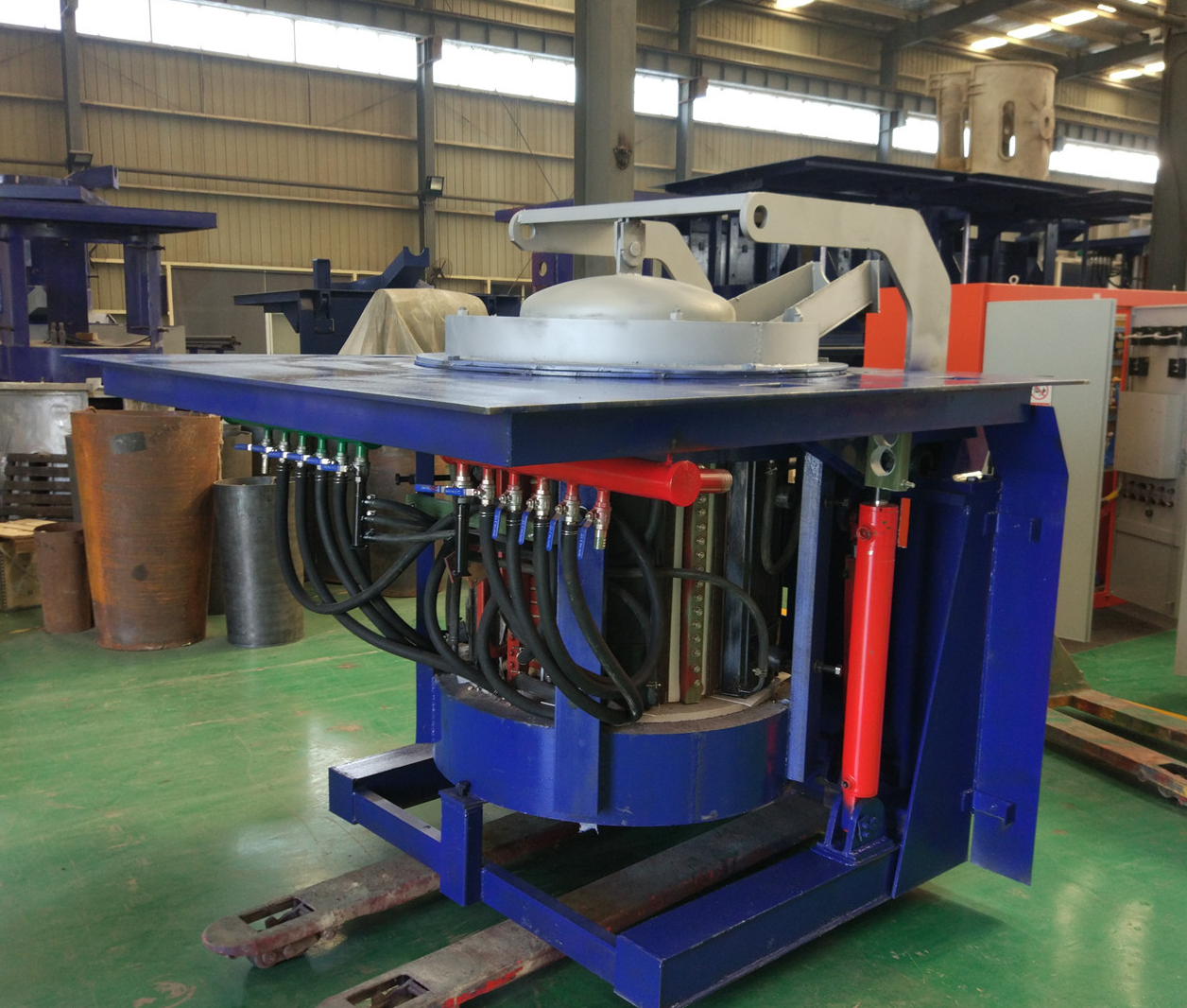
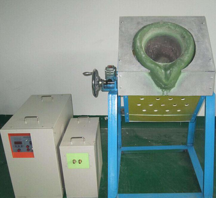
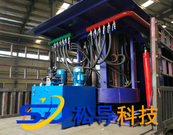
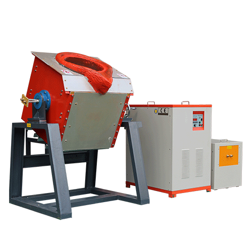
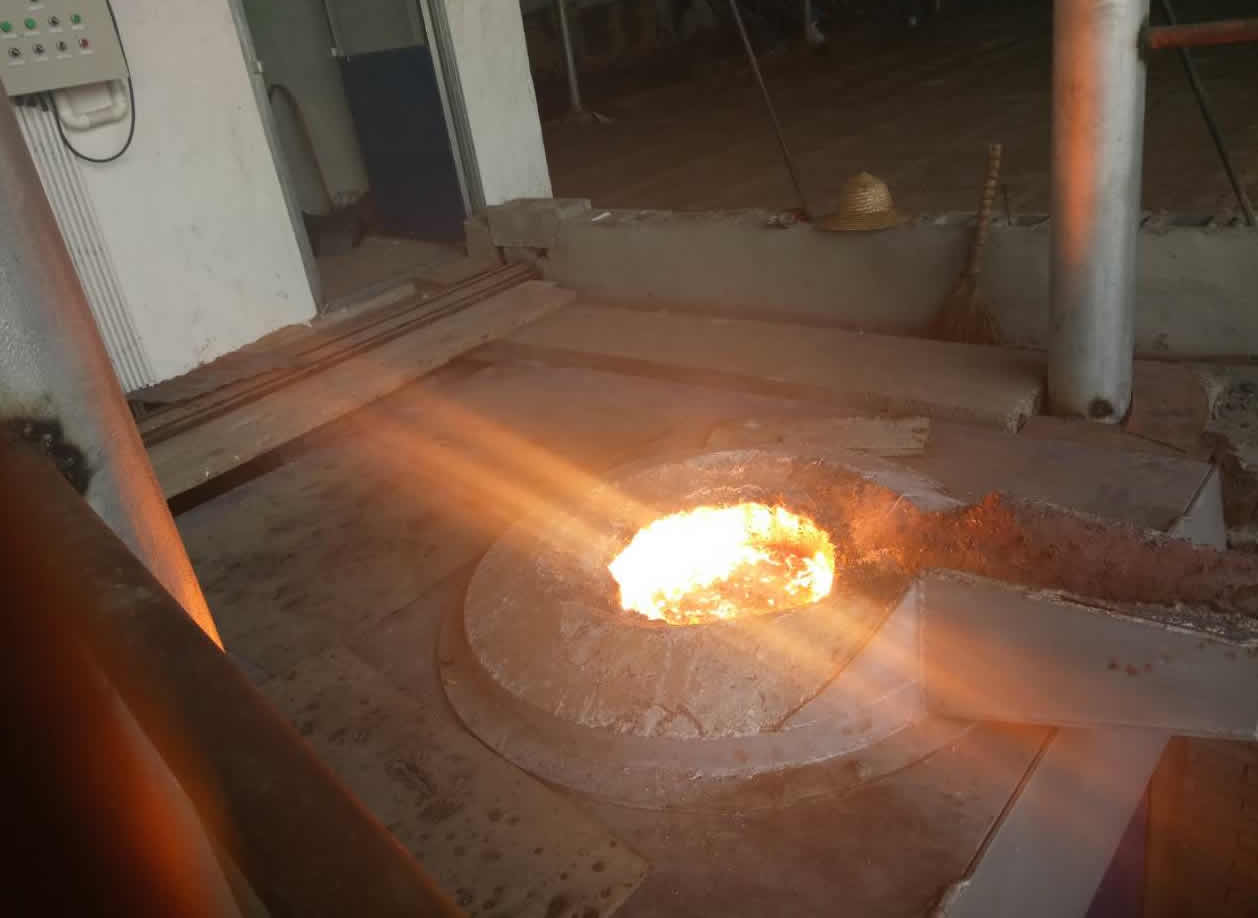
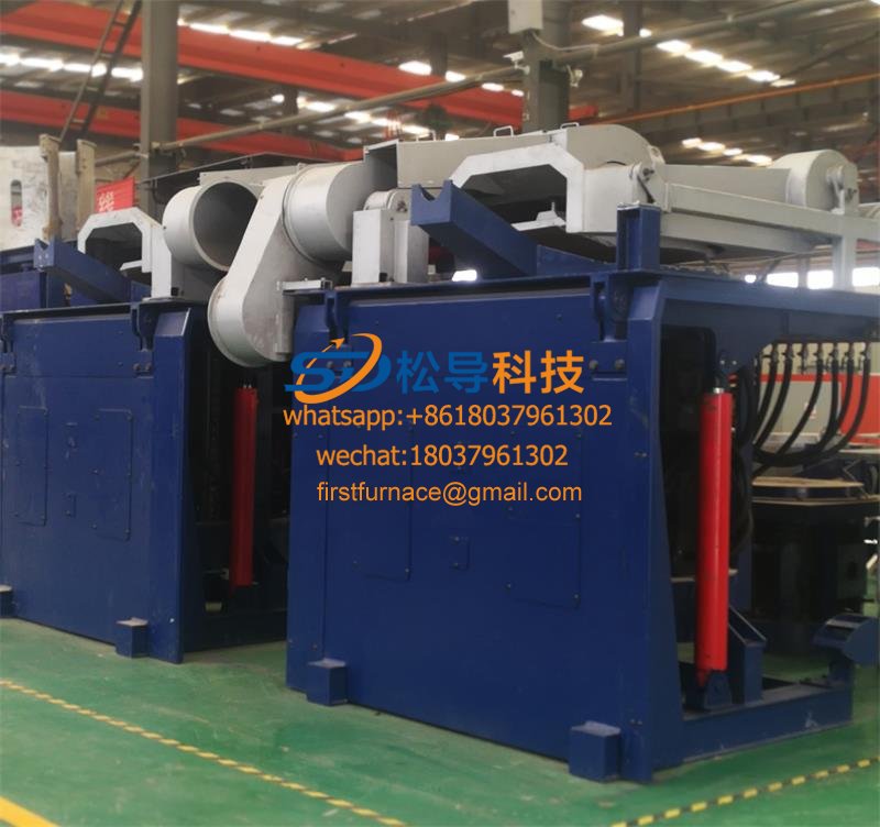
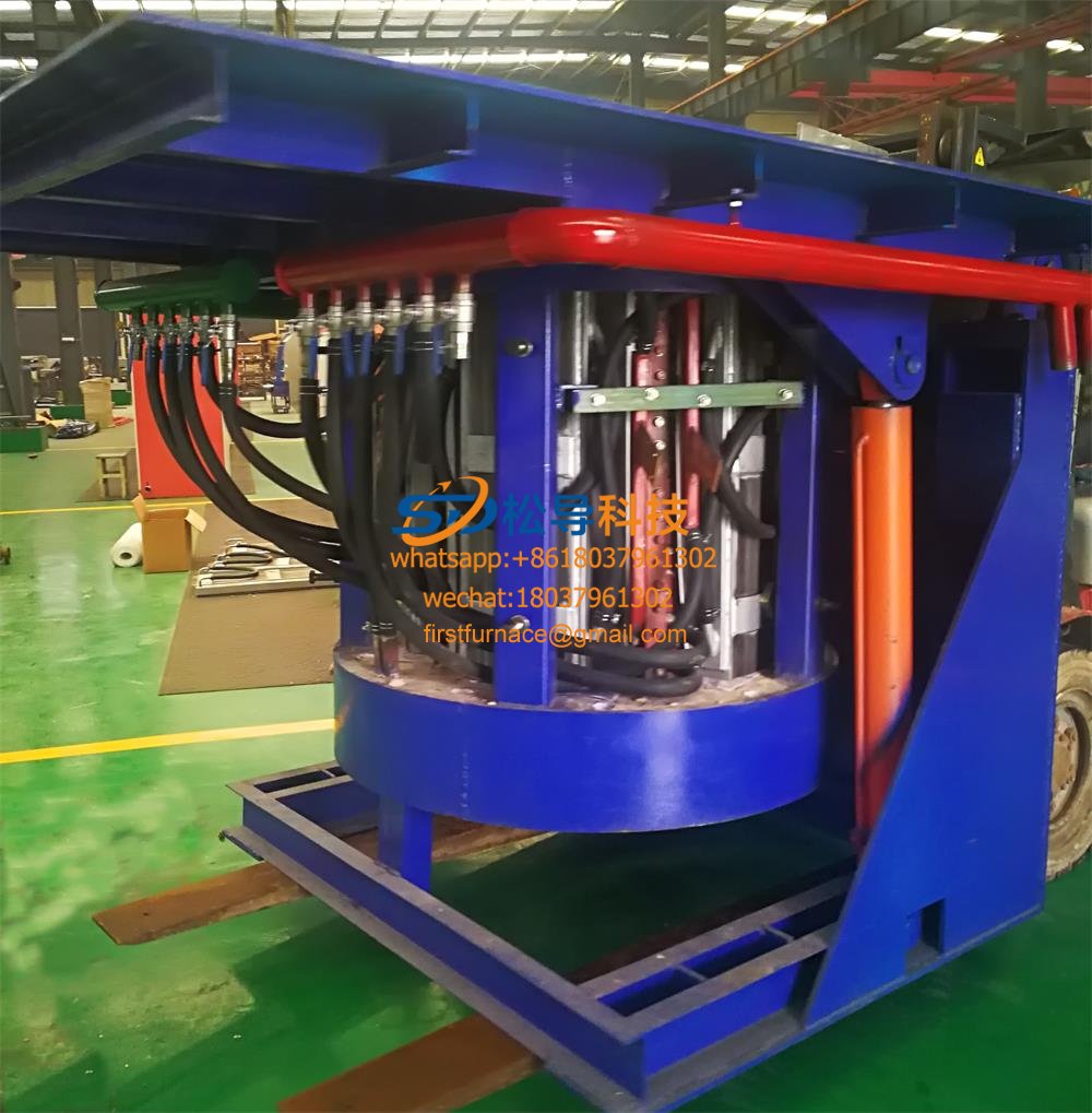
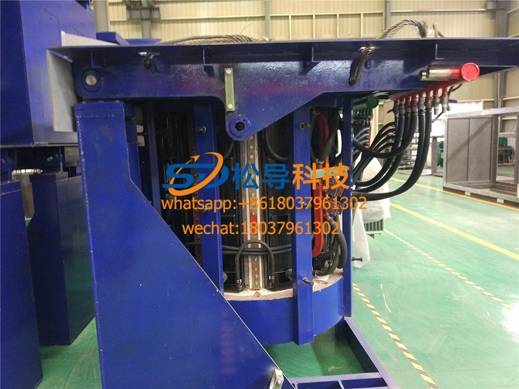
6, the furnace body
The furnace body includes an induction coil, a yoke, a hob, a tilting cylinder and a furnace lid cylinder. Also equipped with furnace lining material, leaking furnace alarm device
6 . 1 induction coil
The induction coil is made of rectangular thick-walled copper tube on a special mold, without joints in the middle, pure copper argon arc welding at both ends, copper tube with high quality cold extruded copper tube with material T2 (99.9%), each group of induction coils There should be no welds inside.
The induction coil is fixed by a series of bolts and insulating stays welded to its outer circumference. The coil is tightened using an adjustable stainless steel screw.
After the coil is fixed, the pitch error of the coil is not more than 2 mm. After 3 times working pressure and water pressure test for 24 hours, it is confirmed that the appearance of the induction coil after no leakage is wrapped with high-strength mica tape for 2 layers, dipped in the insulating paint can for 16 hours, and then dried for 16 hours, so repeated twice to ensure Its insulation grade is H grade, and the withstand voltage is greater than 5000V.
Before the coil is assembled, it will pass the 24 hour working pressure hydraulic pressure test and the 7000V pressure test for 24 hours. After confirming the pass, it can be transferred to the next process.
A stainless steel water cooling ring is arranged on the upper part and the lower part of the induction coil, and the purpose is to make the lining material uniform in the axial direction and prolong the service life of the lining. A Raphael short-circuit ring is arranged on the upper part and the lower part of the induction coil to fully absorb the magnetic leakage at the upper and lower ends to prevent the furnace section from generating heat. The wiring uses side lead wires to reduce the torque of the large cross-section water-cooled cable during the tilting furnace.
On the outer surface of the induction coil, several temperature probe holders are welded in sections according to the water path for mounting the temperature measuring components. The operating temperature of the induction coil can be displayed on the graphic display of the intermediate frequency power supply.
The inner side of the coil is evenly coated with refractory clay with a thickness of 15-25mm (US United Minerals) to ensure good insulation buffer and insulation, convenient for the old furnace lining push and furnace lining to prevent the life of the working lining due to hot and cold deformation.
6 . 2 yoke
The yoke is made of high quality high permeability cold rolled silicon steel sheet. The thickness of the silicon steel sheet is 0.3 mm. The yoke adopts a profiling structure, and the arc of the inner arc surface is the same as the outer arc of the induction coil, so that the yoke can be closely attached to the outer side of the induction coil, maximally restraining the magnetic field radiated outward from the coil, and reducing the magnetic resistance of the outer magnetic circuit. .
The yoke is clamped by stainless steel plates and stainless steel clamps on both sides and fixed by welding. A copper cooling water pipe is welded to the stainless steel plate on both sides for cooling the yoke. The cooling water pipe can withstand 0.45Mpa water pressure and no leakage within 15min.
After the yoke is assembled, the bending degree is not more than 4 mm, and the deviation between the theoretical center line and the actual center line is not more than 3 mm.
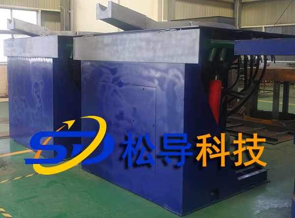
6 . 3 hob
The hob is divided into two parts.
The movable hob is also called a furnace shell for mounting the induction coil and the yoke. It is rolled from a steel plate and is welded with a fully enclosed squirrel-cage frame structure. The operating platform at the top of the movable hob is made of thick steel plate (more than 15m thick) to improve the strength and load-bearing capacity of the hob. The surrounding workbench is made of 6mm pattern steel plate to ensure that it can be flat and not deformed during long-term use, and the noise on the working platform of the furnace is <85dB.
Above the movable hob is the furnace cover. It is hydraulically driven by oil. In order to ensure the reliability of the operation of the furnace cover, its jacking and rotation are driven by two independent cylinders.
The bottom of the movable hob has a fixed flange for connecting the lining quick-release device.
The fixed hob is mounted on the foundation for carrying the movable hob. Upper fixing hob with a hob tilt shaft and associated activities in the furnace tilting pushing cylinder, can turn to lean forward activity hob 95 °. At the bottom of the tilting cylinder, an anti-break speed limit shut-off valve is installed. During the tilting process, if the tubing is broken, the anti-breaking speed limit shut-off valve will act to close the oil return oil passage of the cylinder to stop the electric furnace in place.
The tilting cylinder is in the form of a positive and dustproof sleeve to prevent foreign matter from entering the cylinder.
The hob section is designed with a large safety factor. Ensure that the hob has sufficient rigidity to run smoothly when carrying the maximum load.
6 . 4 Induction coil and charge parameters
The parameters of the induction coil and the charge should be optimized by special computer software to ensure the best electromagnetic coupling efficiency. Considering that the electric furnace needs to be over-loaded, in order to ensure the maximum charge of the electric furnace, the liquid level of the charge does not exceed the upper plane of the water-cooling ring. It is recommended to design the actual capacity according to the nominal capacity of 1.2 to 1.4 times.
The following is a list of the parameters of the electric furnace calculated by computer software optimization design, which is only for practical design reference.
|
Serial number |
project |
parameter |
Remarks |
|
1 |
Average diameter of charge |
1390 |
|
|
2 |
Rated charge height |
1920 |
|
|
3 |
Lining thickness |
160 |
|
In order to extend the service life of the lining, the crucible is designed to be conical. The upper port diameter is larger than the average diameter, and the bottom diameter is slightly smaller than the average diameter.
6 . 5 refractory clay
Refractory cement is a highly insulating and insulating material that is applied to the inside and outside of the induction coil to have the following effects:
Make the induction coil a whole, reducing vibration and noise during operation.
It is applied on the inside and the inside of the induction coil until the top of the pressure block forms a whole body, and the cement which is evenly coated with the inner lining has no obvious convex and concave phenomenon and the axial fastening of the gland bolt, thereby preventing the coil from rising.
The induction coil is protected when the charge leaks.
Conducive to the launch of the lining.
6 . 6, water-cooled cable
The joint of the water-cooled cable is crimped to the copper strand by a cold press forming process. Its single joint and copper wire should be able to withstand more than 8t of tension.
The outer casing of the water-cooled cable is made of a flame-retardant rubber tube that is transferred. This hose is not easy to burn and has good strength. It can withstand 0.45Mpa water pressure without leaking or breaking.
The cable is in the form of a side lead. In order to ensure that the water-cooled cable is taken out from the side of the electric furnace to minimize the length.
The water-cooled cable should be equipped with a circular transition bracket on the furnace body and the rear wall. During the operation of the furnace body, the cables are all arc-transitioned to avoid clogging.
The cable adopts the twisted wire and the copper pipe to be pressed, and the copper sleeve and the stranded wire are formed into a compact whole after being pressed by the cross section, and will not be disengaged under the condition of high frequency vibration or the like. The water-cooled cable outer hose is easy to assemble and disassemble, so that it can be quickly replaced when the hose is aged and damaged.
6 . 7 Pneumatic furnace tools
A set of furnace tools is provided. It includes 1 pneumatic vibrator at the bottom of the furnace, 1 pneumatic vibrator for the furnace wall, 1 pneumatic raft for removing the old lining, 1 smashing plate for the furnace wall, 1 shovel and 1 shovel.
Working pressure: 0.6 Mpa
Hammer frequency: 36 Hz
Exciting force: 1830 N
Impact torque: 8.40 kg•cm
Compressed air consumption: 0.78 M 3 /min
6 . 8 furnace lining quick launch device
The lining quick-release device is used to quickly remove the old lining. It includes a push block, a push cylinder and an operating mechanism. The jacking block is mounted under the lining and is connected to the jacking cylinder through a pushing hole at the bottom of the furnace body. When the old furnace lining needs to be introduced, the electric furnace is tilted to 90 ° , the thrust pin is fixed by the fixing pin and the connecting flange at the bottom of the furnace body, and the old lining is pushed out by operating the manual valve to pressurize the cylinder.
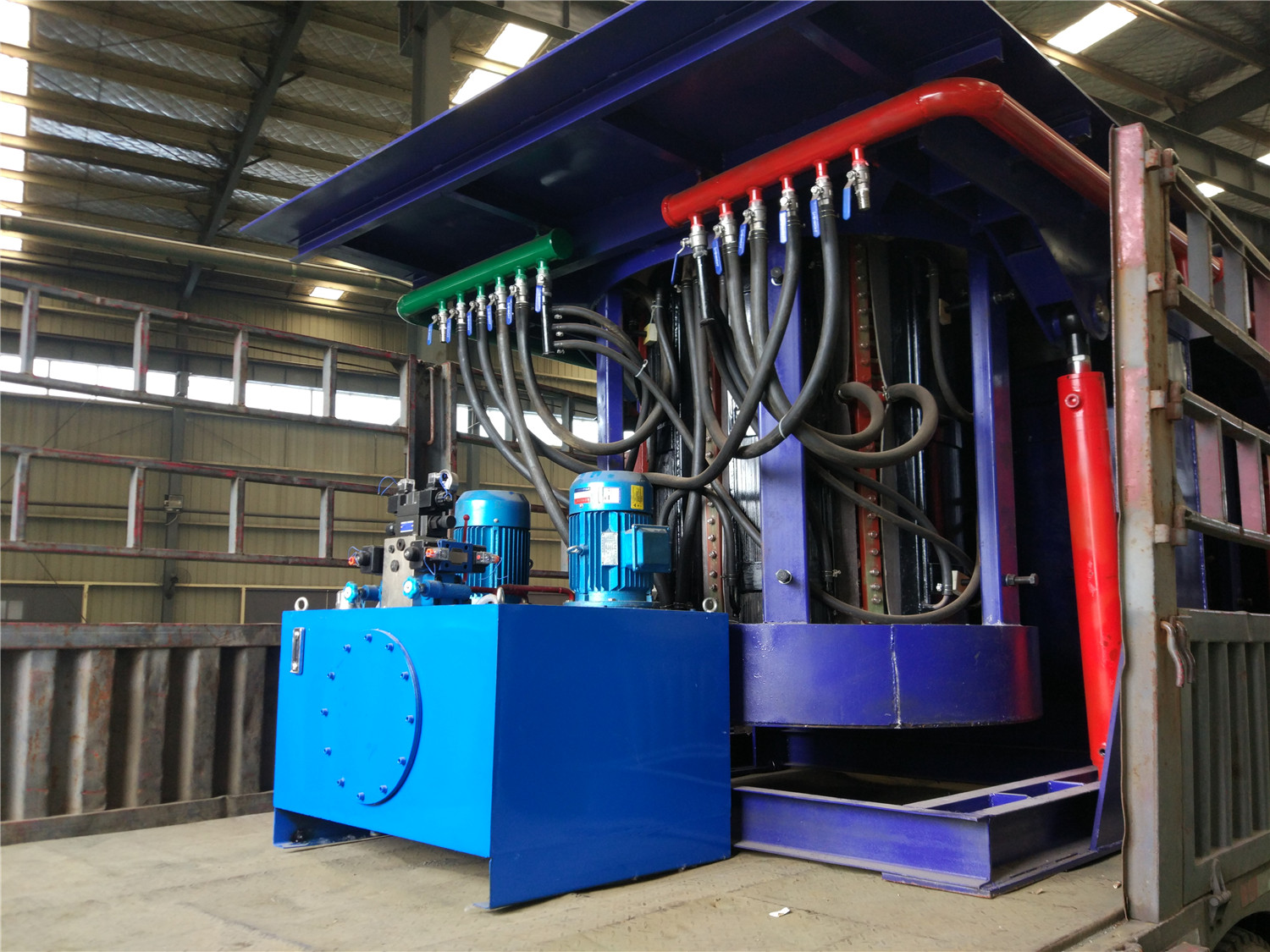
6 . 9 hydraulic system
Includes hydraulic pumping station and tilting station.
The hydraulic pump station is used to power the tilting cylinder, the lid drive cylinder, and the lining push cylinder. The rated working pressure of the pumping station is 11Mpa, and the integrated unit is in the form of double pump and double motor. One set is working normally and the other set is standby. The hydraulic medium is hydraulic oil. The fuel tank structure should be designed reasonably. It adopts a fully enclosed welded structure and has no leakage, ensuring that the maximum oil temperature in summer does not exceed 50 °C. The oil tank is equipped with an oil mark, which can display both the oil level and the oil temperature. The ball valve is installed at the pressure oil outlet for easy pressure regulation. The hydraulic control check valve prevents accidents in the pipe burst. The cylinder rod of the tilting cylinder is equipped with a high temperature resistant protective cover and a flow path control valve.The lifting speed of the cylinder can be adjusted to ensure that the tilting cylinder of the tilting cylinder is synchronously telescopic without jamming, and the furnace body is balanced and balanced.
The tilting table is installed on the stove to control the tilting of the furnace in the range of 0 to 95°, to fall back, the switch of the furnace cover and the lining of the furnace. It is operated by a manual valve with smooth movement and no impact. When the handle is not operated, the entire system can be automatically unloaded even if the pump is in operation. It avoids the defects of oil temperature rise caused by operation errors, high reliability, stable operation and no impact.
The hydraulic station start and stop buttons are installed on the operation platform, and the main power switch and the oil pump running indicator are installed on the side. The manual operation is adopted. The work is reliable and stable, without impact and crawling. The speed is adjustable and can be stopped at any position. .
The furnace cover is hydraulically driven. In order to ensure the reliability of the operation of the furnace cover, its jacking and rotation are driven by two independent cylinders.
All hydraulic components use joint venture manufacturers or domestic quality products. Rexroth components are recommended.
6 . 10 cooling water system
The cooling of the intermediate frequency electric furnace and the intermediate frequency power supply respectively adopt separate independent closed cooling towers. The purpose of using separate cooling devices is to avoid mutual influence. Because the intermediate frequency power supply requires low temperature cooling water, the outlet water temperature should be controlled within 50 ,, but the cooling water temperature of the induction coil of the electric furnace can be slightly higher, which can increase the thermal efficiency of the electric furnace and reduce the volume of the cooling device, thereby reducing the cost.
The core of the fully enclosed cooling unit is a spray-evaporated enclosed cooling tower. There are many heat-dissipating coils inside the cooling tower, and circulating water flows inside the coils without coming into contact with the air. There is a water collecting tray under the cooling tower, and the spraying water is installed inside. The water inlet of the water collecting tray is equipped with a floating ball valve, which can automatically control the water level in the water collecting tray, and the water outlet has a spray water pump. The upper part of the cooling tower is equipped with a water spout and a cooling fan. During operation, the spray pump will pump the water to the upper spout, and the water will be sprayed into the outer surface of the coil, and the cooling fan will simultaneously draw air to vaporize the spray water and take away the heat of the circulating water in the coil.
The fully enclosed cooling water system includes a cooling tower, a water pump, a high water tank, a water storage tank and associated sensors and meters for water temperature, water pressure, and flow detection.
The cooling water system is the basic guarantee for the normal operation of the intermediate frequency power supply and the electric furnace, because the main components of the whole system are water-cooled. Therefore, strict monitoring of the cooling water system is very important. Common faults in the water system include damage to the pump or pump motor, water leakage caused by water leakage from the pump, and rupture of the cooling water hose. In order to be able to detect these faults, we installed a pressure gauge at the inlet of the cooling water system and a temperature sensor on each water-cooled device. The signals from these sensors are sent to the control system, which determines the operation of the cooling water system. These signals are interlocked with the intermediate frequency power supply. When the water system has high water temperature, low water pressure or insufficient water flow, the intermediate frequency power supply will alarm and stop automatically.
Technical parameters of four or three tons of steel shell melting furnace
1 , 12-pulse IF power supply technical parameters
|
Serial number |
project |
parameter |
unit |
Remarks |
|
1 |
Power rating |
2000 |
Kw |
Both smelting and insulation |
|
2 |
Power unidirectional maximum power |
20 00 |
Kw |
Single power supply |
|
3 |
Power input voltage |
950 |
V |
Must be 950v or the current consumes a lot of energy |
|
4 |
Rectifier form |
12 pulse wave |
|
Must be 12 pulses or 6 pulse ripple large noise and large energy consumption. |
|
5 |
Grid side power factor |
>0.9 6 |
|
In any power situation |
|
6 |
Inverter form |
SCR series |
|
Dual-powered 12-pulse IF power supply |
|
7 |
Inverter output frequency |
300- 400 |
Hz |
|
|
8 |
Start success rate |
100% |
|
in any circumstances |
|
9 |
Power conversion efficiency |
0.97 |
|
|
|
10 |
Power consumption |
60 0±5% |
Kwh/t |
Melted from hot normal temperature to 1450 ° C |
2 , induction furnace body
|
Serial number |
project |
parameter |
unit |
Remarks |
|
1 |
Single furnace rated capacity |
3 |
t |
|
|
2 |
Maximum capacity of a single furnace |
3.8 |
t |
|
|
3 |
Rated operating temperature |
1 80 0 |
°C |
|
|
4 |
Lining thickness |
110 |
Mm |
|
|
5 |
Melting material |
Cast iron, cast steel |
|
Hot melt from ordinary temperature to 1 80 0 ℃ |
Iron induction furnace
Aluminum melting furnace
Copper melting furnace
Small steel melting furnace
Small induction melting furnace
Induction iron furnace
3T intermediate frequency iron melting f

0.25T Intermediate Frequency Furnace

0.5T Intermediate Frequency Furnace

Medium Frequency Furnace

2T Induction Melting Furnace

1T Induction Melting Furnace

500kg Induction Melting Furnace

250kg Induction Melting Furnace

Induction Melting Furnace

3 T Induction Melting Furnace

5T Induction Melting Furnace
1T One Belt Two Intermediate Frequency F

5T One Belt Two Intermediate Frequency F
3T One Belt Two Intermediate Frequency F
2T One Belt Two Intermediate Frequency F
5T Parallel Intermediate Frequency Furna

5T Intermediate Frequency Furnace

5T Series Intermediate Frequency Furnace
3T Series Intermediate Frequency Furnace
2T Series Intermediate Frequency Furnace
1T Series Intermediate Frequency Furnace
0.5T Series Intermediate Frequency Furna

0.25T Series Intermediate Frequency Furn
1T Parallel Intermediate Frequency Furna
2T Parallel Intermediate Frequency Furna
0.5T Parallel Intermediate Frequency Fur