Sales hot line ( 24 hours service): 18037961302
E-Mail: firstfurnace@gmail.com
whatsapp:+8618037961302
Adress: Luoxin Industrial Park, Luoyang, HenanLarge diameter steel pipe quen
Piston rod quenching and tempe
Grinding rod quenching and tem
High frequency induction heate
Quenching equipment for machin
Round steel end heating furnac
Steel pipe heat treatment prod
Square steel quenching and tem
Sucker rod quenching and tempe
Thickened petroleum steel pipe
Round steel quenching and temp
Steel pipe quenching and tempe
Steel plate quenching and temp
Induction Hardening Machine&nb
Flywheel ring gear high freque
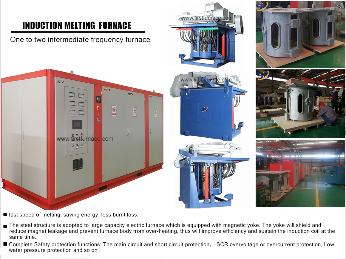
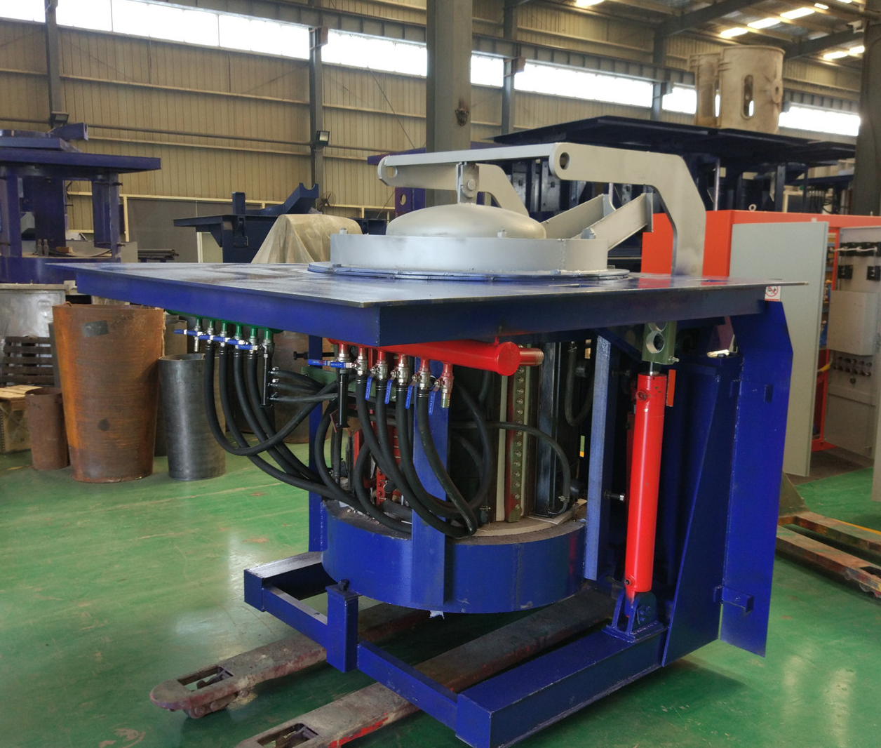
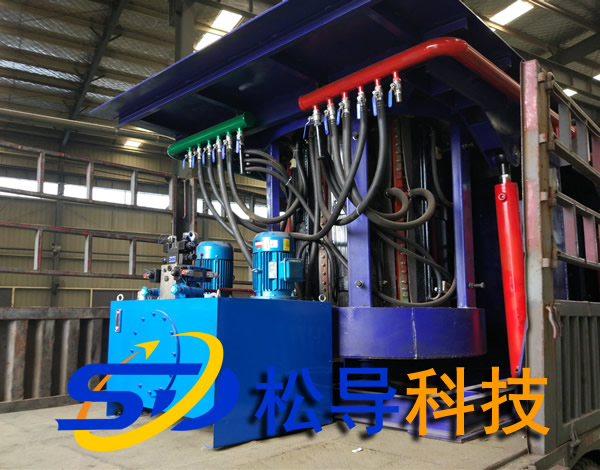
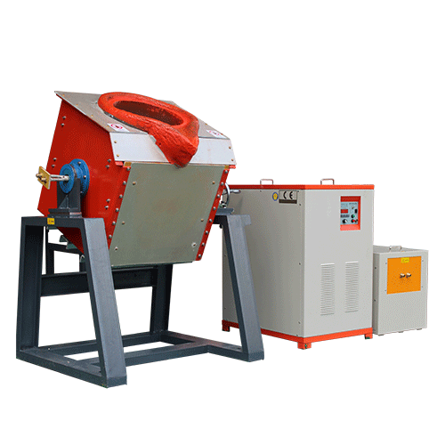
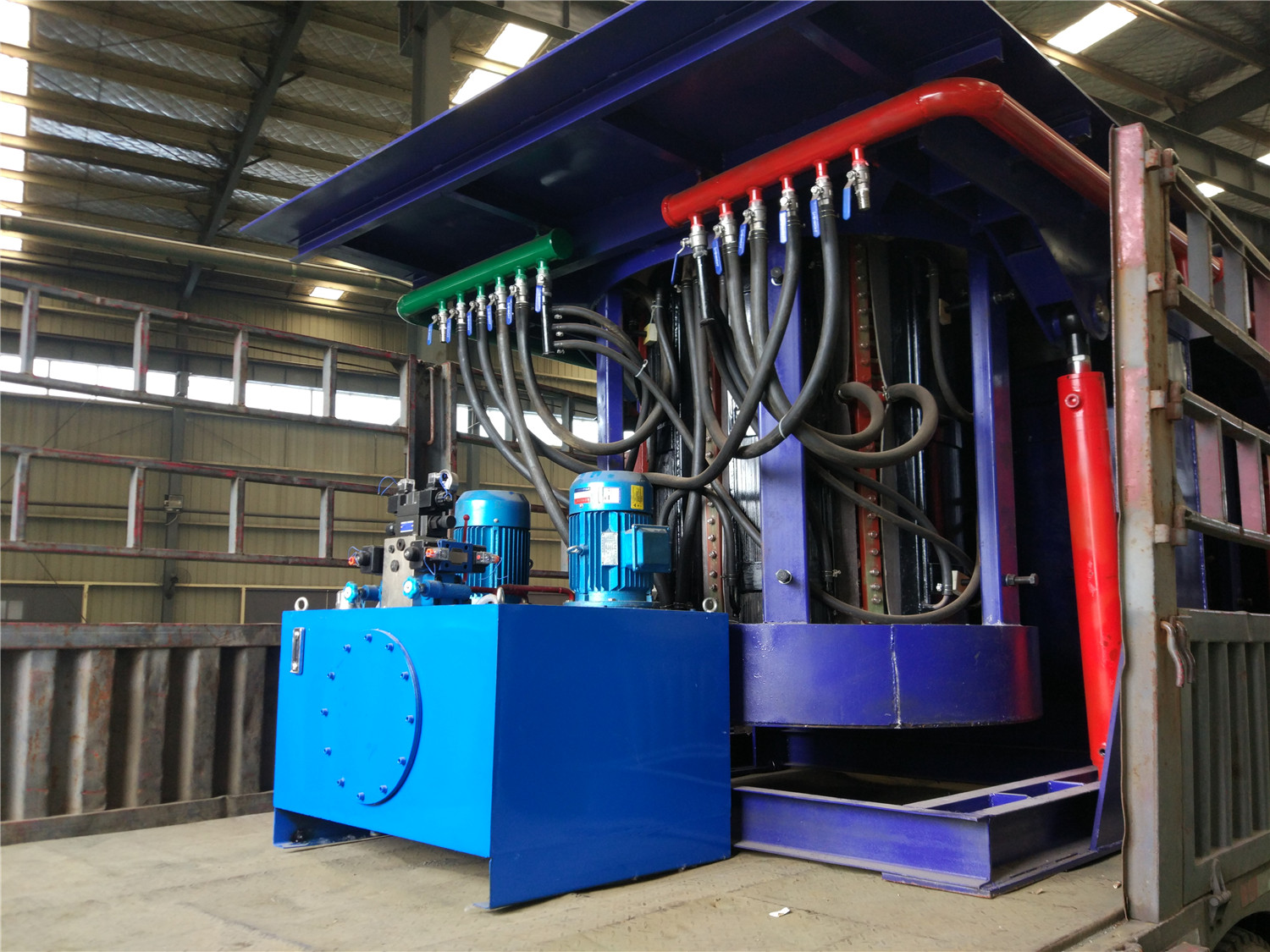
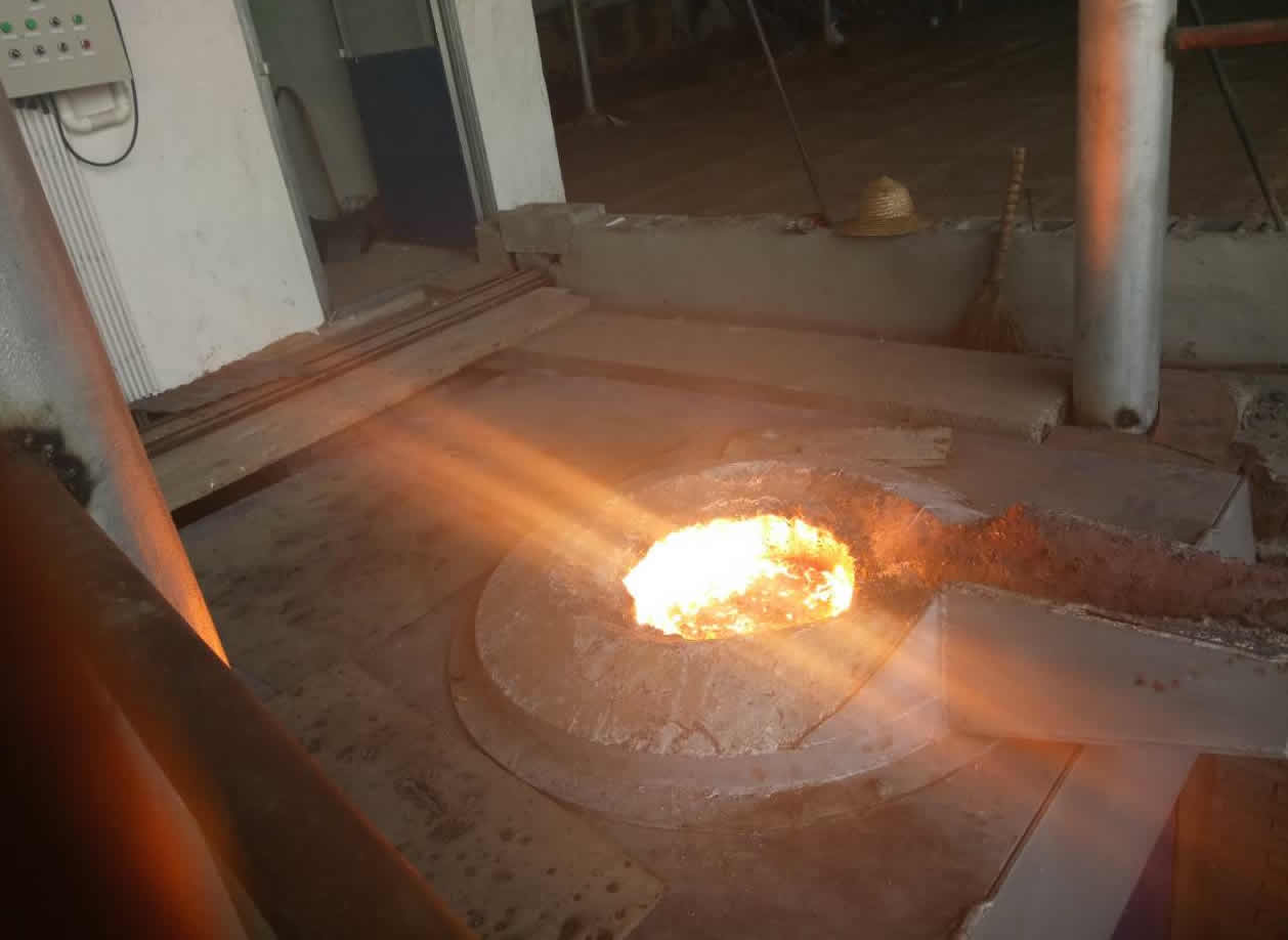
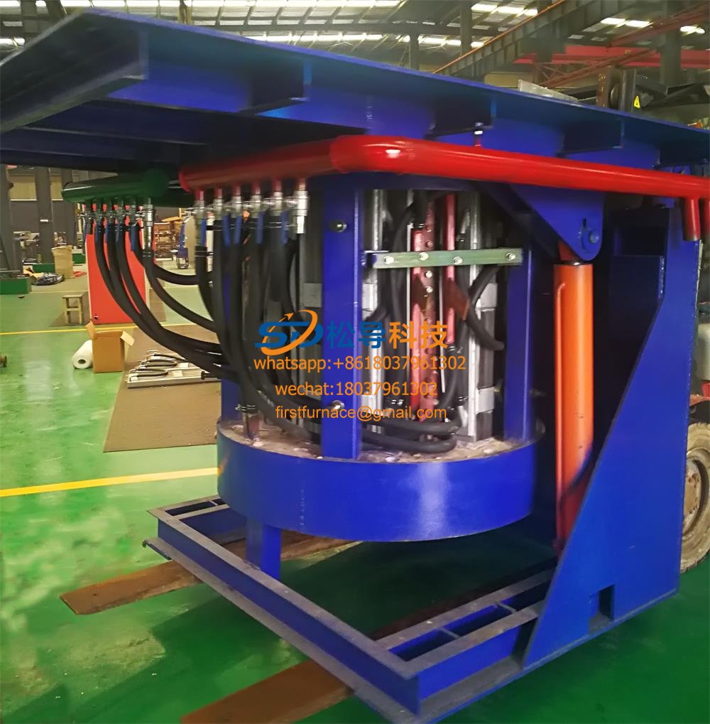
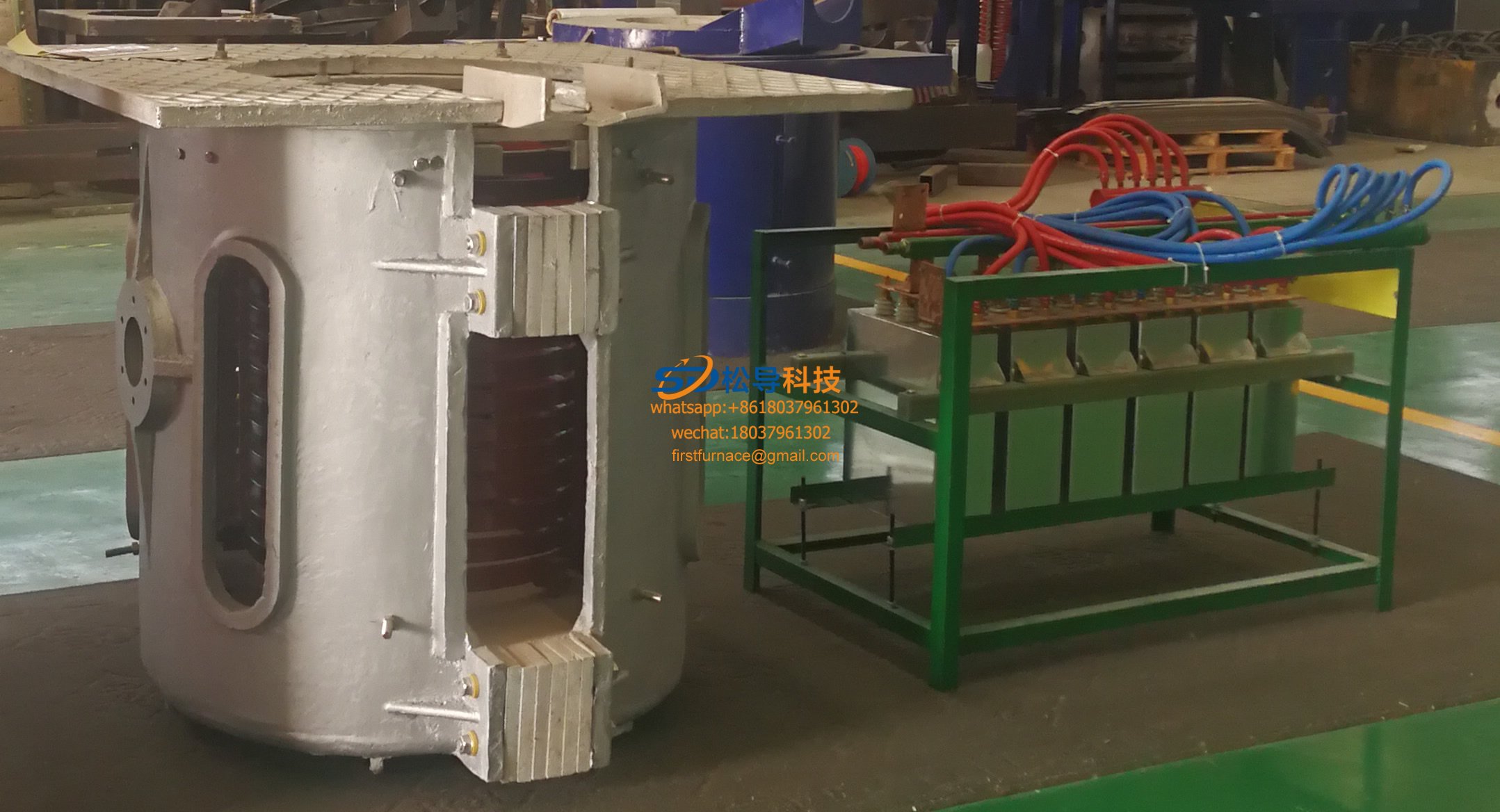
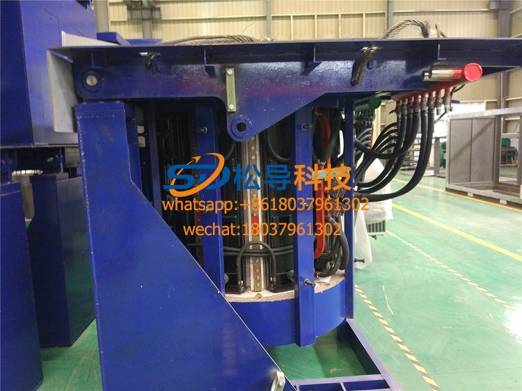
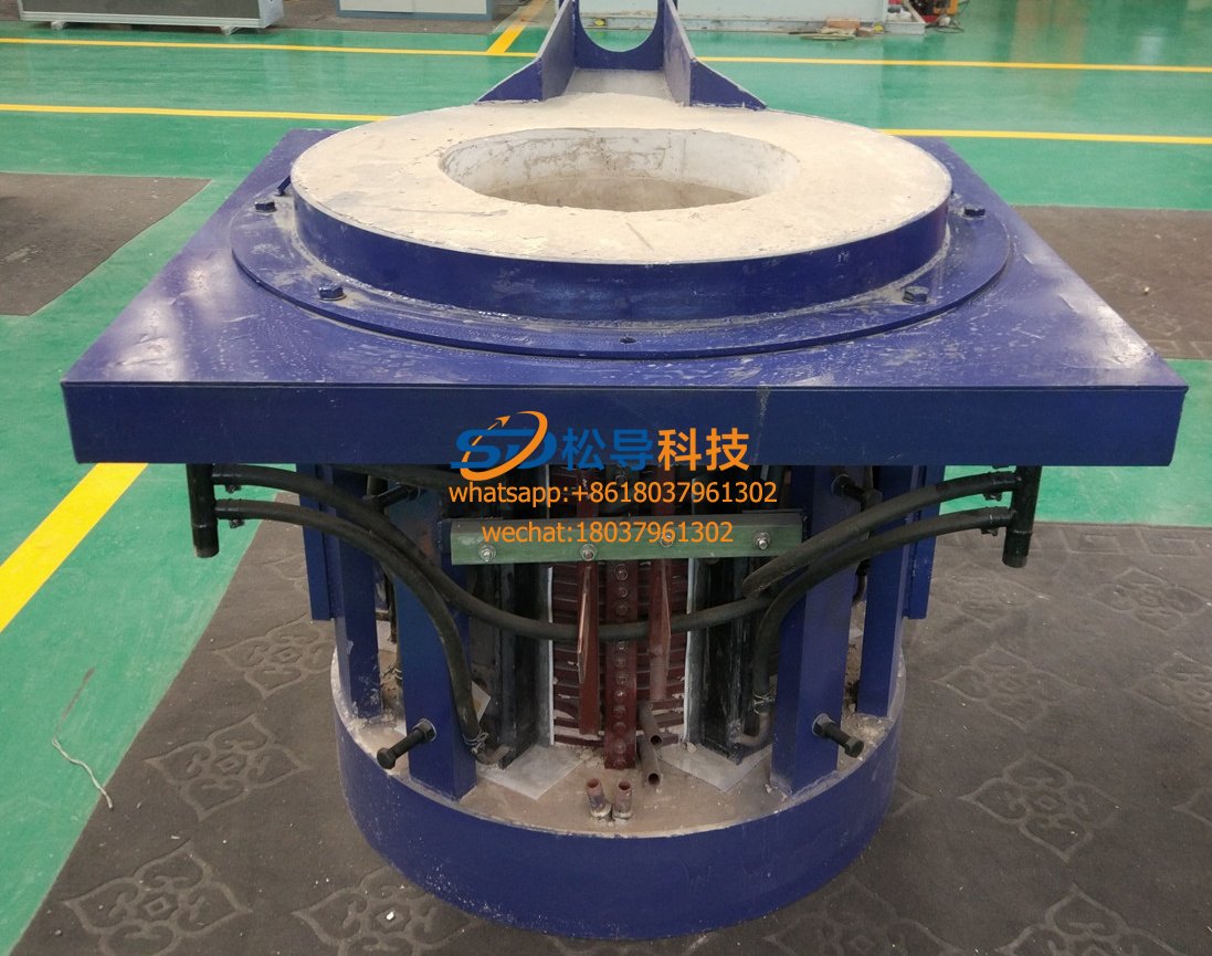
1 ton induction melting furnace detection and debugging method
1. Detect after turning on the control power
Close the "2P circuit breaker" and "control switch", turn on the main power switch, do not start the main circuit, and only turn on the relay control circuit. Check the operation sequence of each relay, check the time relay operation time, and whether each indicator light is normal.
First observe whether the indicator value on the control panel of the new 1 ton induction melting furnace is normal (such as rectification control voltmeter 30V, rectification pulse current meter 130-150mA, inverter control voltmeter 12V, inverter pulse current meter 100~120mA), if the value is Within the normal range, there is no problem with the 1 ton induction melting furnace section.
Place the change-over switch SA in the check block, check the waveform of the rectification and inverter trigger pulses with an oscilloscope, and check if the amplitude and time interval are normal. The rectification trigger pulse is a double pulse, and the time interval is 3.33 ms; the inverter trigger pulse is a continuous pulse train, and the amplitude is generally 4-6 Vo, and the pulse is neat and burr-free. The order of inspection is from the thyristor control pole to the pulse transformer and then to the rectifier and inverter boards.
2.1 tons of induction melting furnace rectification part detection
1) 1 ton induction melting furnace main circuit detection
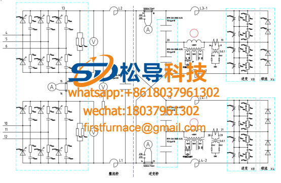
The rectifier usually uses a three-phase full-control bridge rectifier circuit, which includes six fast-acting fuses, six thyristors, six pulse transformers, and one freewheeling diode. There is a red indicator on the quick-blow fuse, which normally shrinks inside the housing and pops up when the fast-blow fuse blows. Some fast-blow indicators have a tight indicator. When the fast-blow fuse blows, it will get stuck inside. Therefore, for the sake of reliability, you can use the multimeter's on-off block to measure the quick-blow fuse to judge the fuse of the quick-blow fuse. Whether the body is blown.
A simple method of detecting the thyristor is to measure the thyristor cathode-anode resistance and the gate-resistance of the thyristor with a ohmmeter of the multimeter. The thyristor does not need to be taken off during the measurement. Under normal circumstances, the anode-cathode resistance should be infinite, and the gate-resistance of the control pole should be 10-50Ω. If it is too large or too small, it indicates that the thyristor control is likely to fail and it will not be triggered to conduct.
When it is suspected that the 1 ton induction melting furnace rectifier failure causes the 1 ton induction melting furnace to be unable to work normally, it should be tested as follows in the case of power failure: First, the system must pass water to disconnect the main circuit from the pre-stage of the filter reactor. On, the three-phase full-wave rectified two output terminals are connected with a resistive load with a resistance greater than or equal to 500Ω and a power of 500W or more (commonly used in two or four 150W incandescent lamps in series). After power on, the DC voltmeter should be able to indicate a position of approximately 1.35 × U1 (U is the AC input line voltage).
2) 1 ton induction melting furnace control and trigger circuit detection
(l) Proofreading phase sequence, the phase sequence of the three-phase incoming lines U, V, W is required to coincide with the U, V, W phase sequence of the secondary side of the synchronous transformer.
(2) Turn on the control power, the article source: http://www.minglusc.com/BdwlkjNews.asp?id=866 check whether the output voltage is normal. If a voltage does not match, check for any adjustments. If the adjustment does not work or there is no adjustment, it may be that the components on the rectifier voltage regulator board are damaged, or the load short circuit may cause the power supply output voltage to decrease, which can be eliminated by further inspection.
(3) Check if the 1 ton induction melting furnace rectifier plate is normal. Unplug the inverter board, place the switch in the inspection block, press the start button, turn the power adjustment potentiometer to see if the DC voltage can be adjusted to about 500V. If the voltage can be adjusted to 500V, the rectifier board is normal.
(4) The rectifier thyristor trigger pulse check items and methods are as follows.
1 Check whether the output of each trigger board and the gate wiring of each thyristor (VT1~VT6) match the drawing. The pulse transformer is connected to the thyristor, the primary is connected to the main control board, and the primary resistance is about 50Ω measured by a multimeter. The freewheeling diode is generally not prone to failure. When checking, the multimeter diode is used to block both ends. When the multimeter is in the forward direction, the junction voltage drop is about 500mV, and the reverse is not possible.
2 Check whether the trigger pulse phase shift meets the requirements, otherwise the trigger circuit needs to be adjusted. Use a dual-track oscilloscope to sequentially check whether the trigger pulses of each thyristor (VT1~VT6) differ by 600° in the specified order.
3 The trigger pulse must be a positive pulse, otherwise the thyristor cannot be triggered. The trigger pulse is required to have a certain width and reach a certain power. The threshold voltage and current required for the thyristors of different capacities are different and can be checked according to the instructions.
4 Check the pulse blocking protection action, the copyright of the article belongs to: http://www.minglusc.com. Overcurrent or overvoltage occurs when all inverter circuits fail. The detection circuit detects the overcurrent or overvoltage signal, and moves the phase of the 6-way rectification trigger pulse to a=150° through the protection control circuit. The three-phase bridge type full control rectifier circuit is switched from the rectified working state to the inverting working state. The rectifier circuit no longer outputs energy, but instead feeds the energy of the load end back to the power grid, thereby preventing the accident from further expanding and protecting. The method of checking the pulse blocking protection action is as follows: The main circuit of the 1 ton induction melting furnace is not closed, press the inverter working button. Adjust the firing angle potentiometer RP to move the pulse front to a = 0°. Then use the method of adding a regulated power supply (the voltage is determined according to the actual circuit condition) to simulate the overcurrent signal. Instantly add the regulated power supply to both ends of the overcurrent and overvoltage detection bridge rectifier (note that the polarity of the regulated power supply is the same as the polarity of the rectifier bridge). At this time, the trigger pulse should be at a=150° position. Otherwise The circuit should be inspected or adjusted.
(5) Check the capacitor charging circuit in the starting circuit, unplug the inverter board, and place the conversion switch in the inspection block. Press the start button and measure the voltage across the capacitor Cr with a multimeter. If it can reach 500V, it will prove that the starting capacitor is charged. The loop is normal.
(6) Check the magnetizing resistor for open circuit and low-pass filter for open circuit.
Iron induction furnace
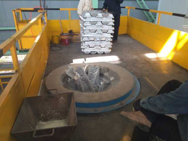
Aluminum melting furnace
Copper melting furnace
Small steel melting furnace
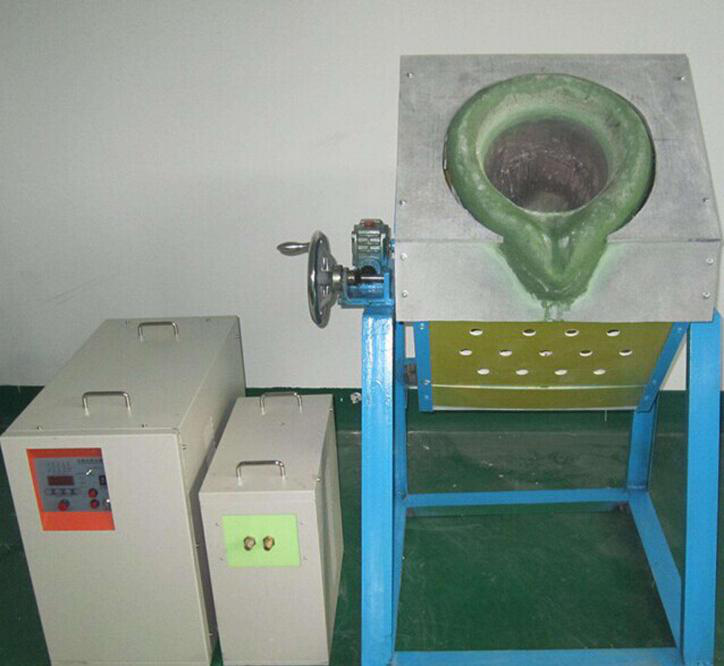
Small induction melting furnace
Induction iron furnace
3T intermediate frequency iron melting f

0.25T Intermediate Frequency Furnace

0.5T Intermediate Frequency Furnace

Medium Frequency Furnace

2T Induction Melting Furnace

1T Induction Melting Furnace

500kg Induction Melting Furnace

250kg Induction Melting Furnace

Induction Melting Furnace

3 T Induction Melting Furnace

5T Induction Melting Furnace
1T One Belt Two Intermediate Frequency F

5T One Belt Two Intermediate Frequency F
3T One Belt Two Intermediate Frequency F
2T One Belt Two Intermediate Frequency F
5T Parallel Intermediate Frequency Furna

5T Intermediate Frequency Furnace

5T Series Intermediate Frequency Furnace
3T Series Intermediate Frequency Furnace
2T Series Intermediate Frequency Furnace
1T Series Intermediate Frequency Furnace
0.5T Series Intermediate Frequency Furna

0.25T Series Intermediate Frequency Furn
1T Parallel Intermediate Frequency Furna
2T Parallel Intermediate Frequency Furna
0.5T Parallel Intermediate Frequency Fur