Sales hot line ( 24 hours service): 18037961302
E-Mail: firstfurnace@gmail.com
whatsapp:+8618037961302
Adress: Luoxin Industrial Park, Luoyang, HenanLarge diameter steel pipe quen
Piston rod quenching and tempe
Grinding rod quenching and tem
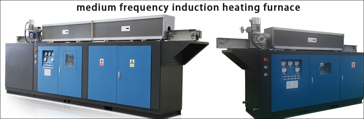
High frequency induction heate
Quenching equipment for machin
Round steel end heating furnac
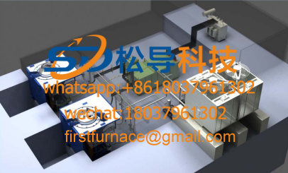
Steel pipe heat treatment prod
Square steel quenching and tem
Sucker rod quenching and tempe
Thickened petroleum steel pipe
Round steel quenching and temp
Steel pipe quenching and tempe
Steel plate quenching and temp
Induction Hardening Machine&nb
Flywheel ring gear high freque
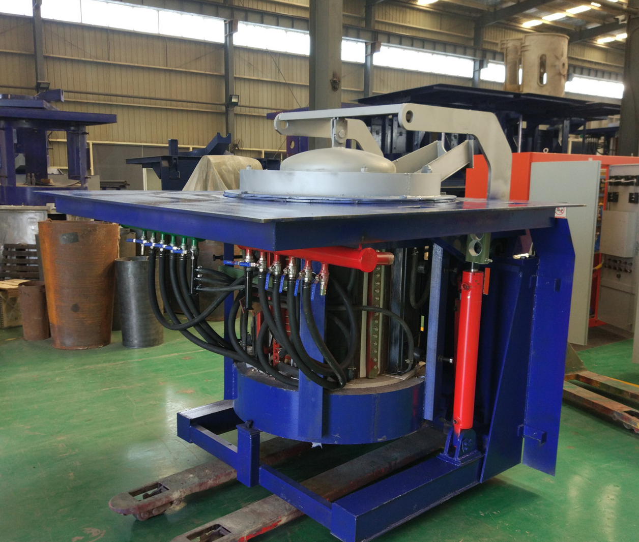
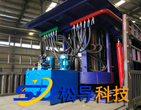
Principle of PLC operating condition monitoring system for intermediate frequency furnace
The system uses Siemens PLC hardware and a 10-inch display combination, with controllable adjustable, automatic display, automatic memory and other functions.
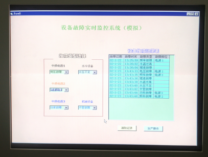
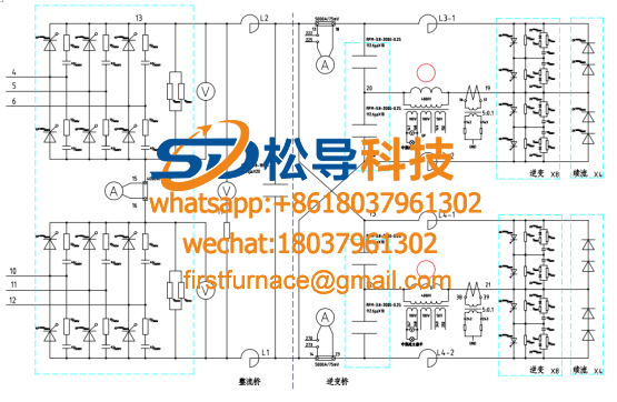
1, equipment PLC external control console is equipped with DC voltmeter, DC current meter, intermediate frequency voltmeter, intermediate frequency meter, intermediate frequency power meter, temperature display instrument. All device parameters are visually displayed. Siemens 10-inch touch screen can easily set the oven or melting process, and can display parameter curves such as melting temperature and equipment power in real time. The console is designed with control power switch, medium frequency manual and automatic switch, emergency stop button, power indicator, medium frequency indicator and fault indication warning light.
2, IF power control board is designed with temperature closed-loop control interface, temperature control instrument selects Japan Island Power SR3 with PID adjustment instrument, far-infrared fiber optic thermometer selects Germany Opus CT series copper measurement special thermometer, measuring temperature -40 -900 ° C. Firstly, the heating temperature and annealing speed are set in the temperature control instrument or PLC touch screen. After the power is turned on, the thermometer measures the heating temperature in real time and feeds back to the temperature control instrument. The temperature control meter compares the measured temperature with the set heating temperature and then outputs the simulation. The signal is sent to the intermediate frequency main control board, and the main control board automatically adjusts the thyristor firing angle according to the level of the signal, so that the power output power is adjusted according to the level of the analog signal, and the temperature closed loop control is achieved. When the copper tube feed speed is adjusted, the thermometer detects the temperature change of the copper tube, and outputs a corresponding current signal according to the comparison between the detected temperature and the set temperature.
For the IF control board, the output power of the IF power supply is adjusted to the required power to achieve the purpose of temperature closed loop control.
CT series Opus copper measuring special thermometer
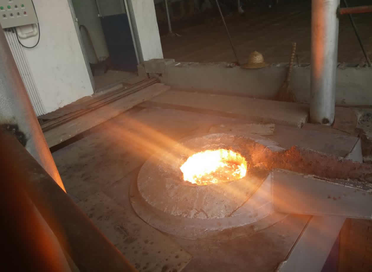
3. The external control console IF switch is designed with manual and automatic operation knobs. When the automatic mode is selected, the device selects the temperature closed-loop control system, and the device power automatically adjusts the output power according to the set melting temperature. The IF power control board is designed with a temperature closed-loop control interface. The temperature-controlled instrument uses the Japan Island Power SR3 with a PID adjustment meter. The far-infrared fiber temperature meter uses the German Opus CT series dedicated thermometer to measure the temperature at 385-1600 °C. Firstly, the melting temperature is set in the temperature control instrument or the PLC touch screen. After the intermediate frequency power supply is started, the temperature meter measures the temperature in real time and feeds back to the temperature control instrument. The temperature control meter compares the measured temperature with the set heating temperature and outputs an analog signal to the temperature control instrument. The intermediate frequency main control board automatically adjusts the thyristor firing angle according to the level of the signal, so that the power output power is adjusted according to the level of the analog signal. When the user selects the manual mode of operation, the device melts at the maximum output power.
4, in addition to displaying the operating conditions of the device, the touch screen can also monitor the device fault and have information such as maintenance tips. The operation guide is accompanied by equipment operating procedures, common fault phenomena and treatment methods.
The IF power PLC equipment health monitoring system can have the following functions:
1) Perfect melting control management function, automatic fault diagnosis, automatic furnace lining sintering and other functions. 2) 2) Perfect melting process control function and perfect monitoring, alarm and fault self-diagnosis function. 3) 3) Perfect sound and light alarm system, alarming the following conditions:
The frequency conversion cabinet is turned on;
Capacitor damage;
The temperature of each cooling water of the power supply is too high;
The power supply cooling water pressure is too low;
The temperature of the furnace cooling water is too high;
The furnace cooling water pressure is too low;
Furnace selection/isolation switch error;
There is no DC output in the rectification part of the variable frequency power supply;
Ground/leakage detection alarm.
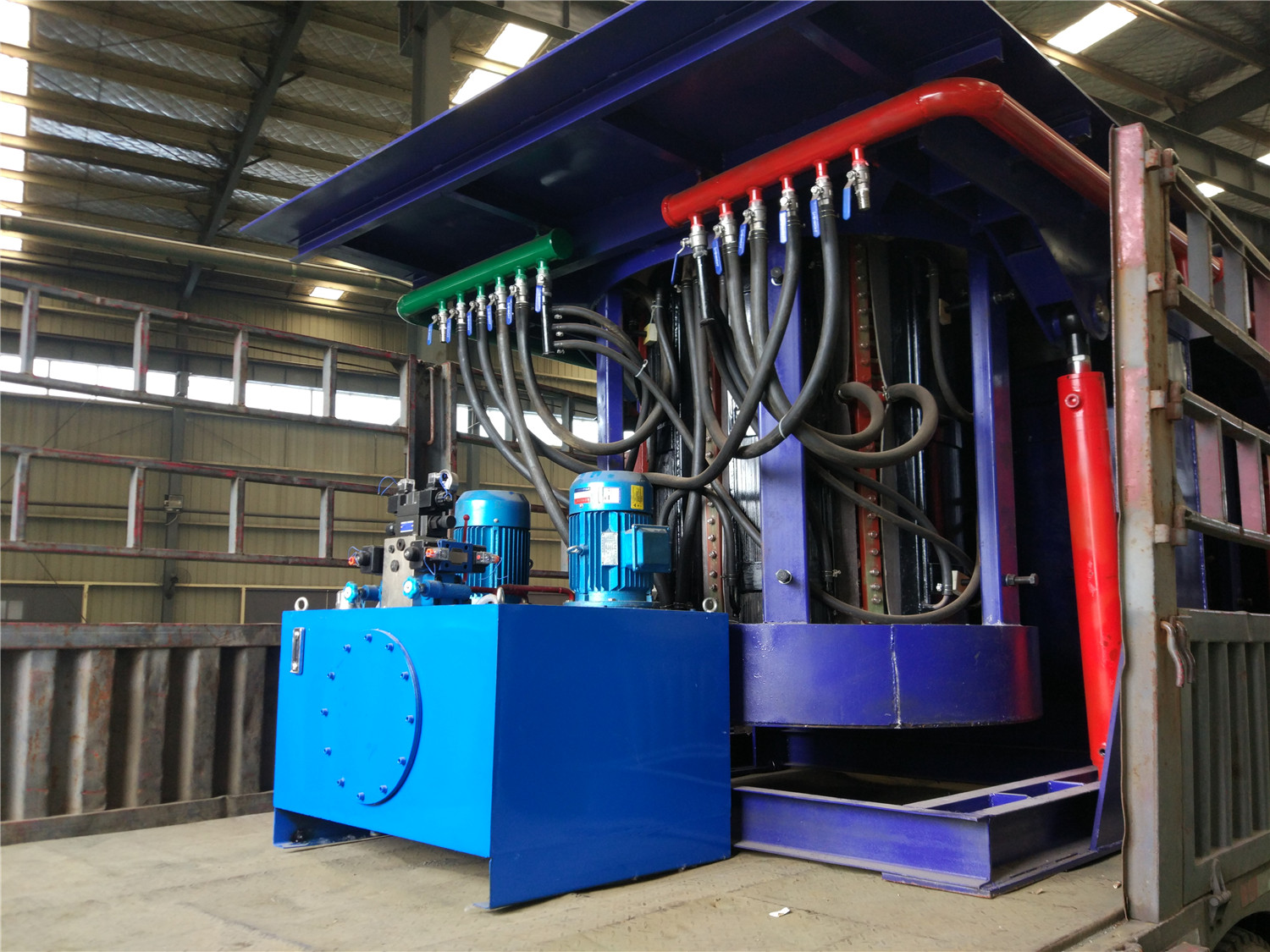
Control cabinet and power distribution installation wiring technology:
Main switch: The incoming six-wire eight-wire system, that is, the six-phase power supply, the one-phase ground wire, and the one-phase neutral wire are fixed by the wiring nose. The switch specification capacity is less than the load of the sub-switch and equipment. The main switch is remote from the DC24V power supply. The main line uses AC380V or AC220V, and the control circuit uses DC24V.
The ground wire row and the zero wire row are respectively marked and fixed, and the control cabinet door is designed with a cross-grounding wire.
The control cabinet door is marked with the indication of each branch switch control.
The control cabinet is designed with ventilation (the axial flow fan and the inlet grille form convection), and the air exchange port has a dust filter net.
The lighting inside the control cabinet is intact, to ensure that the door is lit, or to install a switch to control the lighting.
All line routing specifications are incorporated into the trunking, and the line numbers are marked. The line number does not fade, and it matches the drawing. The wire diameter is selected appropriately, and the infrared thermometer checks that there is no overheating or overloading on each line.
Large exposed switch wiring, copper busbars, etc. are equipped with insulating protective plates and anti-rat boards.
A rubber pad that meets safety requirements such as insulation grade and size is placed in front of the control cabinet.
For motor control mode: control system with air switch + contactor + thermal relay or motor protection switch + contactor.
Fixing method: The electrical components are fixed on the control cabinet with 35mm standard rails.
Wiring method: Fix and mark the line number with the terminal;
PLC part: PLC power supply has corresponding protection facilities; PLC is installed firmly and well ventilated; input and output are distinguished by two lines; there are more than 5 I/O points for standby.
Inverter part: The capacity is 1 level higher than the rated power of the motor; the incoming line has a reasonable protection system;
Multi-core cord wiring trough is used in the cabinet; 220V, DC24V line color is separated; the wire has a spare space in the slot; the outlet of the distribution wire is protected with rubber; the wire has a standard wire number.
Terminal block part: The terminal is installed at the lower end of the control cabinet, 380V, DC24V are installed separately; the power distribution cabinet and peripheral equipment are connected by aviation plug or terminal block.
External wire trough, specification, safety, pressure resistance, no deformation.
The cable and wire in the production line are routed in the trench, and the distribution with water and gas path is reasonable.
The connection line number of the input and output parts of the device is clear, durable, and easy to find on site; it will not be lost due to replacement of parts;
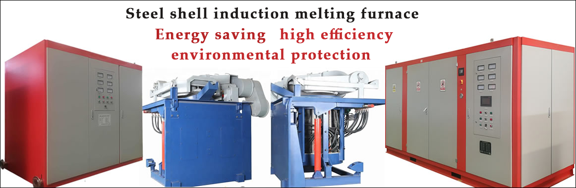
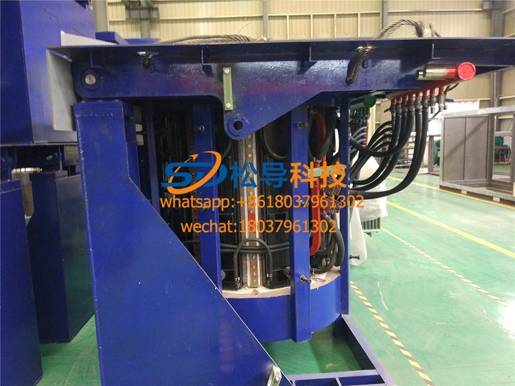
Iron induction furnace
Aluminum melting furnace
Copper melting furnace
Small steel melting furnace
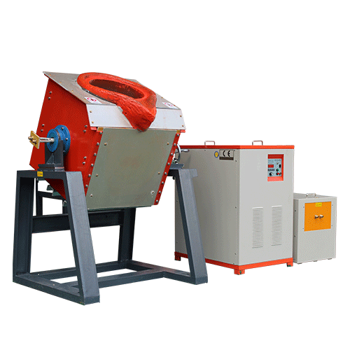
Small induction melting furnace
Induction iron furnace
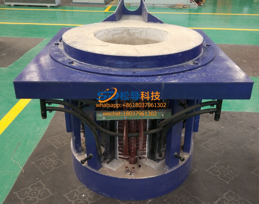
3T intermediate frequency iron melting f

0.25T Intermediate Frequency Furnace

0.5T Intermediate Frequency Furnace

Medium Frequency Furnace

2T Induction Melting Furnace

1T Induction Melting Furnace

500kg Induction Melting Furnace

250kg Induction Melting Furnace

Induction Melting Furnace

3 T Induction Melting Furnace

5T Induction Melting Furnace
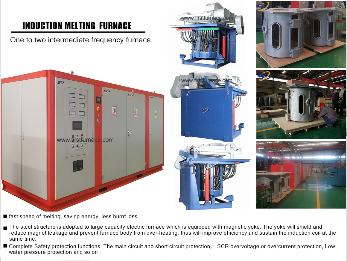
1T One Belt Two Intermediate Frequency F

5T One Belt Two Intermediate Frequency F
3T One Belt Two Intermediate Frequency F
2T One Belt Two Intermediate Frequency F
5T Parallel Intermediate Frequency Furna

5T Intermediate Frequency Furnace

5T Series Intermediate Frequency Furnace
3T Series Intermediate Frequency Furnace
2T Series Intermediate Frequency Furnace
1T Series Intermediate Frequency Furnace
0.5T Series Intermediate Frequency Furna

0.25T Series Intermediate Frequency Furn
1T Parallel Intermediate Frequency Furna
2T Parallel Intermediate Frequency Furna
0.5T Parallel Intermediate Frequency Fur