Contact
Tel: 18037961302
Sales hot line ( 24 hours service): 18037961302
Sales hot line ( 24 hours service): 18037961302
E-Mail: firstfurnace@gmail.com
whatsapp:+8618037961302
Adress: Luoxin Industrial Park, Luoyang, HenanLarge diameter steel pipe quen
Piston rod quenching and tempe
Grinding rod quenching and tem
High frequency induction heate
Quenching equipment for machin
Round steel end heating furnac
Steel pipe heat treatment prod
Square steel quenching and tem
Sucker rod quenching and tempe
Thickened petroleum steel pipe
Round steel quenching and temp
Steel pipe quenching and tempe
Steel plate quenching and temp
Induction Hardening Machine&nb
Flywheel ring gear high freque
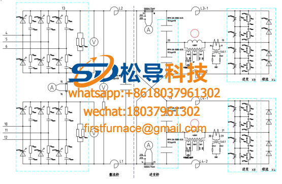
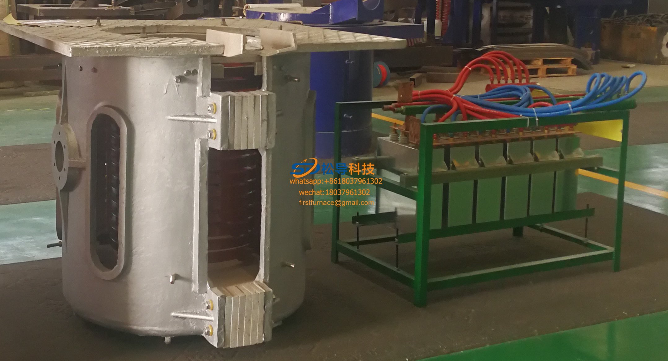
Electric furnace principle(原理)
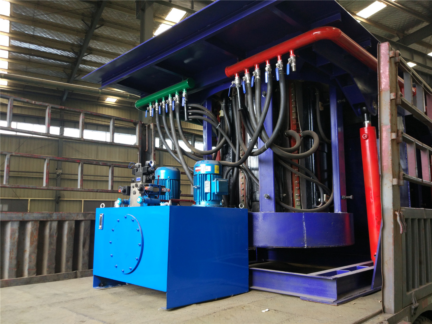
Protection and debugging method for induction melting furnace system
1 Limited voltage debugging
1) Turn on the power, start the inverter, slowly increase the power potentiometer to gradually increase the intermediate frequency voltage. When the voltage reaches 750V, adjust the piezoelectric positioner W9 clockwise so that the intermediate frequency voltage does not rise with the rotation of the power potentiometer.
2) IF may occur when the IF voltage rises below 750V. There are three reasons: 1. The current limit action is early, first adjust the current limiter W5 slightly counterclockwise to see if the intermediate frequency voltage has risen. If it cannot rise, stop the transfer. 2. Pressure limit advance action. The piezoelectric positioner W9 can be adjusted counterclockwise to see if the voltage has risen. If there is any sign of rising, it can continue to adjust until it reaches 750V. 3. It may be caused by the inverter angle being too small. It should be tuned into a signal potentiometer, so that the ratio of the intermediate frequency voltage to the DC voltage is 1.5 times. At this point, the piezoelectric positioner is adjusted until the pressure limit is reached.
2. Overvoltage debugging
1) Start the power supply, slowly increase the power potentiometer to make the intermediate frequency voltage reach 750V, adjust the overvoltage protection potentiometer W8 clockwise to make the overvoltage protection action, and the overvoltage indicator light.
2) The power potentiometer returns to zero, so that the protection system is automatically reset. (The reset principle has been detailed in the previous chapter.) Turn the piezo W8 counterclockwise two to three times and release the limiter.
3) Restart the power supply so that the intermediate frequency voltage rises to 800v~820v, and slowly adjust the voltage bitperer W8 clockwise to make the overvoltage protection action and the overvoltage indicator light. Start again to verify that the overvoltage protection value is accurate.
4) Restore the limit voltage setting value and adjust the inverter angle potentiometer to make the ratio of the intermediate frequency voltage and the DC voltage about 1.4.
Note: The overvoltage limit voltage should be debugged under no-load conditions. These two adjustments are strictly prohibited under heavy load! Otherwise the consequences are serious!
3 Current limit debugging
1) Start the power supply once at no load, verify the basic starting performance of the power supply and whether the instruments are normal.
2) Fill the furnace with the charge, preferably a larger block, in order to change the amount of charge. (The furnace is full of materials; common furnace)
3) Restart the power supply slowly and see if the starting performance of the heavy furnace is good. If the intermediate frequency voltage is difficult to establish at startup, it is difficult to start. The iC signal of the potentiometer should be adjusted to increase the angle of the inverter.
4) Start slowly again. After the startup is successful, gradually increase the power (at this time, the current is slower). When the current reaches the rated value, the current limiter W5 is adjusted so that the current does not rise with the power potentiometer.
There may be several situations in this debugging;
1 When the overcurrent is not reached, the action is first protected. At this time, the overcurrent protection action value can be amplified by counterclockwise adjustment of the flow potentiometer W7.
2 When the power potentiometer is turned to the maximum position, the current does not reach the rated value. The gap of the charge is large, which is not caused by the fact that a small piece of material is added in the gap of the large material to make the charge actually.
3 The inverter angle is small and the current is not going up. (This point has been described in detail in the section of the inverter working principle.) Just adjust the ic signal potentiometer to increase the inverter angle.
4 Overcurrent debugging
1) Slowly start the power supply, the current reaches the rated value, and the over-current protection device W8 is adjusted to make the over-current protection action.
2) Release the current limiting potentiometer W5 and turn the overcurrent potentiometer W7 counterclockwise two to three times.
3) Start the power supply is 1.2 times the rated current, adjust the over-current potentiometer W7 to make the over-current protection action, and the over-current indicator light. This debugging is repeated one or two times, and it is verified that the overcurrent value is indeed about 1.2 times of the rated current.
4) Restore the current limit setting value, adjust the current negative feedback potentiometer W6: firstly select the current negative feedback potentiometer counterclockwise to select the end, start the inverter to make the current at 100A, then adjust the negative feedback potentiometer clockwise to reduce the current to 75A. . End of the test.
Note: From the process of debugging, it can be seen that the voltage limiting current limit is debugged first, and then the overvoltage and overcurrent are debugged. Why not debug overvoltage and overcurrent first? This is the debugging step used for security reasons. Because the equipment is installed on site, the first on-site commissioning, it is inevitable that there will be such a bad factor, and accidentally will cause a big mistake. The consequences are unimaginable. Assume that the overvoltage or overcurrent is first debugged, and when the voltage or current rises to the rated value, once the insulation of the furnace is not good, it is easy to cause breakdown and sparking between the induction coil and the furnace shell, forming a short circuit to the ground, or forming a short circuit. Short circuit, the current is likely to be many times the rated value. The use of artificial to stop, it is not up to the speed of equipment protection, the consequences are very serious. Only the protection of the device itself can avoid undue losses. This is the reason for first adjusting the pressure limiting current limit and then adjusting the overpressure and overcurrent.
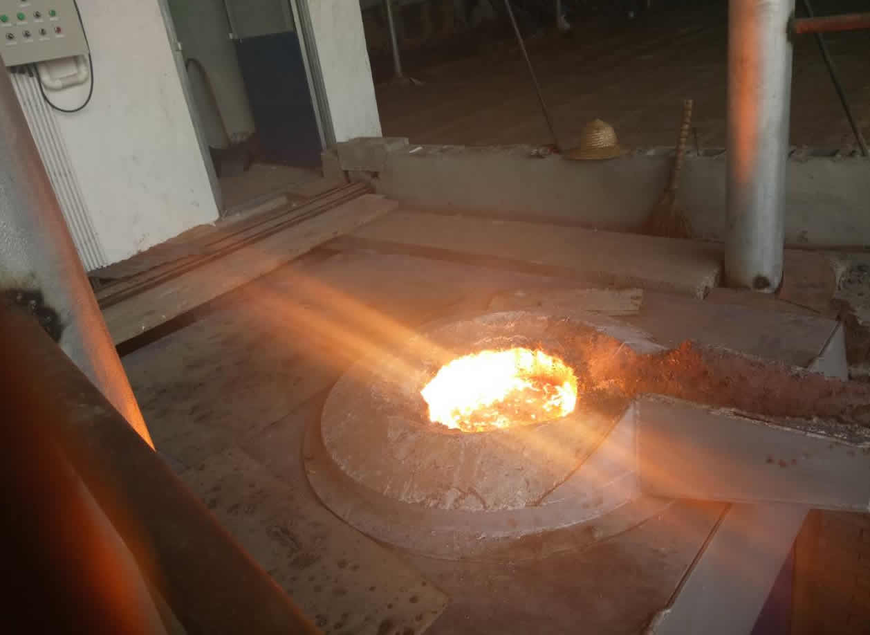
Iron induction furnace
Aluminum melting furnace
Copper melting furnace
Small steel melting furnace
Small induction melting furnace
Induction iron furnace
3T intermediate frequency iron melting f

0.25T Intermediate Frequency Furnace

0.5T Intermediate Frequency Furnace

Medium Frequency Furnace

2T Induction Melting Furnace

1T Induction Melting Furnace

500kg Induction Melting Furnace

250kg Induction Melting Furnace

Induction Melting Furnace

3 T Induction Melting Furnace

5T Induction Melting Furnace
1T One Belt Two Intermediate Frequency F

5T One Belt Two Intermediate Frequency F
3T One Belt Two Intermediate Frequency F
2T One Belt Two Intermediate Frequency F
5T Parallel Intermediate Frequency Furna

5T Intermediate Frequency Furnace

5T Series Intermediate Frequency Furnace
3T Series Intermediate Frequency Furnace
2T Series Intermediate Frequency Furnace
1T Series Intermediate Frequency Furnace
0.5T Series Intermediate Frequency Furna

0.25T Series Intermediate Frequency Furn
1T Parallel Intermediate Frequency Furna
2T Parallel Intermediate Frequency Furna
0.5T Parallel Intermediate Frequency Fur
Product Class