Sales hot line ( 24 hours service): 18037961302
E-Mail: firstfurnace@gmail.com
whatsapp:+8618037961302
Adress: Luoxin Industrial Park, Luoyang, HenanLarge diameter steel pipe quen
Piston rod quenching and tempe
Grinding rod quenching and tem
High frequency induction heate
Quenching equipment for machin
Round steel end heating furnac
Steel pipe heat treatment prod
Square steel quenching and tem
Sucker rod quenching and tempe
Thickened petroleum steel pipe
Round steel quenching and temp
Steel pipe quenching and tempe
Steel plate quenching and temp
Induction Hardening Machine&nb
Flywheel ring gear high freque
An induction melting furnace for efficiently melting gold
Technical field
[0001] The utility model relates to the field of gold smelting, in particular to an induction melting furnace.
Background technique
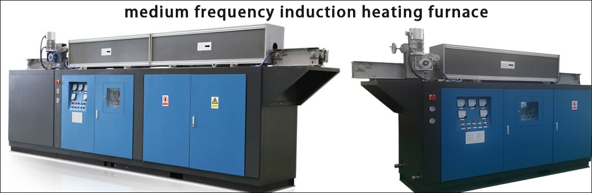
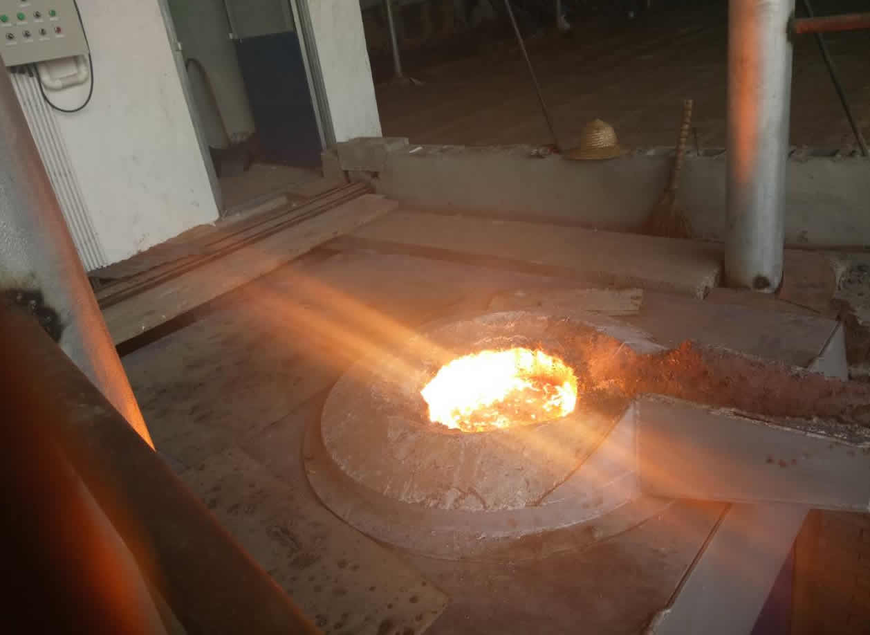
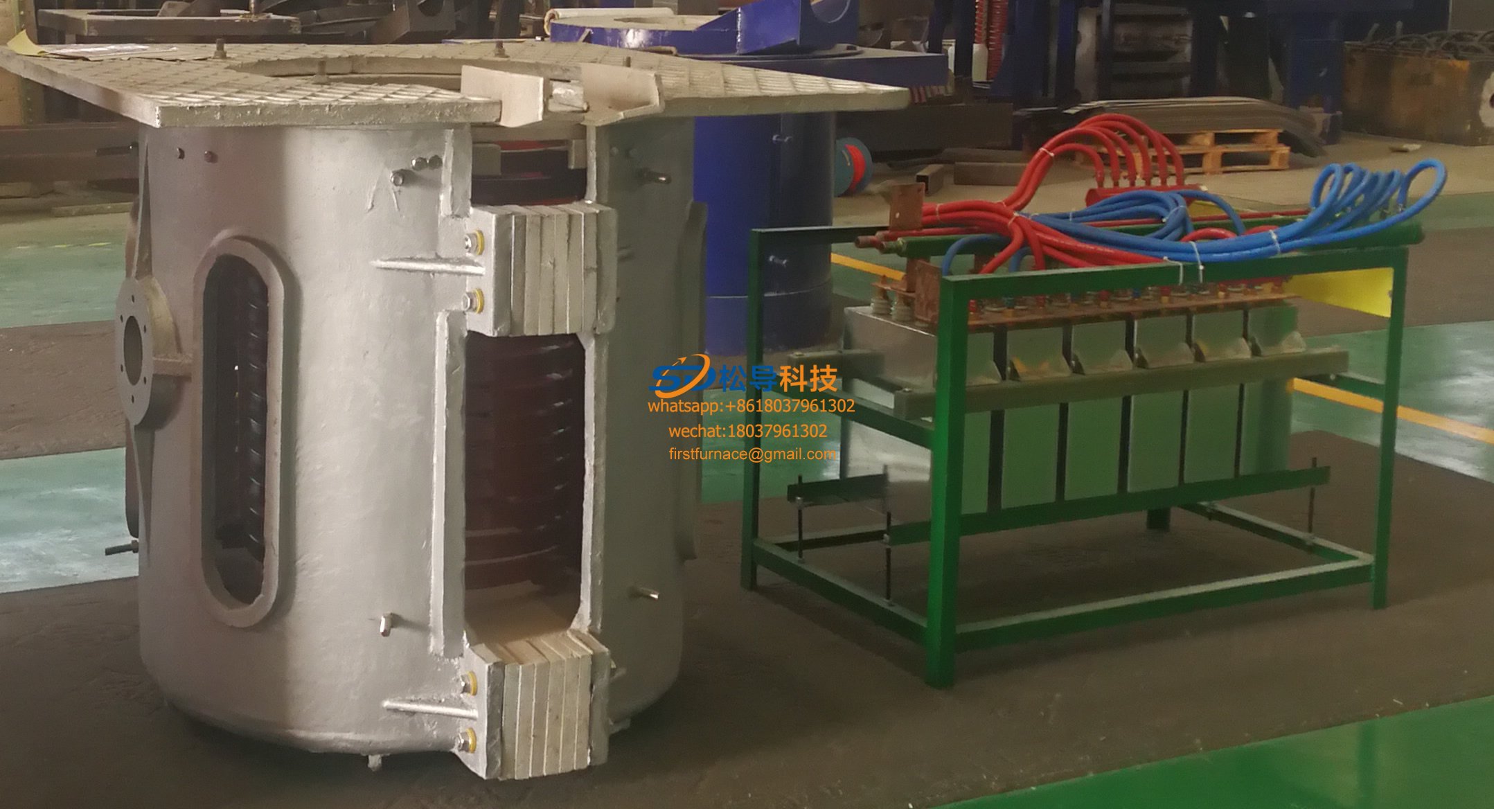
[0002] The induction melting furnace is a power supply device that converts 50HZ power frequency alternating current into intermediate frequency current. It converts three-phase power frequency alternating current into direct current after rectification, and then converts the direct current into an adjustable intermediate frequency current, which is supplied to the induction coil. Thereby, high-density magnetic lines of force are generated in the induction coil generated by the induction coil, and the metal material contained in the induction coil is cut, in the metal material
A large eddy current is generated. Use the principle of electromagnetic induction to heat metal. Compared with other casting equipment, induction melting furnace has the advantages of high thermal efficiency, short melting time, less alloy element burning loss, wide melting material, low environmental pollution, and accurate control of the temperature and composition of molten metal.
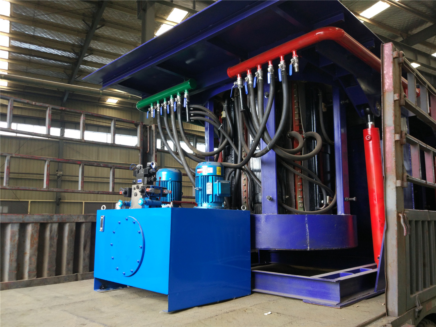
[0003] The existing induction melting furnace adopts a method in which the entire furnace body is tilted together when pouring and discharging. This requires the installation of cylinders, hydraulic cylinders and other equipment that can support the furnace body on the side of the furnace body. The piston rods and cylinder blocks of these equipment are usually made of gold.
It’s made of genus, which will inevitably be affected by the induction coil when it is close to the induction coil, so that the service life of the device
Greatly reduced.
Summary of the invention
[0004] The purpose of the present utility model is to provide a convenient and efficient medium frequency induction furnace for melting gold.
[0005] In order to achieve the above-mentioned purpose of the invention, the technical solution adopted by the present utility model is: a high-efficiency MF sensor for melting gold
The furnace includes a base body, a support and a crucible are arranged on the base body, a panel is arranged on the top of the support, and the bottom of the panel is arranged
The shielding plate, the panel and the middle of the shielding plate are provided with a through hole matching the crucible; the crucible is placed on the base through the through hole, and the crucible
An induction coil is arranged on the outside of the crucible, and the induction coil is fixed to the base; the upper part of the side of the crucible is centered on the axis of the crucible
Two bearings are arranged symmetrically; also including a clamping assembly, which includes a ceiling fixedly arranged above the crucible
The first piston cylinder facing downwards, the output end of the first piston cylinder is connected to the mounting seat, and a set of the mounting seat is opposite
A second piston cylinder extending laterally is respectively provided on the side surface, the output end of the second piston cylinder and one end of the first connecting rod
Connected, the other end of the first connecting rod is provided with a connecting shaft, the first connecting rod and the connecting shaft form an angle of 900, and the connecting shaft passes
The bearing is connected to the crucible.
[0006] Preferably, the bottom of the mounting seat is provided with a downwardly facing third piston cylinder, and the output end of the third piston cylinder is divided into
Do not hinge with one end of the two second links, and the other end of the second link is hinged with the middle of the first link; the second
The output end of the piston cylinder is hinged with the first connecting rod.
[0007] Preferably, the upper part of the side of the crucible is provided with a pouring trough, and the connecting line between the pouring trough and the axis of the crucible is perpendicular
At the connecting line of the two bearings, a connecting ring is provided on the side of the upper part of the crucible opposite to the pouring trough, and the connecting ring passes through the hanging
The hook is connected with the chain, the chain is wound on the reel, and the reel is driven by a decelerating motor, and the decelerating motor is connected to the control
The reel and the geared motor are fixed to the mounting base,
[0008] Preferably, a fan is provided on the panel, the air inlet of the fan faces the opening of the crucible, and the air outlet of the fan
Connect with the sewage pipe.
[0009] The beneficial effects of the present utility model are concentrated in that it can greatly increase the service life of the equipment and is convenient to use.
Specifically, the present invention abandons the traditional induction melting furnace that lifts the furnace body from one side of the furnace body for dumping, but instead
The clamping component and the bearing fixed on the crucible are used for dumping, so that the flexibility is higher and can be realized.
Movement of the crucible. At the same time, because the clamping assembly can be moved away from the induction coil after being lifted by the first piston cylinder, it is affected by
The influence to the induction coil is small, supplemented by the setting of the shielding plate, thereby greatly improving the service life of the utility model.
Description of the drawings
[0010] FIG. 1 is a schematic diagram of the structure of the utility model;
[0011] FIG. 2 is an A-A view of the structure shown in FIG. 1;
[0012] FIG. 3 is a schematic diagram of a use state of the structure shown in FIG. 2;
[0013] FIG. 4 is a schematic diagram of another use state of the structure shown in FIG. 2.
DETAILED DESCRIPTION [0014] Combining an intermediate frequency induction furnace for high-efficiency gold melting as shown in FIGS. 1-4, it includes a base body 1, on which a bracket 2 and a crucible 3 are arranged, and a panel 4 is arranged on the top of the bracket 2 A shielding plate 5 is provided at the bottom of the panel 4, and the shielding plate 5 can be fixed to the panel 4 by bolts, of course, it can also be fixed by other ways that have the same effect. The middle part of the panel 4 and the shielding plate 5 is provided with a through hole matched with the crucible 3, that is to say, the size of the through hole matches the caliber of the crucible 3. The crucible 3 is placed on the base 1 through the through hole, an induction coil 6 is arranged outside the crucible 3, and the induction coil 6 is fixed to the base 1. As shown in FIG. 2, two bearings 7 are symmetrically arranged on the upper part of the crucible 3 with the axis of the crucible 3 as the center. The present invention also includes a clamping assembly, which includes a downwardly facing first piston cylinder 8 fixedly arranged on the ceiling above the crucible 3, and the output end of the first piston cylinder 8 is connected with the mounting seat 9, and The mounting seat 9 is usually in the shape of a rectangular parallelepiped or a cube. A set of opposite sides of the mounting seat 9 are respectively provided with a second piston cylinder 10 extending laterally. The output end of the second piston cylinder 10 is connected to the first connecting rod. One end of the first connecting rod 11 is connected, and the other end of the first connecting rod 11 is provided with a connecting shaft 12. The first connecting rod 11 forms an angle of 900 with the connecting shaft 12, and the connecting shaft 12 is connected to the crucible 3 through a bearing 7. [0015] During the use of the utility model, the standby process is shown in Figure 4, at this time the gold is directly poured into the crucible 3, and then the power is turned on. Since the clamping assembly can be lifted under the drive of the first piston cylinder 8 and far away from the induction coil 6, the service life of the utility model is greatly improved. After the gold is smelted to a molten state, turn off the power. Start the second piston cylinder 10, the piston rod extends so that the connecting shaft 12 on the first connecting rod 11 reaches the position opposite to the bearing 7, that is to ensure that the connecting shaft 12 does not interfere with the bearing 7 and the crucible 3 during the downward movement. . Then the first piston cylinder 8 is activated, the piston rod extends to drive the entire clamping assembly to move down to a position where the connecting shaft 12 is parallel to the inner hole of the bearing 7, and then the second piston cylinder 10 is controlled to retract. The connecting shaft 12 is inserted into the bearing 7. In order to further improve the connection strength between the connecting shaft 12 and the bearing 7, a downwardly facing third piston cylinder 13 is provided at the bottom of the mounting seat 9, and the output end of the third piston cylinder 13 is connected to the two second connecting rods 14 respectively. One end is hinged, and the other end of the second link 14 is hinged with the middle of the first link 11. The output end of the second piston cylinder 10 is hinged with the first connecting rod 11. In this way, the crucible 3 can be further locked by the action of the third piston cylinder 13.
[0016] Next, the first piston cylinder 8 is controlled to retract to realize the lifting of the crucible 3 as shown in FIG. 3. Because the crucible 3 is separated from the base 1, the support 2, the panel 4, the induction coil 6, and other components, Therefore, whether it is moving the crucible 3 or directly using the crucible 3 for pouring, its flexibility is far greater than that of a conventional induction melting furnace. The staff can tilt the crucible 3 by holding the tongs so that
The gold solution in the crucible 3 is poured out for pouring, in order to improve the performance of the utility model. A pouring trough 16 can also be provided on the upper part of the side of the crucible 3, and the connecting line between the pouring trough 16 and the axis of the crucible 3 is perpendicular to the connecting line of the two bearings 7, and the upper part of the crucible 3 is connected to the pouring trough 16 A connecting ring 17 is provided on the opposite side. The connecting ring 17 is connected to a chain 19 through a hook 18, and the chain 19 is wound on a reel 20, which is driven by a reduction motor 21, which is connected to The controller is connected, and the reel 20 and the reduction motor 21 are fixed to the mounting base 9. After the hook 18 is hooked on the connecting ring 17, the crucible 3 can be dumped by rolling up the chain 19 by the reel 20. Of course, the controller can also be connected with the first piston cylinder 8, the second piston cylinder 10, and the third piston cylinder 13 to improve the level of intelligence. Furthermore, a fan 15 can also be provided on the panel 4, the air inlet of the fan 15 faces the opening of the crucible 3, and the air outlet of the fan 15 is connected to the sewage pipe 30. The fan 15 can suck harmful gas or dust generated by smelting into the sewage pipe 30 to purify the production environment.


Iron induction furnace
Aluminum melting furnace
Copper melting furnace
Small steel melting furnace
Small induction melting furnace
Induction iron furnace
3T intermediate frequency iron melting f

0.25T Intermediate Frequency Furnace

0.5T Intermediate Frequency Furnace

Medium Frequency Furnace

2T Induction Melting Furnace

1T Induction Melting Furnace

500kg Induction Melting Furnace

250kg Induction Melting Furnace

Induction Melting Furnace

3 T Induction Melting Furnace

5T Induction Melting Furnace
1T One Belt Two Intermediate Frequency F

5T One Belt Two Intermediate Frequency F
3T One Belt Two Intermediate Frequency F
2T One Belt Two Intermediate Frequency F
5T Parallel Intermediate Frequency Furna

5T Intermediate Frequency Furnace

5T Series Intermediate Frequency Furnace
3T Series Intermediate Frequency Furnace
2T Series Intermediate Frequency Furnace
1T Series Intermediate Frequency Furnace
0.5T Series Intermediate Frequency Furna

0.25T Series Intermediate Frequency Furn
1T Parallel Intermediate Frequency Furna
2T Parallel Intermediate Frequency Furna
0.5T Parallel Intermediate Frequency Fur