Sales hot line ( 24 hours service): 18037961302
E-Mail: firstfurnace@gmail.com
whatsapp:+8618037961302
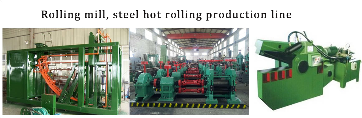
Adress: Luoxin Industrial Park, Luoyang, HenanLarge diameter steel pipe quen
Piston rod quenching and tempe
Grinding rod quenching and tem
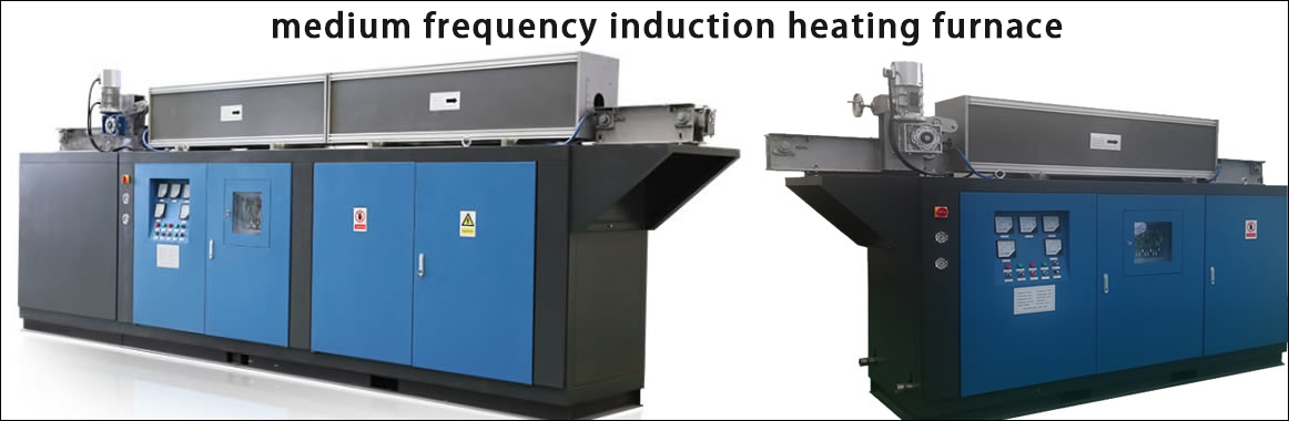
High frequency induction heate
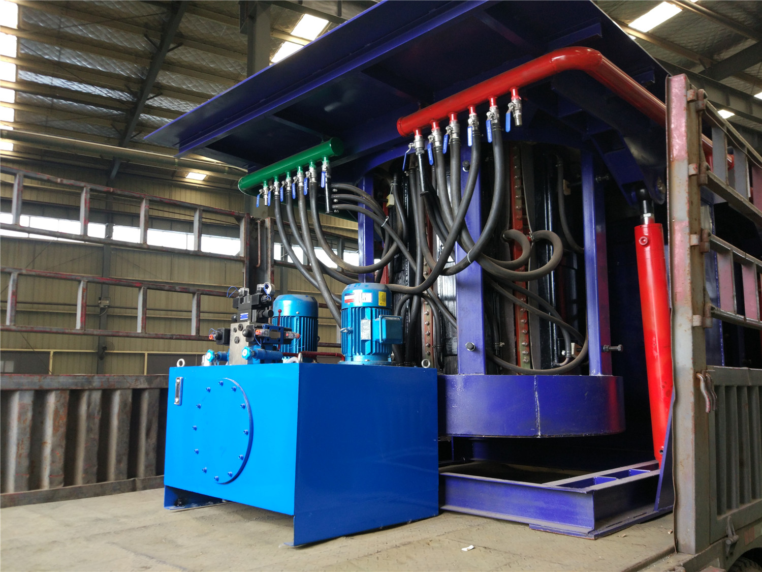
Quenching equipment for machin
Round steel end heating furnac
Steel pipe heat treatment prod
Square steel quenching and tem
Sucker rod quenching and tempe
Thickened petroleum steel pipe
Round steel quenching and temp
Steel pipe quenching and tempe
Steel plate quenching and temp
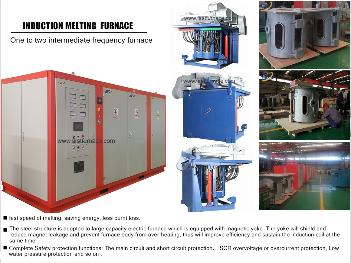
Induction Hardening Machine&nb
Flywheel ring gear high freque
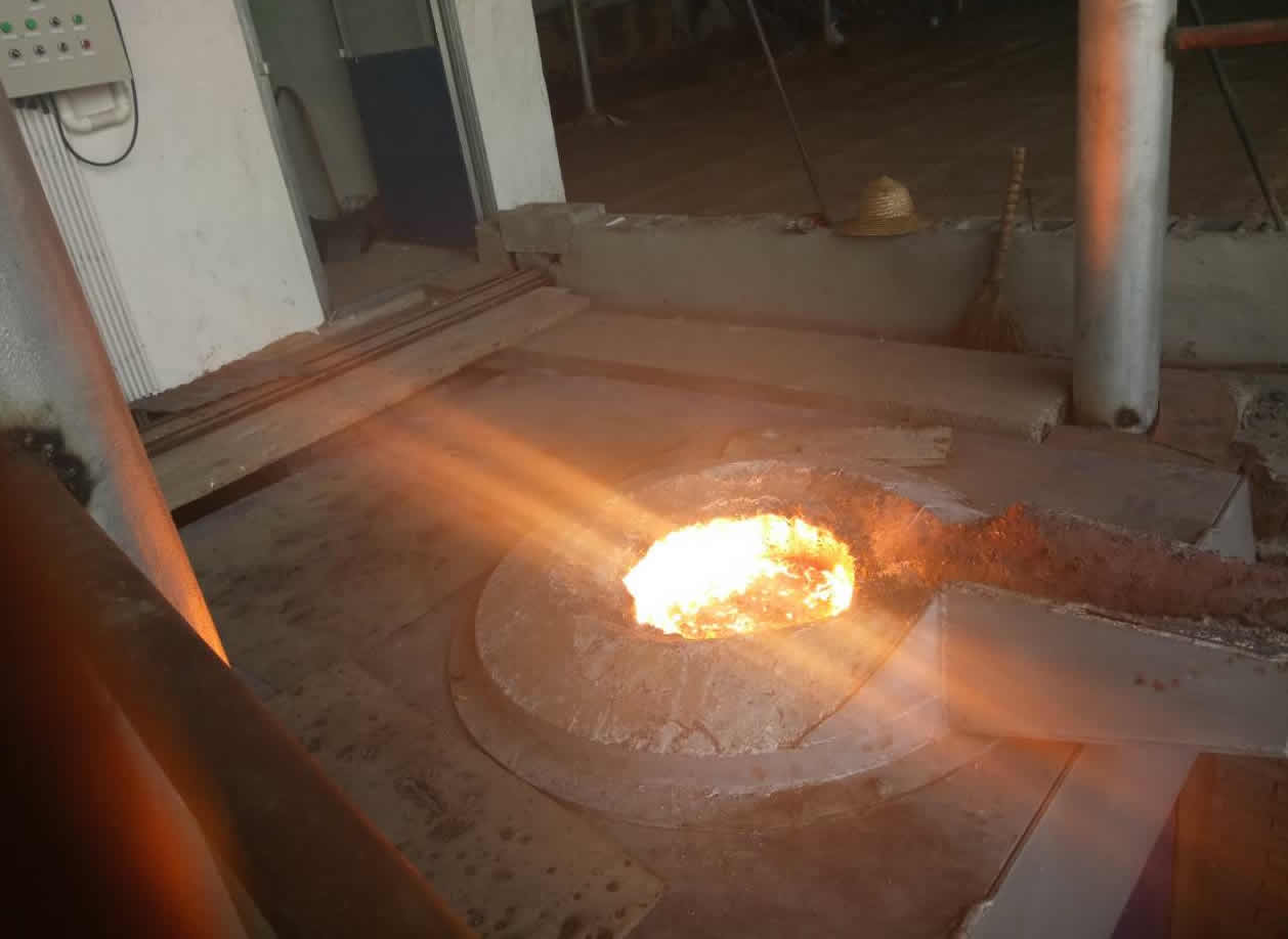
Interpretation of Power Factor of Induction Melting Furnace
The most basic explanation of the power factor of an induction melting furnace: an example of an induction melting furnace: the power of an induction melting furnace is 100 units, that is, 100 units of power are delivered to the induction melting furnace. However, due to the inherent reactive power loss of most electrical systems, only 70 units of power can be used. Unfortunately, although only 70 units are used, 100 units have to be paid. In this example, the power factor is 0.7 (if the power factor of most induction melting furnaces is less than 0.9, it will be fined). This reactive power loss mainly exists in the motor induction melting furnace (such as blowers, pumps, compressors, etc.) ), also called inductive load. Power factor is a measure of motor performance.
The basic explanation of the power factor of the induction melting furnace: each motor system consumes two large powers, which are the real useful work (called kilowatts) and the reactive useless work. Power factor is the ratio between useful work and total power. The higher the power factor, the higher the ratio of useful work to total power, and the more efficient system operation.
Advanced explanation of power factor of induction melting furnace: In an inductive load circuit, the peak value of the current waveform occurs after the peak value of the voltage waveform. The separation of the peaks of the two waveforms can be expressed by the power factor. The lower the power factor, the greater the separation between the two waveform peaks. Paulkin can bring the two peaks closer together again, thereby improving the efficiency of the system.
The power factor is one of the important technical data of AC circuits. The level of power factor is of great significance to the utilization and analysis of electric induction melting furnaces, as well as the study of electric energy consumption and other issues. The so-called power factor refers to the cosine of the phase difference between the voltage U at both ends of any two-terminal network (a circuit with two contacts with the outside world) and the current I in it. The power consumed in the two-terminal network refers to the average power, also called active power, which is equal to: P=UIcosΦ. From this, it can be seen that the power P consumed in the circuit depends not only on the voltage V and the current I, but It is also related to power factor. The power factor depends on the nature of the load in the circuit. For resistive loads, the phase difference between voltage and current is 0, so the power factor of the circuit is the largest (); while for pure inductive circuits, the phase difference between voltage and current is π/2, and the voltage leads the current; in pure capacitance In the circuit, the phase difference between the voltage and the current is-(π/2), that is, the current leads the voltage. In the latter two circuits, the power factor is zero. For general load circuits, the power factor is between 0 and 1.
Generally speaking, in a two-terminal network, improving the power factor of electrical appliances has two meanings. One is to reduce power loss on transmission lines; the other is to make full use of electric induction melting furnaces (such as generators, transformers, etc.). )potential. Because electrical appliances always work under the conditions of a certain voltage U and a certain active power P, the formula I=P/UcosΦ
It can be seen that if the power factor is too low, it is necessary to use a larger current to ensure the normal operation of electrical appliances. At the same time, the transmission current on the transmission line increases, which leads to an increase in Joule heat loss on the line. The voltage drop on the resistance of the transmission line and the inner group of the power supply is proportional to the current in the consumer. Increasing the current will inevitably increase the voltage loss in the transmission line and the power supply. Therefore, improving the power factor of electrical appliances can reduce the transmission current, thereby reducing the power loss on the transmission line.
It is not difficult to understand that by improving the power factor, the potential of the electric induction melting furnace can be fully utilized. Because any electric induction melting furnace is always working within a certain rated voltage and rated current limit. The working voltage exceeding the rated value will threaten the insulation performance of the induction melting furnace; the working current exceeding the rated value will cause the internal temperature of the induction melting furnace to rise too high, thereby reducing the service life of the induction melting furnace. For the electric induction melting furnace, the product of the voltage and the current rating is called the rated apparent power of the induction melting furnace S, that is, S = U and I, and it is also called the capacity of the induction melting furnace. For generators In other words, this capacity is the maximum power that the generator may output. It indicates the power generation potential of the generator. As for the actual output power of the generator, it is related to the power factor of the electrical appliance. The power consumed by the electrical appliance is P=S rating. cosΦ
A high power factor means that the active power accounts for a large proportion of the rated apparent power, and the electrical energy output by the generator is fully utilized. For example, if the capacity of the generator is 15,000 kVA, when the power factor of the power system is increased from 0.6 to 0.8, the actual power generation capacity of the generator can be increased by 3000 kW. This is not exactly the effect of the generator. Potential? The utilization of induction melting furnace is also more reasonable. From this perspective, power factor can be expressed as the ratio of active power to machine power, that is, cosΦ=P/S
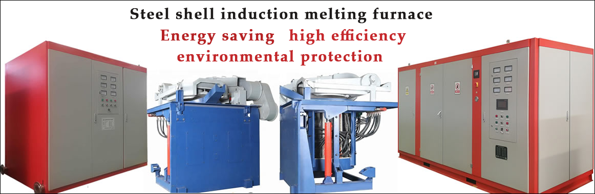
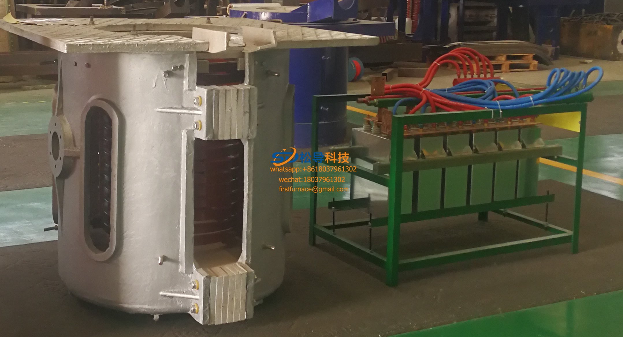
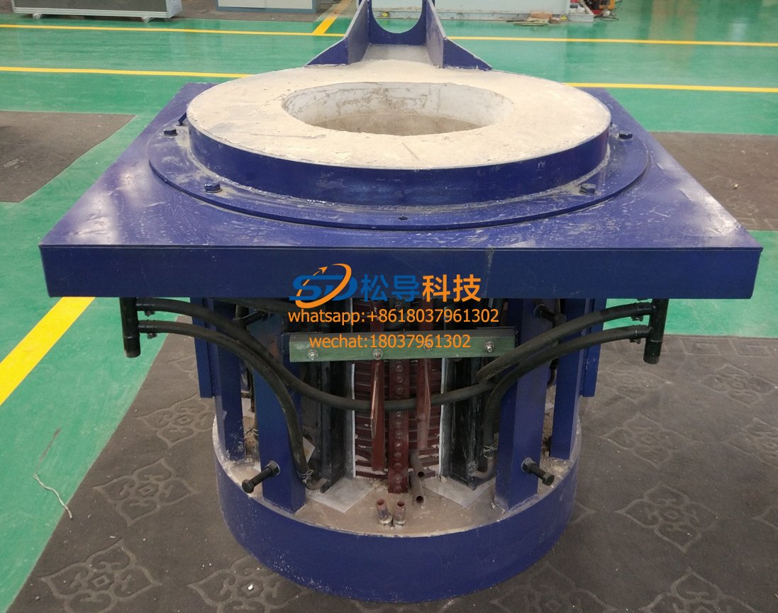
Iron induction furnace
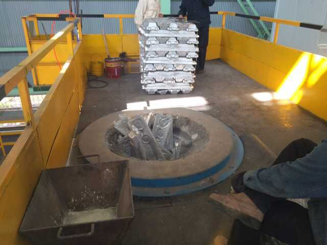
Aluminum melting furnace
Copper melting furnace
Small steel melting furnace
Small induction melting furnace
Induction iron furnace
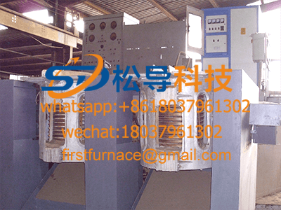
3T intermediate frequency iron melting f

0.25T Intermediate Frequency Furnace

0.5T Intermediate Frequency Furnace

Medium Frequency Furnace

2T Induction Melting Furnace

1T Induction Melting Furnace

500kg Induction Melting Furnace

250kg Induction Melting Furnace

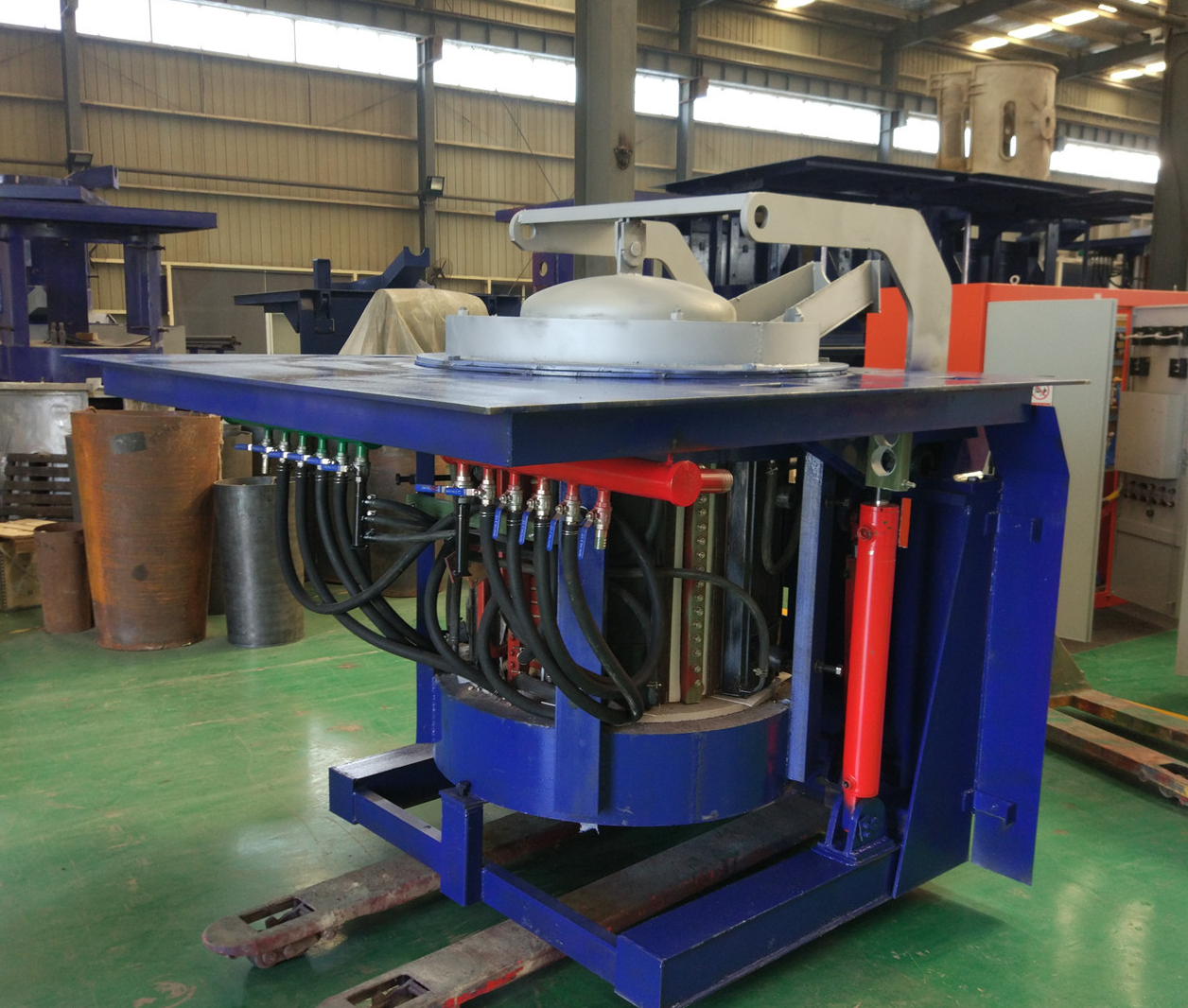
Induction Melting Furnace

3 T Induction Melting Furnace

5T Induction Melting Furnace
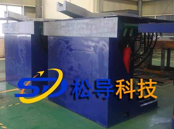
1T One Belt Two Intermediate Frequency F

5T One Belt Two Intermediate Frequency F
3T One Belt Two Intermediate Frequency F
2T One Belt Two Intermediate Frequency F
5T Parallel Intermediate Frequency Furna

5T Intermediate Frequency Furnace

5T Series Intermediate Frequency Furnace
3T Series Intermediate Frequency Furnace
2T Series Intermediate Frequency Furnace
1T Series Intermediate Frequency Furnace
0.5T Series Intermediate Frequency Furna

0.25T Series Intermediate Frequency Furn
1T Parallel Intermediate Frequency Furna
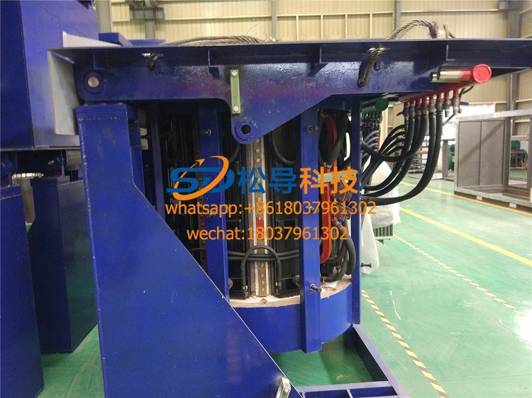
2T Parallel Intermediate Frequency Furna
0.5T Parallel Intermediate Frequency Fur